Hybrid Reconfigurable Intelligent Surface Enabled Over-the-Air Index-Modulation
Abstract
Users’ desire for enhanced performance drive the inevitable technological progress on vertical applications in wireless communication systems. To meet these demands, researchers vigorously investigate potential 6G and beyond technologies and solutions. Reconfigurable intelligent surfaces (RISs) have risen in popularity and attracted the attention of academia as well as industry and seem to be a promising candidate for 6G technology. RISs are reflective metamaterials with many configurable elements consisting of pin diodes that have the ability to manipulate the impinging signals’ properties, hence, enabling some sort or virtual control over the wireless channel. In this paper, we propose a novel over-the-air index modulation (IM) scheme through the use of a hybrid RIS with active and passive partitions to convey additional IM bits over-the-air. In addition we propose another modified scheme that allows the transmission for even more IM bits but at the expense of certain trade-offs. First, we present the system model for both of the proposed schemes. Furthermore, comprehensive computer simulation results are provided and discussed presenting the superior bit error rate (BER) performance and additional benefits of the proposed systems compared to similar benchmarks.
Index Terms:
reconfigurable intelligent surface (RIS), hybrid RIS, index modulation, partitioning, 6G, BER, spectral efficiency, data rateI Introduction

Wireless communication technologies are rapidly developing as researchers migrate from one generation (5G) to another (6G), striving to meet users’ stringent demands as a consequence of imminent vertical applications. Numerous candidate solutions and novel technologies are proposed in the literature each manifesting high potential for future wireless communication systems. While some methods are adopted, most of these are dismissed and are not favored due to distinct drawbacks and critical issues which may be in terms of practicality, performance, complexity and more. However, as new hot topics arise, researchers must revert to previous solutions and consider them and their integration with recently developed and considered technologies which may provide new insights and together provide superior performance. Hence, previously dismissed technologies may be rekindled as once again significantly promising solutions.
Index modulation (IM) is a simple, spectrum and energy efficient scheme to embed and transmit additional information bits through the indices of resource blocks in communication systems [1, 2, 3, 4]. These resource blocks on which information is embedded can be subcarriers, antennas, time-slots, constellation, activation orders and much more [5, 3]. It is a very popular concept with a significant amount of research and studies conducted on it and has proven itself to be a worthy tool and is considered for future communication networks. IM shows benefits such as the ability to improve error performance, provide enhanced energy and spectral efficiency, and all while providing low complexity [6]. One of the most important characteristic of IM is its flexibility and compatibility attribute since it can be employed and coexist in a wireless communication system in numerous methods [5, 7]. One example is orthogonal frequency division multiplexing-IM (OFDM-IM) where IM is incorporated in the subcarriers of an OFDM waveform as an addition layer of modulation by activating certain subcarriers to transmit additional bits over OFDM subblock [8, 9]. In [10] and [11], IM has been integrated with non-orthogonal multiple access and joint radar and communication technologies introducing novel system designs for future technologies; proposing a flexible OFDM-IM subcarrier activation and power allocation method according to users’ needs and a unique waveform to serve both communication and radar functionalities, respectively. Furthermore, additional interesting studies have been conducted such as [12] where a novel technique is proposed by dividing the subcarriers into two groups and modulating them with distinguishable mode constellations and [13] where bits are transmitted through the indexing of multiple codebooks to be used in sparse vector coding for ultra-reliable low-latency communication networks.
Reconfigurable intelligent surfaces (RISs) have recently risen in popularity in the wireless communication community and exhibit high potential as a promising candidate for future 6G and beyond wireless communication systems. RISs are large reflective surfaces with numerous small and low-cost meta-material elements that have the ability to manipulate the characteristics of impinging signals. Hence, RISs are able to reflect, refract, absorb and even amplify impinging signals without the need for additional buffering or processing, providing some sort of virtual control over the wireless channel. Generally, RISs are envisioned to be employed for coverage enhancement, increased signal quality, elevated capacity and other system performance improvements [14, 15, 16, 17, 18, 19]. One significant advantage of the RIS technology is its flexibility in the integration with conventional technologies. There are many studies that present substantial benefits in the integration of RIS with previously considered technologies such as non-orthogonal multiple accessing [20], machine learning [21], localization [22], OFDM [23], mutiple-input and multiple-output [24], and much more [25, 26, 27].
Considering both the advantages and flexibility of RIS and IM, the integration of these technologies are being investigated to further improve wireless communication system performances. In [28], the authors present a greedy detector for an RIS space-shift keying system where the RIS phases are aligned to maximize the instantaneous signal-to-noise ratio (SNR) at the target receive antenna which is selected through IM bits. Furthermore, an intelligent RIS grouping-based IM (RGB-IM) is proposed to enhance the spectral efficiency and bit error rate (BER) performance of conventional RIS systems [29]. In this study the RIS is divided in to multiple groups each with the same number of elements, and according to the incoming IM bits a group of RIS elements are activated while the other RIS elements are inactive and introduce zero phase. However, completely inactivating remaining groups and elements are not optimal and could be used in a more efficient manner to improve the reliability and spectral efficiency of the system.
In this study, we propose a novel over-the-air RIS-IM (OTA-RIS-IM) technique exploiting the entire RIS enhancing the spectral efficiency and BER performance. We present a hybrid RIS that has multiple groups and each group can be active and passive according to the IM bits. Furthermore, we further expand this system design and propose an enhanced OTA-RIS-IM (E-OTA-RIS-IM) system by introducing an absorption mode at the RIS to send additional IM bits at the expense of slightly reduced BER performance improvement compared to our benchmark.
The rest of the paper can be summarized as follows. In Section II, the system framework of the proposed OTA-RIS-IM and E-OTA-RIS-IM scheme is presented. In addition, Section III consists of the computer simulation results and discussions while Section IV concludes the paper.
II System Model
In this section, we provide the system model for both of the proposed schemes. First we will present the initial OTA-RIS-IM system design. Furthermore, we will build on top of it to propose the E-OTA-RIS-IM system. As seen from Fig. 1, RIS includes elements and is partitioned into groups, each including elements, . Here, the reflection coefficient of the th element of the th RIS group is with unit amplitude, where is the phase shift adjusted by the RIS controller, , and .
Assume that and represent the large scale path loss of the BS-to-RIS and RIS-to-UE, respectively, where , is the path loss at the reference distance of 1 meter, and , and , denote the distance from BS to RIS and RIS to UE, the path loss exponents at BS to RIS and RIS to UE paths, respectively. Then, we define the channel coefficients from the BS to the th RIS element and from the th RIS element to the UE as and , respectively. Moreover, and are independent Rician fading channel coefficients as follows:
| (1) | ||||
| (2) |
where and represent the line-of-sight (LoS) components and and represent the non-LoS (NLoS) components of and , respectively, whereas and denote the Rician factor of the paths between the BS-RIS and the RIS-UE, respectively. Here, , , , and are independent and identically distributed complex Gaussian random variables with .
II-A OTA-RIS-IM
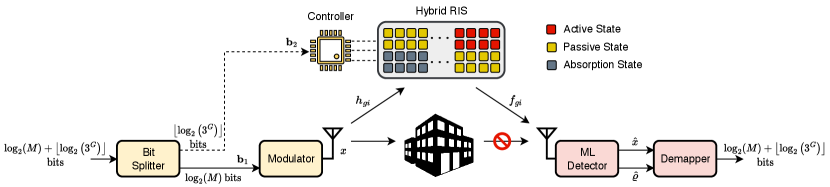
The system model of OTA-RIS-IM is demonstrated in Fig. 1. In OTA-RIS-IM, information bits are transmitted both through the conventional -ary PSK/QAM signal constellation and also the indices of the active/passive states of RIS groups. Firstly, bit vector is mapped into the modulated symbol , , where is the -ary PSK/QAM signal constellation and . Then, bit vector determines the indices of active/passive states of RIS groups , , . Here, the th element of is equal to the th element of , i.e., . If is equal to (), then the th RIS group is in passive state, and if is equal to (), then the th RIS group is in active state, where represents the logical NOT of . Here, the number of ones and zeros in is equal to the number of active () and passive () RIS groups, respectively, . In Table I, an example of bit mapping is given for . The spectral efficiency of OTA-RIS-IM in terms of bit per channel use (bpcu) can be given as:
| (3) |
In OTA-RIS-IM, the th RIS element () is selected in such a way that the phase terms in and are eliminated, i.e., . Hence, the received signal at UE can be given as:
| (4) | |||
where , , , and are the transmit power, amplification factor at the active RIS groups, additive white Gaussian noise (AWGN) sample with distribution , and amplifier noise term at the th RIS element with distribution , respectively. Finally, at the UE, the maximum-likelihood (ML) detection rule can be exploited to decode the received signal as follows:
| (5) |
where and are the estimates of and , respectively, and is a set including all possible vectors. Here, number of iterations are performed in the search space to decode the received signal.
The signal-to-noise ratio (SNR) of the received signal can be given as:
| (6) |
|
|
|||||||||||
|---|---|---|---|---|---|---|---|---|---|---|---|---|
| Passive | Passive | |||||||||||
| Passive | Active | |||||||||||
| Active | Passive | |||||||||||
| Active | Active |
II-B E-OTA-RIS-IM
In this subsection, we present an enhanced OTA-RIS-IM scheme (E-OTA-RIS-IM) to further improve the number of bits transmitted in the system by introducing an absorption state at the hybrid RIS. The system model of E-OTA-RIS-IM is illustrated in Fig. 2. Here, according to the incoming bits from the backhaul link, the hybrid RIS will determine whether the partitions will behave in the passive, active or absorption state. As in OTA-RIS-IM, firstly, bit vector is used to obtain the -ary modulated symbol , . Let us define a codebook which includes all permutations with repetition of active/passive/absorption states of RIS groups, , , where is the th codeword of set and , , . Here, being , , and represent active, passive, and absorption states, respectively. Hence, bit vector is converted into its decimal value (), and th codeword () of is selected. As seen in Table II, an example of states of RIS groups selection is provided for . Here, a total number of permutations can be generated; however, only can be used to transmit information. As can be seen in the table, for the same number of RIS partitions , we can send an additional bit compared to the previous method. Hence, the spectral efficiency of E-OTA-RIS-IM in terms of bpcu can be given as:
| (7) |
As in OTA-RIS-IM, the th element of RIS is coherently aligned with the corresponding channel coefficients and , i.e., . Hence, the received signal at UE can be written as:
| (8) |
where is a function which provides output as if equals to , and otherwise.
In order to decode the received signal, the ML detector can be used as follows:
| (9) |
Moreover, the SNR of the received signal can be obtained as:
| (10) |
|
Codeword |
|
|
|||||||
| Active | Active | |||||||||
| Active | Passive | |||||||||
| Active | Absorption | |||||||||
| Passive | Active | |||||||||
| Passive | Passive | |||||||||
| Passive | Absorption | |||||||||
| Absorption | Active | |||||||||
| Absorption | Passive | |||||||||
| NaN | NaN | NaN | Absorption | Absorption |
III Simulation Results and Comparisons


In this section, we will discuss the simulation results of the proposed OTA-RIS-IM and E-OTA-RIS-IM schemes in terms of BER performance compared to the RGB-IM benchmark [29] which only activates one group of the RIS. For a different number of RIS groups , various , and other parameters, we show the superior performance of the proposed scheme over the RGB-IM. Unless otherwise indicated, the following system parameters are assumed in all simulations: the distances and meters, the path loss exponents and , the Rician shape parameters , the noise variances and the reference path loss value of dB. For the BER analyses, the noise power and are fixed to dBm and the transmit power is varied.
Fig. 3 presents the error performance for all schemes with , , and bpcu for varying . It is observed that E-OTA-RIS-IM requires the least modulation order of since it can transmit additional bits through IM and is the most spectral efficient. On the other hand, OTA-RIS-IM needs and RGB-IM benchmark operates at modulation orders to keep the same bpcu of . It is seen that both proposed schemes outperform the benchmark and OTA-RIS-IM provides the best performance of all schemes since it uses the entire RIS at all times due to not having absorption state as in E-OTA-RIS-IM and RGB-IM. Furthermore, the error performance of all schemes improves with respect to .
In Fig. 4, we can see the BER performance of the proposed schemes compared to the benchmark with for varying . To obtain same bpcu values in each scheme, the modulation order varies. It is observed that while E-OTA-RIS-IM needs only , OTA-RIS-IM needs to operate at modulation order. Despite a higher modulation order, OTA-RIS-IM outperforms E-OTA-RIS-IM in terms of error performance since it has all RIS elements on at all combinations. On the other hand, RGB-IM requires modulation order to keep up the same data rate. It is shown that the RGB-IM at the same bpcu performs significantly worse compared to both of the proposed schemes.
Fig. 5 presents the BER performance of the proposed systems compared to the benchmark when all of the systems are at the same bpcu and . As we can see, to reach the same bpcu RGB-IM requires a large amount of grouping to send additional bits through IM. On the other hand, OTA-RIS-IM needs only RIS groups to reach the same bpcu and E-OTA-IM needs even a fewer number since it has an additional state the hybrid RIS can take. It can also be observed that since there is no absorption state, even though the bpcu is less compared to E-OTA-RIS-IM, the BER performance is significantly superior because all RIS elements are exploited at all times.
Fig. 6 shows the increase in bpcu as the number of groups increases for each scheme. It can be observed, that as the number of groups increases the benchmark’s bpcu does not increase much since only one group is activated according to the IM bits each time and the rest of the RIS is inactive. On the other hand, OTA-RIS-IM uses the entire hybrid-RIS where each group may take an active and passive state according to IM bits and provides a significantly higher bpcu compared to the benchmark. Furthermore, E-OTA-RIS-IM introduces an absorption state at the RIS to further enhance the bpcu for a trade-off from reliability as we have seen from the previous BER figures. However, we can observe that the bpcu increases drastically for the E-OTA-RIS-IM scheme since the IM bits are increased to .
IV Conclusion
In this study, a novel OTA-RIS-IM and E-OTA-RIS-IM scheme has been proposed, exploiting the benefits of IM and RIS technology efficiently to enhance the spectral efficiency and BER performance of RIS-aided wireless communication systems. Through partitioning and varying the states of the groups at the hybrid-RIS, additional IM bits are conveyed over-the-air. Furthermore, extensive computer simulation results demonstrate and discuss the performance benefits of the proposed system. Future directions may include applications of machine learning, various methods to improve the transmission of IM bits, considering a multiple antenna system design, and other methods to further improve the performance and complexity of the proposed system design.
Acknowledgment
This study has been supported by the 1515 Frontier Research and Development Laboratories Support Program of TÜBİTAK under Project 5229901 - 6GEN. Lab: 6G and Artificial Intelligence Laboratory.
References
- [1] E. Basar, “Index modulation techniques for 5G wireless networks,” IEEE Commun. Mag., vol. 54, no. 7, pp. 168–175, Jul. 2016.
- [2] E. Basar, M. Wen, R. Mesleh, M. Di Renzo, Y. Xiao, and H. Haas, “Index modulation techniques for next-generation wireless networks,” IEEE Access, vol. 5, pp. 16 693–16 746, Aug. 2017.
- [3] M. Wen, X. Cheng, and L. Yang, Index modulation for 5G wireless communications. Springer, Jul. 2017, vol. 52.
- [4] O. F. Tugtekin, A. T. Dogukan, E. Arslan, and E. Basar, “Coordinate interleaved OFDM with repeated in-phase/quadrature index modulation,” IEEE Trans. Wirel. Commun., May 2023.
- [5] S. Sugiura, T. Ishihara, and M. Nakao, “State-of-the-art design of index modulation in the space, time, and frequency domains: Benefits and fundamental limitations,” IEEE Access, vol. 5, pp. 21 774–21 790, Oct. 2017.
- [6] X. Cheng, M. Zhang, M. Wen, and L. Yang, “Index modulation for 5G: Striving to do more with less,” IEEE Wirel. Commun., vol. 25, no. 2, pp. 126–132, Dec. 2018.
- [7] T. Mao, Q. Wang, Z. Wang, and S. Chen, “Novel index modulation techniques: A survey,” IEEE Commun. Surv. Tutor., vol. 21, no. 1, pp. 315–348, Jul. 2018.
- [8] E. Başar, Ü. Aygölü, E. Panayırcı, and H. V. Poor, “Orthogonal frequency division multiplexing with index modulation,” IEEE Trans. Signal Process., vol. 61, no. 22, pp. 5536–5549, Aug. 2013.
- [9] M. Wen, X. Cheng, M. Ma, B. Jiao, and H. V. Poor, “On the achievable rate of OFDM with index modulation,” IEEE Trans. Signal Process., vol. 64, no. 8, pp. 1919–1932, Nov. 2015.
- [10] E. Arslan, A. T. Dogukan, and E. Basar, “Index modulation-based flexible non-orthogonal multiple access,” IEEE Wirel. Commun. Lett., vol. 9, no. 11, pp. 1942–1946, Jul. 2020.
- [11] M. M. Şahin, I. E. Gurol, E. Arslan, E. Basar, and H. Arslan, “OFDM-IM for joint communication and radar-sensing: a promising waveform for dual functionality,” Front. Commun. Netw., vol. 2, p. 715944, Aug. 2021.
- [12] T. Mao, Z. Wang, Q. Wang, S. Chen, and L. Hanzo, “Dual-mode index modulation aided OFDM,” IEEE Access, vol. 5, pp. 50–60, Aug. 2016.
- [13] E. Arslan, A. T. Dogukan, and E. Basar, “Sparse-encoded codebook index modulation,” IEEE Trans. Veh. Technol., vol. 69, no. 8, pp. 9126–9130, May 2020.
- [14] L. Subrt and P. Pechac, “Controlling propagation environments using intelligent walls,” in Proc. Eur. Conf. Antennas Propag. (EUCAP). IEEE, May 2012, pp. 1–5.
- [15] C. Huang, S. Hu, G. C. Alexandropoulos, A. Zappone, C. Yuen, R. Zhang, M. Di Renzo, and M. Debbah, “Holographic MIMO surfaces for 6G wireless networks: Opportunities, challenges, and trends,” IEEE Wirel. Commun., vol. 27, no. 5, pp. 118–125, Jul. 2020.
- [16] F. Kilinc, I. Yildirim, and E. Basar, “Physical channel modeling for RIS-empowered wireless networks in sub-6 GHz bands,” in Proc. 55th Asilomar Conf. Signals, Syst., Comput., Nov. 2021, pp. 704–708.
- [17] R. Su, L. Dai, J. Tan, M. Hao, and R. MacKenzie, “Capacity enhancement for irregular reconfigurable intelligent surface-aided wireless communications,” in Proc. IEEE Global Commun. Conf. IEEE, Feb. 2020, pp. 1–6.
- [18] N. S. Perović, M. Di Renzo, and M. F. Flanagan, “Channel capacity optimization using reconfigurable intelligent surfaces in indoor mmwave environments,” in Proc. IEEE Int. Conf. Commun. (ICC). IEEE, Jun. 2020, pp. 1–7.
- [19] Z. Yigit, E. Basar, M. Wen, and I. Altunbas, “Hybrid reflection modulation,” IEEE Trans. Wirel. Commun., Nov. 2022.
- [20] E. Arslan, F. Kilinc, S. Arzykulov, A. T. Dogukan, A. Celik, E. Basar, and A. M. Eltawil, “Reconfigurable intelligent surface enabled over-the-air uplink NOMA,” IEEE Trans. Green Commun. Netw., Dec. 2022.
- [21] C. Huang, G. C. Alexandropoulos, C. Yuen, and M. Debbah, “Indoor signal focusing with deep learning designed reconfigurable intelligent surfaces,” in IEEE Workshop Signal Process. Adv. Wirel. Commun. (SPAWC). IEEE, Jul. 2019, pp. 1–5.
- [22] T. Ma, Y. Xiao, X. Lei, W. Xiong, and Y. Ding, “Indoor localization with reconfigurable intelligent surface,” IEEE Commun. Lett., vol. 25, no. 1, pp. 161–165, Sept. 2020.
- [23] C. Pradhan, A. Li, L. Song, J. Li, B. Vucetic, and Y. Li, “Reconfigurable intelligent surface (RIS)-enhanced two-way OFDM communications,” IEEE Trans. Veh. Technol., vol. 69, no. 12, pp. 16 270–16 275, May 2020.
- [24] W. Tang, J. Y. Dai, M. Z. Chen, K.-K. Wong, X. Li, X. Zhao, S. Jin, Q. Cheng, and T. J. Cui, “MIMO transmission through reconfigurable intelligent surface: System design, analysis, and implementation,” IEEE J. Sel. Areas Commun., vol. 38, no. 11, pp. 2683–2699, Jul. 2020.
- [25] M. Alayasra and H. Arslan, “IRS-enabled beam-space channel,” IEEE Trans. Wirel. Commun., vol. 21, no. 6, pp. 3822–3835, Nov. 2022.
- [26] E. Arslan, F. Kilinc, E. Basar, and H. Arslan, “Network-independent and user-controlled RIS: An experimental perspective,” in Proc. 26th Int. Symp. Wireless Pers. Multimedia Commun. (WPMC). IEEE, Nov. 2023, pp. 1–6.
- [27] E. Arslan, I. Yildirim, F. Kilinc, and E. Basar, “Over-the-air equalization with reconfigurable intelligent surfaces,” IET Commun., vol. 16, no. 13, pp. 1486–1497, May 2022.
- [28] S. P. Dash, R. K. Mallik, and N. Pandey, “Performance analysis of an index modulation-based receive diversity RIS-assisted wireless communication system,” IEEE Commun. Lett., vol. 26, no. 4, pp. 768–772, Jan. 2022.
- [29] K. Asmoro and S. Y. Shin, “RIS grouping based index modulation for 6G telecommunications,” IEEE Wirel. Commun. Lett., vol. 11, no. 11, pp. 2410–2414, Sept. 2022.