Hierarchical Climate Control Strategy for Electric Vehicles with Door-Opening Consideration
Abstract
This study proposes a novel climate control strategy for electric vehicles (EVs) by addressing door-opening interruptions, an overlooked aspect in EV thermal management. We create and validate an EV simulation model that incorporates door-opening scenarios. Three controllers are compared using the simulation model: (i) a hierarchical nonlinear model predictive control (NMPC) with a unique coolant dividing layer and a component for cabin air inflow regulation based on door-opening signals; (ii) a single MPC controller; and (iii) a rule-based controller. The hierarchical controller outperforms, reducing door-opening temperature drops by 46.96% and 51.33% compared to single layer MPC and rule-based methods in the relevant section. Additionally, our strategy minimizes the maximum temperature gaps between the sections during recovery by 86.4% and 78.7%, surpassing single layer MPC and rule-based approaches, respectively. We believe that this result opens up future possibilities for incorporating the thermal comfort of passengers across all sections within the vehicle.
I INTRODUCTION
Growing environmental concerns and stricter emissions regulations are driving the shift to electric vehicles (EVs), especially in taxis. However, cold climates pose challenges due to the lack of an additional heat source. Addressing this, a study highlights the importance of a precise real-time EV energy consumption model [1], with an average error of 5.9% compared to empirical data. The analysis also examines the impact of reduced power capacity on battery efficiency, utilizing models from [2] and [3].
Studies utilizing refined EV driving models focus on mitigating range reduction through advanced thermal management control strategies. [4] employs nonlinear model predictive control (NMPC) to regulate cabin temperature and air quality, addressing waste heat limitations. [5] introduces an MPC-based eco-climate control system for EV HVAC, surpassing rule-based controllers in energy efficiency and thermal comfort. Meanwhile, [6] presents an NMPC-based integrated thermal management strategy for EVs, optimizing driving range and cabin comfort in real time, outperforming rule-based controls.
In addition, citing notable works such as [7, 8, 9, 10, 11, 12], where these contributions feature advanced algorithms optimizing energy consumption under specific driving conditions. Despite efforts, a research gap persists, especially in addressing disruptions from routine actions like door or window openings, and no significant studies on this matter have been reported to date. As we envision driving an electric vehicle during the cold winter season, significant temperature drops across the entire cabin, especially in areas where doors are opened, become apparent. However, typical studies overlook individual sections, impeding the ability to address interruptions at a sectional level. The growing prevalence of electric vehicles, including taxis, underscores the urgent need for thermal control strategies at a sectional level that account for these routine actions.
The research [13] focuses on temperature control for a food supplier vehicle, optimizing it through an MPC-based approach that addresses the effects of door-opening. Notably, however, it excludes scenarios involving considerations related to passengers, and does not specifically focus on EV systems. Other studies like [14], [15], and [16] explore door-opening heat loss in various contexts, but not within the specific realm of transportation systems.
Considering the scenario of easily occurring door-opening interruptions, this paper outlines the following key contributions:
(i) We develop a practical simulation model designed for capturing the underlying dynamics of the electric powertrain of EV during operation under specific driving cycles, with a specific emphasis on the HVAC system. We validate the model through real car experiments. Moreover, our model includes door-opening scenarios, which is a novel addition not explored in previous studies, thereby enhancing its practical applicability.
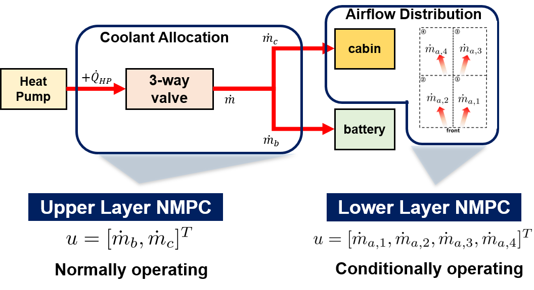
(ii) We introduce a hierarchical control strategy utilizing NMPC with two layers to optimize energy efficiency and proficiently address interruptions from door-opening events. The first component divides the coolant flow through a 3-way valve, while the second, a conditional layer, directs inflowing air into the cabin. This involves deploying a conditional MPC controller specifically activated during door-opening events, with the purpose of reducing the computational burden when door-opening does not occur. This approach enables us to minimize temperature recovery time by precisely regulating air flows.
(iii) Simulation results of our NMPC-based thermal management strategy, alongside benchmark control strategies like rule-based controllers, showcase the effectiveness of our hierarchical control approach, particularly in effectively handling door-opening scenarios critical for maintaining the desired temperature in the cabin.
The remainder of the paper is organized as follows: Section II introduces the ITMS and validated door-opening model. Section III details the hierarchical heating control strategy, emphasizing the primary contribution. Section IV presents case studies comparing our approach with baselines. Section V concludes, summarizing key findings and contributions.
II MODELING
In this section, we introduce our door-opening considered cabin model in detail. The longitudinal dynamics of the vehicle are employed based on the reference [17]. Given space constraints, a brief overview of the coolant cycle is presented here. For further details, refer to our prior work [18], where we developed an EV model with a 150 kW traction motor, a 64 kWh battery pack, and an ITMS, incorporating thermal interaction models.
II-A Cabin Model
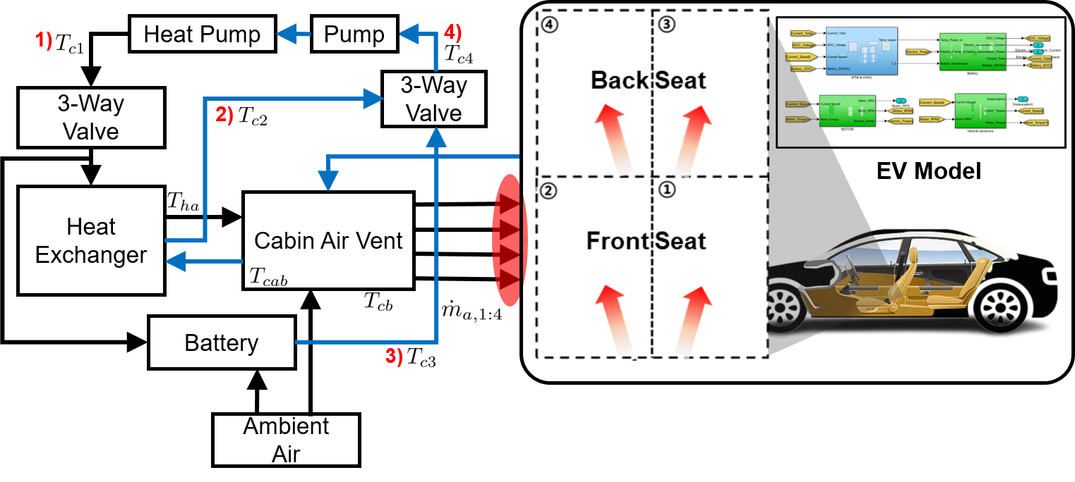
In Fig. 1, the coolant cycle is segmented into four parts: 1) after the heat pump heat exchanger, 2) after the cabin-side heat exchanger, 3) after interaction with the battery, and 4) the combined temperature of 2) and 3). This paper uses the notations , , , and to represent the coolant temperatures of these relevant phases. In consideration of limited space, as highlighted earlier, we opt to omit the detailed temporal evolution formulations for the coolant phases in this paper. This choice is made to center our attention on the main contribution of this paper, which is the cabin model addressing door-opening interruptions.
Firstly, the formulation for the standard cabin model formulations, excluding considerations for door-opening, encompasses its interaction with the cabin body and cold ambient air are expressed as follows:
| (1) | ||||
| (2) |
here, and represent the thermal interaction coefficients of the cabin and cabin body, respectively, while denotes the surface area of the cabin body. and denote heat generation by the occupants in the cabin and the transmitted heat from solar radiation, respectively. Additionally, , , , and stand for the mass of air, cabin body, specific heat capacity of air, and specific heat capacity of the cabin body, respectively. The variable represents the air inflow into the cabin, serving as a decision variable within this model.
The stands for the heated air which flows into the cabin after thermal interaction with coolant at the heat exchanger and its temporal evolution formulation is as follow:
| (3) |
here, stands for the heat transfer coefficient between the inlet air and the coolant in .
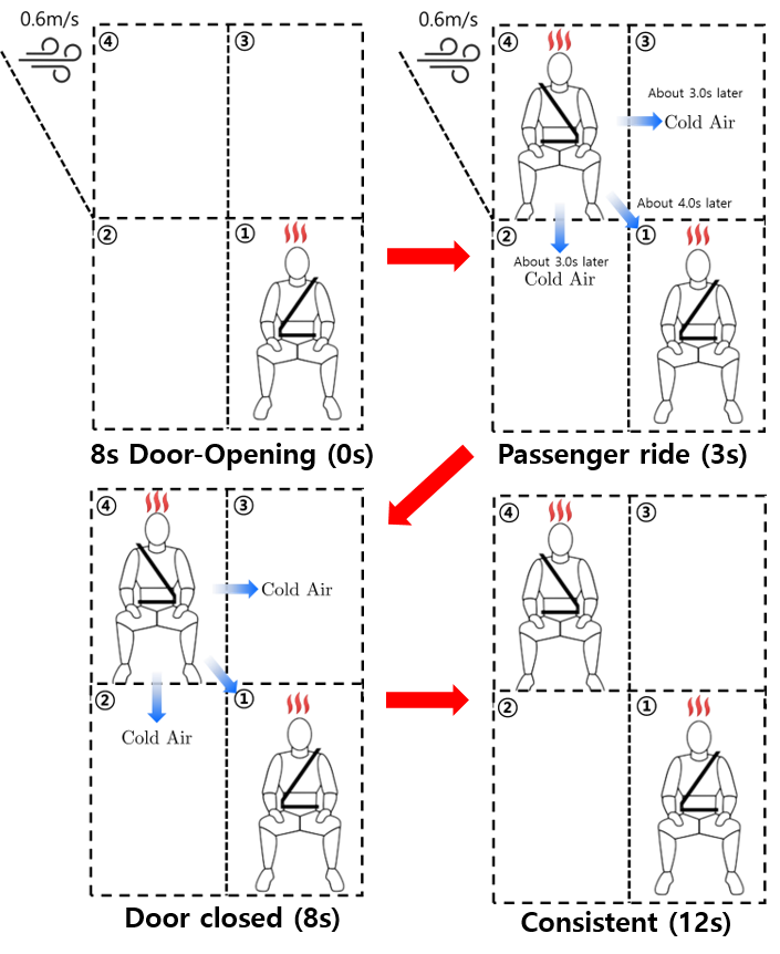
Based on these formulations, we construct separated cabin sections, divided into four distinct parts, to effectively elucidate thermal interactions between sections during door-opening events. The door-opening model, , constructed in this paper, is based on a detailed analysis from a formal study [19] exploring the thermal impact of door-opening in cold climates.
Figure 2 represents the four distinguished sections of the cabin. We assumed that the door-opening occurs in Section 4 in this study. When door-opening occurs, cold air flows into the cabin and that chill propagates to the other sections after 3 seconds, in general. The formulations for the door-opening cabin models in each section, denoted as are as follows:
| (4) |
In this equation, represents the aggregate of additional heat generation and losses for each section, including contributions from occupants and losses due to door-opening. Crucially, this value is a time-varying variable, dependent on time and variable across sections. The variables and represent the surface area of the cabin body and the mass of air for each section, respectively. The value represent the air inflow for each section. Further details regarding this variable will be elaborated upon in Section III.
II-B Model Validation
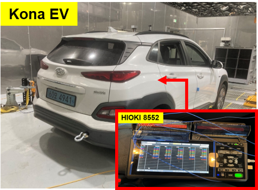
In this subsection, we validated our model with a real car experiment at KATECH, Daegu, South Korea, using a KONA EV by HYUNDAI, mirroring our ITMS model specifications. The experiment used a HIOKI 8552 voltage/temp unit, capable of measuring 30 channels at a 20ms sampling time. Conducted in an environment with -7°C ambient temperature, the experiment targeted a cabin temperature of precisely 23°C, aligning with simulation conditions. Figure 3 displays the vehicle and thermometer used in this validation experiment.
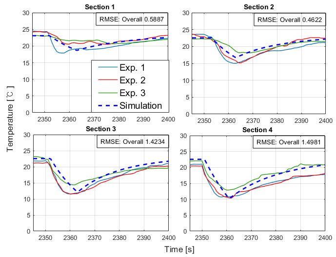
In Fig. 4, the comparison results are shown for three experiment iterations, visually distinguished by blue, red, and green lines. Despite consistent conditions, little variations in starting temperatures were observed across sections in the experimental data.
Sections 3 and 4 exhibit significant temperature drops, with the impact of door-opening in Section 4 notably affecting Section 3 more than Sections 1 and 2. This difference may be attributed to seats hindering cold air propagation between front and back sections. Simulation results align with real-world trends, although it does not consider the air flow complexities. The root-mean-square errors between average experimental data and simulations for these sections are 0.5887, 0.4622, 1.4234, and 1.4981, affirming the model’s accuracy in illustrating thermal interactions.
III NMPC-BASED HIERARCHICAL CONTROLLER DESIGN
In this section, we present the NMPC-based hierarchical ITMS heating control strategy, which consists of two layers as illustrated in Fig. 5. The upper layer controller allocates the coolant to the cabin and battery sides, while the lower layer controller manages the distribution of inflow air to each section.
The upper layer primarily focuses on distributing the coolant to the cabin and battery sides. In this scenario, raising the battery temperature becomes crucial for improving efficiency, especially during vehicle starts in cold climates. This layer operates effectively when there are no interruptions, aiming to elevate the temperature to the target.
However, in situations like door-opening events, interruptions lead to varying temperature statuses in each section, creating discrepancies in passengers’ thermal comfort. To address this, we introduce a hierarchical structure capable of managing inflow air distribution to minimize these discrepancies. The controller presented here lays the groundwork for further development in our upcoming studies.
| subject to | ||||
| (5) |
The cost function comprises two terms: the first term focuses on tracking the set temperature of the cabin with a corresponding weight factor , while the second term addresses the tracking of the battery set temperature with a weight factor . This controller efficiently manages the division of coolant flow, aiming to reduce energy consumption by adequately heating the battery temperature, which enhances the energy efficiency. To effectively regulate the cabin and battery temperatures, we establish maximum and minimum constraints. Additionally, for the development of a rational controller, constraints are imposed on the control inputs. To address the optimal distribution of the inflow air to each section, the second-layer MPC is formulated as follows:
| subject to | ||||
| (6) |
the formulation comprises two distinct terms in the cost function: the first term focuses on tracking the set temperature for each section, while the second term aims to prevent sudden changes in air flow for passenger thermal comfort. Excessive air distribution to a single section can adversely impact passenger thermal comfort, making it an impractical control action. To prevent this and ensure reasonable control, we impose constraints on the control inputs. Additionally, since this controller operates conditionally based on door-opening signals, we set state constraints to effectively prevent substantial temperature drops in specific sections.
Combining these two layers of controllers not only ensures effective management of the cabin temperature but also facilitates a more reasoned approach. This synergistic control system is designed to enhance thermal comfort for passengers, providing a balanced and efficient response to dynamic conditions, such as door-opening events. The integration of these layers creates a comprehensive control framework capable of addressing diverse scenarios and contributing to overall system stability.
IV CASE STUDY
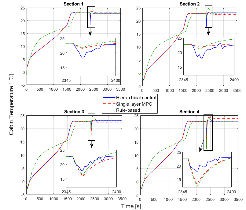
In this section, we present an overview of the results and compare them with different control strategies. We conducted simulations and compared the cabin temperature outcomes for segmented sections utilizing three controllers: the proposed hierarchical controller, a single layer MPC, and a rule-based controller. The single layer MPC controller refers to a controller that solely comprises the upper layer MPC in Fig. 5 and remains fixed on air distribution even when door-opening occurs. This suggests that the results of the single layer MPC precisely match those of the hierarchical controller until the occurrence of door-opening. A comparison between the proposed controller and single layer controller will highlight the necessity of a hierarchical control strategy.
The rule-based controller adheres to the following rules: before the door opens, the heating process primarily focuses on warming the battery for temperature efficiency. The heating status is set according to Eq. (7).
| (7) |
When the condition is met, the controller sets to higher values to focus on the cabin heating. Meanwhile, the air inflow rates remain constant until a new passenger boards. While driving, if a new passenger is detected, each section is heated differently in response to this signal, providing additional heat to the passenger’s specific section.
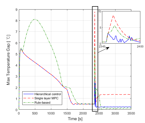
Figure 6 illustrates the heating simulation results for divided sections using the mentioned controllers. In the first and second graphs, the proposed strategy exhibits the most significant temperature drops, while the third and fourth sections show the smallest drop compared to others. While allowing the temperature in the passenger’s section to drop might seem unconventional, it is crucial to understand that our primary objective was to minimize the temperature gap between each section. This aspect can be expanded in our future work by integrating passengers’ thermal comfort throughout the entire vehicle. We anticipate that incorporating a thermal comfort term into the cost function will eliminate this seemingly unconventional result.
In the graph depicting Section 4, where a significant temperature drop is anticipated, the proposed controller demonstrates superior performance. It exhibits a 46.96% reduction in temperature drop compared to the single layer MPC and a 51.33% reduction compared to the rule-based controller.
As depicted in Fig. 7, the proposed algorithm demonstrates the smallest temperature gap between sections during door-opening events. In contrast, the single layer MPC exhibits the largest gap during temperature recovery progress due to the fixed throughout the entire simulation. In this graph, the proposed controller exhibits an 86.4% reduction in temperature gaps compared to the single layer MPC and a 78.7% reduction compared to the rule-based approach. This outcome underscores the significance of effective inflow air control and provides rationale for the development of the hierarchical multi-layered MPC controller presented in this paper. The reduction in temperature gaps between sections presents potential for further development, enabling effective management of multiple passengers’ thermal comfort.
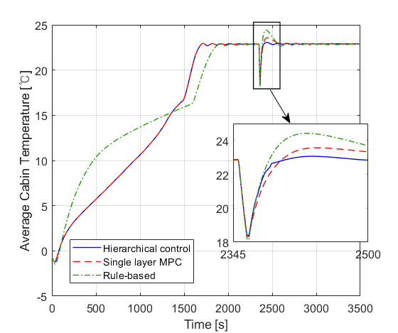
Figure 8 shows the average cabin temperatures for each controller. In this result, although the rule-based controller appears to return the temperature to the set point faster, the proposed control strategy exhibits the smallest overshoot, which can be a significant indicator of successful heating, while the rule-based one shows the biggest overshoot, and the single layer MPC follows closely. Numerically, the proposed controller achieves a 95.17% reduction in temperature overshooting compared to the rule-based approach and an 87.9% reduction compared to the single layer MPC. This indicates that the proposed hierarchical controller outperforms others in minimizing temperature overshoot and achieving swift recovery, particularly in the context of door-opening events.
V CONCLUSIONS
In this study, we developed an integrated thermal management model for EVs, incorporating door-opening scenarios and validating the model through experiments to demonstrate its accuracy. The hierarchical control strategy proposed here showed efficient heating performance, particularly in minimizing temperature drops in the fourth section where the door-opening occurred. While seemingly conflicting results observed a greater temperature drop in the first section compared to other control strategies, this could be adjusted by assigning a larger weight factor in Eq. (III) to prioritize more heat for the driver section. Although our primary focus was on minimizing temperature gaps across all sections, laying the groundwork for future investigations into the thermal comfort of multiple passengers within the vehicle cabin, we suggest that incorporating thermal comfort terms for each section into the cost function could eliminate significant temperature drops in passenger sections. This study establishes a rational research model for a heating strategy accounting for door-opening interruptions, with future endeavors aiming to optimize effective heating while considering individual thermal comfort for passengers in door-opening scenarios. Furthermore, with the foundation of V2X connectivity, there is significant potential for future research in advancing connected vehicle climate control. This aspect holds promising prospects for further exploration in the upcoming research endeavors.
References
- [1] M. Steinstraeter, T. Heinrich, and M. Lienkamp, “Effect of low temperature on electric vehicle range,” World Electric Vehicle Journal, vol. 12, no. 3, p. 115, 2021.
- [2] A. Pesaran, S. Santhanagopalan, and G. Kim, “Addressing the impact of temperature extremes on large format li-ion batteries for vehicle applications (presentation),” National Renewable Energy Lab.(NREL), Golden, CO (United States), Tech. Rep., 2013.
- [3] K. Qian, C. Zhou, Y. Yuan, and M. Allan, “Temperature effect on electric vehicle battery cycle life in vehicle-to-grid applications,” in CICED 2010 Proceedings. IEEE, 2010, pp. 1–6.
- [4] J. Glos, L. Otava, and P. Václavek, “Non-linear model predictive control of cabin temperature and air quality in fully electric vehicles,” IEEE Transactions on Vehicular Technology, vol. 70, no. 2, pp. 1216–1229, 2021.
- [5] K. H. Kwak, Y. Chen, J. Kim, Y. Kim, and D. D. Jung, “Thermal comfort-conscious eco-climate control for electric vehicles using model predictive control,” Control Engineering Practice, vol. 136, p. 105527, 2023.
- [6] M. R. Hajidavalloo, J. Chen, Q. Hu, Z. Song, X. Yin, and Z. Li, “Nmpc-based integrated thermal management of battery and cabin for electric vehicles in cold weather conditions,” IEEE Transactions on Intelligent Vehicles, 2023.
- [7] A. Lahlou, F. Ossart, E. Boudard, F. Roy, and M. Bakhouya, “A dynamic programming approach for thermal comfort control in electric vehicles,” in 2018 IEEE Vehicle Power and Propulsion Conference (VPPC). IEEE, 2018, pp. 1–6.
- [8] M. Konda, T. Hofman, and M. Salazar, “Energy-optimal design and control of electric powertrains under motor thermal constraints,” in 2022 European Control Conference (ECC). IEEE, 2022, pp. 1178–1185.
- [9] M. R. Amini, H. Wang, X. Gong, D. Liao-McPherson, I. Kolmanovsky, and J. Sun, “Cabin and battery thermal management of connected and automated hevs for improved energy efficiency using hierarchical model predictive control,” IEEE Transactions on Control Systems Technology, vol. 28, no. 5, pp. 1711–1726, 2019.
- [10] Q. Hu, M. R. Amini, A. Wiese, R. Semel, J. B. Seeds, I. Kolmanovsky, and J. Sun, “Robust thermal management of electric vehicles using model predictive control with adaptive optimization horizon and location-dependent constraint handling strategies,” IEEE Transactions on Control Systems Technology, 2023.
- [11] S. Zhao, M. R. Amini, J. Sun, and C. C. Mi, “A two-layer real-time optimization control strategy for integrated battery thermal management and hvac system in connected and automated hevs,” IEEE Transactions on Vehicular Technology, vol. 70, no. 7, pp. 6567–6576, 2021.
- [12] M. Ghalkhani and S. Habibi, “Review of the li-ion battery, thermal management, and ai-based battery management system for ev application,” Energies, vol. 16, no. 1, p. 185, 2022.
- [13] E. Luchini, A. Poks, D. Radler, and M. Kozek, “Model predictive temperature control for a food transporter with door-openings,” in 2020 SICE International Symposium on Control Systems (SICE ISCS). IEEE, 2020, pp. 85–91.
- [14] L. Ma, N. Shao, J. Zhang, and T. Zhao, “The influence of doors and windows on the indoor temperature in rural house,” Procedia Engineering, vol. 121, pp. 621–627, 2015.
- [15] M. Hasanuzzaman, R. Saidur, and H. H. Masjuki, “Investigation of energy consumption and energy savings of refrigerator-freezer during open and closed door condition,” Journal of Applied Sciences, vol. 8, no. 10, pp. 1822–1831, 2008.
- [16] D. Marr, M. Mason, R. Mosley, and X. Liu, “The influence of opening windows and doors on the natural ventilation rate of a residential building,” Hvac&r Research, vol. 18, no. 1-2, pp. 195–203, 2012.
- [17] R. Rajamani, Vehicle dynamics and control. Springer Science & Business Media, 2011.
- [18] S. Nam, C. Moon, S. Park, B. Lee, and K. Han, “Design and implementation of comprehensive thermal management verification model for electric vehicles operating in cold climates,” International Journal of Automotive Technology, pp. 1–13, 2024.
- [19] H. NagaNo, T. Sato, I. Kohri, and Y. Yoshinami, “Effect of air exchange due to door opening on the transient thermal environment in a vehicle,” Journal of the Human-Environment System, vol. 19, no. 1, pp. 023–030, 2016.