Graph-Based Convexification of Nested Signal Temporal Logic Constraints for Trajectory Optimization
Abstract
Optimizing high-level mission planning constraints is traditionally solved in exponential time and requires to split the problem into several ones, making the connections between them a convoluted task. This paper aims at generalizing recent works on the convexification of Signal Temporal Logic (STL) constraints converting them into linear approximations. Graphs are employed to build general linguistic semantics based on key words (such as Not, And, Or, Eventually, Always), and super-operators (e.g., Until, Implies, If and Only If) based on already defined ones. Numerical validations demonstrate the performance of the proposed approach on two practical use-cases of satellite optimal guidance using a modified Successive Convexification scheme.
1 Introduction
The widespread approach for optimizing high-level mission planning scenarios generally involves parallel or distributed frameworks requiring to split the problem into several segments, often failing in finding global optimal solutions [YYW+19]. Tasks requiring fast generations may opt for fewer segments and more lenient splitting tolerances in their planning, hence trading for precision. On the other hand, highly accurate trajectories involve increased subproblems with tighter splitting tolerances, leading to longer planning times [WBT21]. In any case, tuning of hyper-parameters (number of segments, tolerance) is an inherent limitation which has to be differently approached from one problem to another. By treating the trajectory as a whole, this issue is alleviated, but at the cost of even larger computational efforts. Generally solved using Mixed-Integer Linear Programming (MILP) or related NP-hard techniques [Ric05], these methods suffer from poor scaling capabilities and their integration into agile autonomous systems with low computational capabilities today still remains out of reach.
Another way of looking at high-level mission planning is from the perspective of logic operators. Derived from the linear temporal logic (LTL) theory [Pnu77], logical operators such as And, Or, Eventually, Always, Until provide a formal language to express complex temporal constraints and objectives in optimization models. In [DM10], Signal Temporal Logic (STL) was introduced as a derivative of LTL to guide simulation-based verification of complex nonlinear and hybrid systems against temporal properties. STL was later extended from verification to optimization to fit within a robust Model Predictive Control (MPC) scheme [RDM+14]. Although enabling more intuitive problem-solving approaches, its underlying MILP baseline showed incompressible limits to its applicability for fast, responsive autonomous systems.
To remedy this, in 2022, Y. Mao, B. Açıkmeşe, et al. [MAGC22] were the first to apply STL to convex optimization [BV04], specifically to the Successive Convexification (SCvx) scheme introduced in [MSA16], and benefit from all its fast and global convergence properties to a local optimum provided convexity assumptions. Signal Temporal Logic was also infused into Machine Learning and Deep Learning [MGFS20], [VCDJS17] as well as reinforcement learning [PDN21]. Furthermore, [LAP23] computed the quantitative semantics of STL formulas using computation graphs and perform backpropagation for neural networks using off-the-shelf automatic differentiation tools. However, supervised and reinforcement learning, and especially applied to trajectory optimization, are black boxes requiring enormous amount of realistic data, which makes them problem dependant, training intensive and has no certification for safety critical missions.
For the present study, inherited from the foundations laid down in [MAGC22] and [LAP23], the aim is to bridge the gap between graph-based Signal Temporal Logic and convexification for optimization problem solving. By accompanying the reader through several examples, arbitrarily complex graphs of STL constraints are being discretized and linearized to fit the convex framework. New super-structure of operators are introduced while numerical simulations show the effectiveness of the proposed approach within a modified Successive Convexification scheme. The layout of this work goes as follows:
-
•
Section 2 presents the STL grammar and its convexification basics;
-
•
Section 3 focuses on each basic logical operator individually;
-
•
Section 4 presents operator nesting and proposes a convexification process based on graphs;
-
•
Section 5 presents new operators which can be derived from existing ones, therefore creating super-operators and getting closer to real-world operations;
-
•
Section 6 presents simulation results of optimization problems containing real-world operating constraints;
-
•
Section 7 finally draws conclusions on this work.
2 STL Grammar and Convexification
This section presents the STL grammar (see also [MAGC22]) and the associated convexification process in the context of a general convex optimization problem of type:
| (1) |
subject to the discrete dynamics:
| (2) |
as well as STL type constraints being introduced in the present work. Additional convex constraints of inequality and equality types can also be implemented in the general vector format:
| (3) |
2.1 STL Grammar
Signal Temporal Logic uses a specific grammar that is being recalled in this section. The following notations are functional to the STL grammar:
-
•
and : state and control vectors at time instance ;
-
•
or : examples of STL predicates found throughout the paper (always expressed in terms of inequality, an equality being a double inequality);
-
•
: generic function of the state and control vectors;
-
•
: Boolean predicate whose truth value is determined by the sign of the evaluation of (i.e. , 0 otherwise).
Examples of STL formula could be a function expressing the command variable greater than a certain value or expressing the distance between two objects lower than a threshold value. Table 1 presents mathematical key words used in the sequel of this paper and STL operators as building blocks of logical constraints.
| Mathematical Symbol | Meaning |
|---|---|
| Negation | |
| There exists | |
| For all | |
| Implies | |
| If and Only If | |
| Satisfies | |
| Is Equivalent |
| STL Operator | Symbol |
|---|---|
| And | |
| Or | |
| Eventually | |
| Always | |
| Exclusive Or | |
| Until |
The formal semantics of predicates or/and with respect to a trajectory are defined as follows:
-
•
A trajectory at time , denoted satisfies a predicate if and only if the associated function at time is positive:
(4) -
•
A trajectory at time satisfies the negation of a predicate if and only if the opposite trajectory satisfies :
(5) -
•
A trajectory at time satisfies the conjunction (respectively disjunction ) if and only if the signal at time satisfies the STL predicates and (respectively or ):
(6) (7) -
•
A trajectory satisfies Eventually () between time and if and only if there exists at least one time in that interval where the predicate is satisfied:
(8) -
•
A trajectory satisfies Always () between time and if and only if the predicate is satisfied for each time between the interval :
(9)
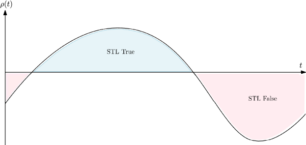
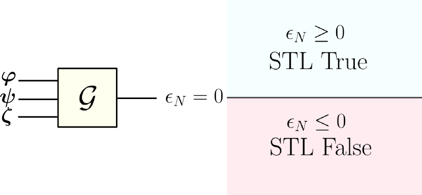
2.1.1 STL Margin Measure
In the above STL Eqs. (4) to (9), the result is a Boolean: either the property is True, or False. In order to gain more insight, a margin function is introduced to better classify an STL expression. The margin function defines the truth of the STL formula as shown in Fig. 1. This margin function is computed using minimum and maximum functions for the STL operators introduced in Table 1 and used in Eqs. (4) to (9).
Let us consider a practical example to better illustrate the interest of the margin function . By denoting the position of an autonomous system as , the condition states that at time the system remains at a distance greater than a certain value from an obstacle located at the reference frame’s origin. In that case, defining a margin function such that , the security condition is satisfied at time t if and only if is positive at . STL formulas (4) to (9) can be expressed as follows, in terms of margin semantics using margin functions.
The complete robust semantics for Eq. (4) is given by:
| (10) |
Margin function for the negation of a property of the Eq. (5) is given by:
| (11) |
Margin function of Eq. (6) as conjunction satisfies the following minimum property in terms of margin functions of and :
| (12) |
Instead, margin function of Eq. (7) as disjunction satisfies the following maximum property in terms or margin functions of and :
| (13) |
Margin function of Eq. (8) (involving constraint Eventually () True between time and ) is positive when the maximum of the constraint margin function is positive in the interval:
| (14) |
Margin function of Eq. (9) (involving constraint Always () True between time and ) is positive when the minimum of the constraint margin function is positive in the interval:
| (15) |
2.2 STL Convexification
The convexification process is made of three steps. First, discretization to make the problem suitable for numerical evaluations and implementation on computers. Then, the second step is linearization to approximate nonlinear functions and work with convenient linear methods. Finally, the third step is to concatenate the linearizations into a linear system of equations, being a suitable input for optimization problem solvers. This section discusses these three steps in greater details.
2.2.1 Discretization
As it was seen in Section 2.1.1, the margin of the operators are functions of time and derived from and functions. So, to model this in the discrete world, new variables (scalars), denoted as STL-variables, representing the margin (which is a scalar) evaluated at each time step, are introduced:
| (16) |
The STL-variable vector augments the state vector of the optimization variables:
| (17) |
to give:
| (18) |
The goal is to replicate the behavior of the max or min functions over time intervals . The extremum is initialized at the first value of the interval and propagates through it. The obtained value at the end of the interval is kept until the end. It follows:
| (19) |
where is a general function representing the margin, e.g., functions or .
Between times and , the STL-variable vector is now defined as a sequence of scalar variables following the discrete dynamics:
| (20) |
The margin function, in turn, depends on the dynamics of the system under control:
| (21) |
2.2.2 Linearization
Now, the STL-variables are defined over the whole time horizon to follow the continuous definition of the margin function. In particular, the functions and are not linear as function of the other STL-variables, not even differentiable (indeed the maximum and minimum function have sharp edges at the flips). Function is in general not linear as well (e.g. when asking for a distance between an object and an obstacle being greater that a threshold, the norm function is involved). These kinds of functions are not straightforwardly implementable in a standard convex optimization algorithm. A linearization step is then performed to cope with this framework.
Let us assume that function is differentiable. In that case, it would be desired to consider the STL-variables appearing linearly to build a linear system of equations. Using the chain rule (derivation of function composition), the approximation to the first order of the Taylor expansion leads:
| (22) |
where the notation for any general variable represents the reference of at time (e.g. either of the initialization or the last optimal iteration). Introducing the zero order term:
| (23) |
Dropping the reference notation for the gradients in the following part of the paper, for the sake of conciseness, one finally gets:
| (24) |
Equation (24) is now linear in the STL-variables and in the dynamic state variables . Function , when equal to or , is not differentiable. However, as proposed in [MAGC22], it can be approximated with smoothed functions ( and for and respectively). Function and are defined as follows (see also Fig. 2 depicting an example):
| (25) |
where is the smoothing function:
| (26) |
dependent on its smoothing gain .
As stated in Eq. (24), partial derivatives of the margin functions are essential to define the STL-variable dynamics:
| (27) |
| (28) |
Caution has to be taken by the reader since . Indeed, function is defined as:
| (29) |
where is the smoothing function:
| (30) |
dependent on its smoothing gain .
Partial derivatives of the margin function are the following:
| (31) |
| (32) |
These partial derivatives will allow to implement the derivatives of with respect to its variables as seen in (24).
In cases where the margin functions might not be differentiable at certain points (e.g., the norm function is not differentiable at 0), a null gradient can, for instance, be automatically introduced when performing the computation at these singular points. Of course, the smaller the , the better the approximation (in practice, not thinking about differentiability, seemed of no concern in this work). Maybe some edge cases could be found in highly nonlinear settings, but with a usual step size, the vicinity of the flips is rarely, not to say never, encountered in practical applications. The takeaway is probably that that there is a parameter which can smoothen the dynamics if needed. In the following, the input of will be omitted for conciseness.

2.2.3 Convex Framework
After discretizing and linearizing the robust semantics of the STL-formulas, the final step is to transform the STL-variable dynamics equations into a convex matrix form of type , where:
-
•
is defined as the state-transition matrix;
-
•
is the augmented optimization vector composed of the state optimization variable vector and of the STL-variable vector );
-
•
is the vector independent on the optimization variables.
To define these three convex framework elements on the basis of the discrete and linearized dynamics of Eqs (19) and (24), the following mathematical notation are used:
-
•
is an identity square matrix of size ;
-
•
is a column vector of length with all its elements equal to 0;
-
•
is a zero matrix with rows and columns;
-
•
is a column vector of length with all its elements equal to 1;
-
•
is a diagonal concatenation of blocks, each equal to the row vector ;
-
•
is a diagonal concatenation of blocks, equal to for .
Compact convex formulation is based on the following definitions:
-
1.
For matrix :
(33) with:
(34) (35) (36) -
2.
For vector :
(37) -
3.
For vector :
(38)
This linear system of equations can then be concatenated with the other physical dynamics linear constraints to obtain an augmented optimization problem, which will then be fed to the convex optimization solver (e.g., second-order cone, semi-definite).
Finally, it remains a very last constraint, which is actually the most natural and important. Let us recall that the STL constraint will be satisfied if and only if the margin function is positive. This can be enforced by asking the last time step of the STL variable to be positive:
| (39) |
Note that all the constraints are made to specifically arrive to this one.
3 Isolated STL Operators
This section presents the STL operators one by one as introduced in [MAGC22]. In Section 4, nesting of these STL operators considered as building blocks will be presented. This paper introduces the classification of the four main operators And, Or, Eventually, Always as operators of type Bridge Operator or Flow.
-
•
An operator is of Bridge type when it connects two inputs and generates only one output. And and Or are examples of Bridge operators.
-
•
An operator is of Flow type when it is connected to a single input and generates a single output. Eventually and Always are examples of Flow operators.
3.1 Bridge Operators
3.1.1 And
Let and , be two predicates. The conjunction operator between and is shown in Fig. 3, represented by a graph.
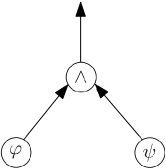
In terms of robust STL semantics, the margin function of the conjunction operator can be expressed as a minimum function:
| (40) |
The discretization gives
| (41) |
Defining as (respectively ) the state variable vector used to write predicate (respectively ), the linearization provides:
| (42) |
In general, the states considered by the two margin functions are completely different. For instance, one could use the positions, while the other one the attitude. In that case, they would have to be positioned differently in the STL matrix , easily made with an automated routine.
The terms of the compact convex formulation becomes:
-
1.
For matrix :
(43) -
2.
For vector :
(44) -
3.
For vector :
(45)
Taking the analogy with electric circuits, the system would look like Fig. 4:

3.1.2 Or
Let and , be two predicates. The disjunction operator between and is shown in Fig. 3, represented by a graph.
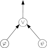
In terms of robust STL semantics, the margin function of the disjunction operator can be expressed as a maximum function:
| (46) |
The discretization gives:
| (47) |
Defining as (respectively ) the state variable vector used to write predicate (respectively ), the linearization provides:
| (48) |
In general, the states considered by the two margin functions are completely different. For instance, one could use the positions, while the other one the attitude. In that case, they would have to be positioned differently in the STL matrix , easily made with an automated routine.
The terms of the compact convex formulation becomes:
-
1.
For matrix :
(49) -
2.
For vector :
(50) -
3.
For vector :
(51)
Taking the analogy with electric circuits, the system would look like Fig. 6:

3.2 Flow Operators
3.2.1 Always
The Always operator is an operator of flow type, it asks for a property to always be True inside of a time window, which can cover the whole simulation. The Always operator is shown in Fig. 7 represented by a graph.
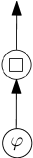
In terms of robust STL semantics, the margin function of this operator can be seen as a recurrent conjunction active at each time step of the time window. The discretization of this operator gives:
| (52) |
The terms of the compact convex formulation have the same expression as the ones in Eqs (33)-(38) with:

3.2.2 Eventually
The Eventually operator is an operator of flow type, it asks for a property to be True at least once inside of a time window, which can cover the whole simulation. The Eventually operator is shown in Fig. 9 represented by a graph.
In terms of robust STL semantics, the margin function of this operator can be seen as a recurrent disjunction active at each time step of the time window. The discretization of this operator gives:
| (55) |

4 Nested STL Operators
Nested (i.e., concatenated) STL operators can be used to express complex constraints. This section presents a method to deal with nested STL operators based on graphs. In a graph representing a complex logic expression, the roots (i.e., the first generation parents) are all the predicates of the expression.
The top node of the graph (i.e., the youngest child) must be an operator of Flow type (e.g., Always or Eventually).
This means that, for example, at the very top of the graph, a Bridge expression as is not accepted. To be more precise, a Bridge operator always has to be attached to a Flow operator above it (e.g., to form . This allows to obtain a unequivocal output that does not lead to misunderstandings.
Following this logic, it is possible for each operator to only look at one child down the tree and there is a general formulation to connect them to the rest of the tree.
In the following, the naming conventions of STL variables follows the order of the Greek alphabet the higher in the tree the operator is.
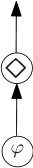
4.1 Nested Flow Operators
A Flow type operator is, by definition, connected to a single input. This is the case for the operator with STL variable vector in Fig. 11. The input Flow type operator can either be the output of another STL operator (e.g., or ), or a simple predicate (e.g., ).
The equations governing the transition at the Flow operator level are the following for the case represented in Fig. 11(a) and 11(b) respectively:
| (58) |
| (59) |
In the above expressions
-
•
is the space of the parent node associated to STL variable ;
-
•
is the space of all the STL variables of all the STL complex expressions;
-
•
is the root predicate space.
For instance, if the Flow operator is connected to an STL expression (e.g., ) as in Fig. 11(a), then . On the other hand, if the flow is directly linked to the predicate as in Fig. 11(b), then .
In cases where the time windows do not cover the whole simulations, the three cases as shown in Eq. (52) or (55) are being used. They are not written again for conciseness.
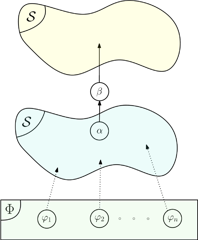
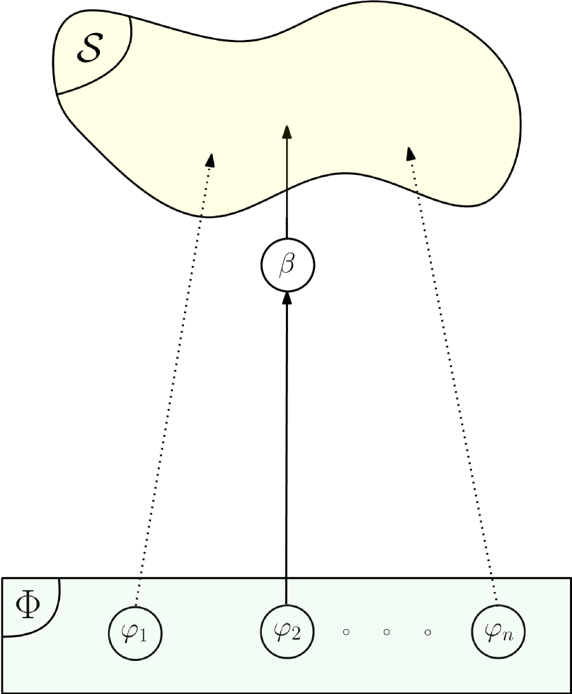
4.2 Nested Bridge Operators
General graphs containing a Bridge type operator with STL variable vector are show in Fig. 12.
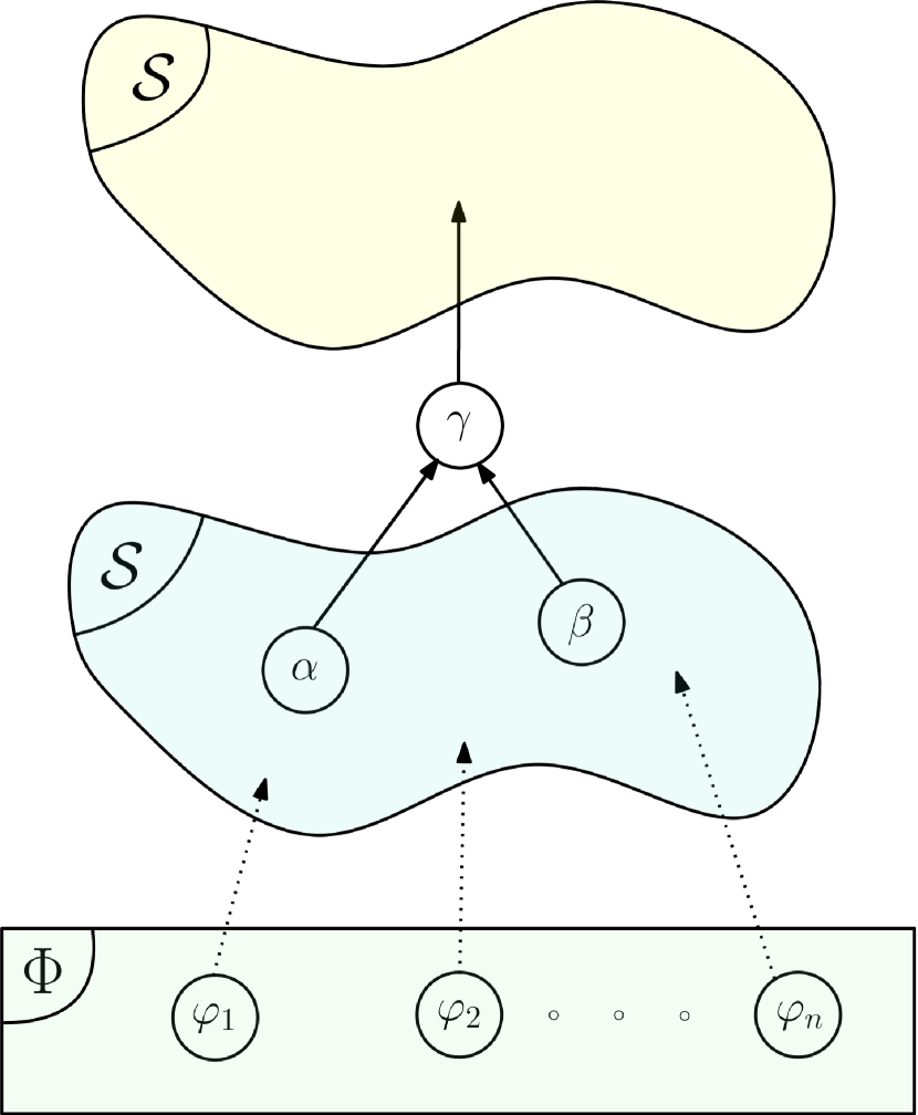
The equations governing the transition at the Bridge operator level are the following for the four cases represented in Fig. 12:
| (60) |
| (61) |
| (62) |
| (63) |
In the above expressions
-
•
(respectively ) is the space of the left (respectively right) parent node associated to STL variable ;
-
•
(respectively ) is the state vector of the left (respectively right) predicate;
-
•
(respectively ) is the margin function of the left (respectively right) STL expression.
4.3 General Nesting
4.3.1 Backward Propagation
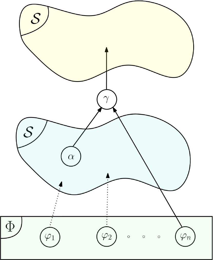
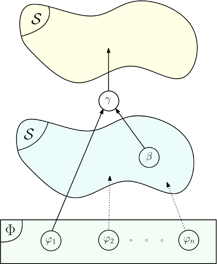
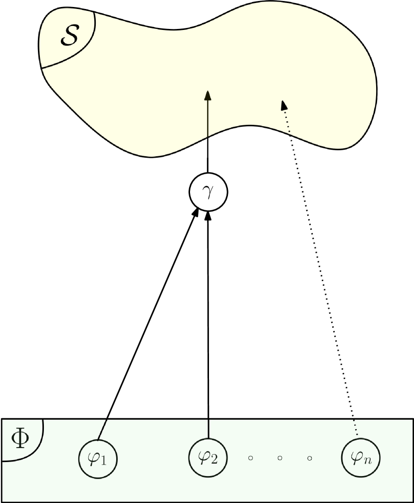
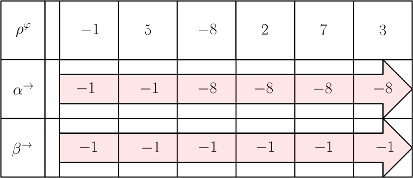
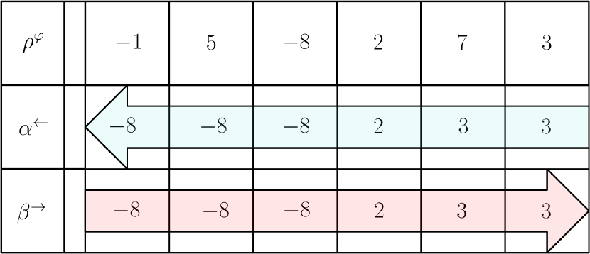
A very important aspect of general nesting is how the margin function is transmitted from each operator to the next one above it. In the previous section, when dealing with a single operator, a forward propagation of the STL variables was performed (i.e., . In the general case, with nesting operators, backward propagation plays a major role in preventing loss of information. To visualize the concept, let us consider the following nesting example:
| (64) |
represented in Fig. 13, where the notations and are the STL variables associated to their respective operators. To illustrate the concept, let assume that the example result is True during the last two time steps, i.e., margin function is eventually always positive for these steps. As always, the STL variable at the last time step must be positive. One notices that the backward propagation of the margins preserves the Boolean conclusion (i.e., the property is True), information being lost at the first negative value in case of forward propagating due to the nesting of and functions.
Another more complex nesting will be presented in Sec. 4.3.2 to build up intuition before presenting the general rules in Sec. 4.3.3.
4.3.2 Until Operator
Until operator, represented with notation , and as presented in [MAGC22], is an operator that checks if a predicate is always True when another predicate triggered True. When taking a closer look at it, can be constructed as a nesting of basic operators and written as follows:
| (65) |
On the other hand, when one reads the sentence When would trigger True, had to have always been True before, a notion of the history of appears. Therefore, one can state that is specifically interested in the history of . For this reason, the Until operator could be constructed also as follows
| (66) |
New notation are introduced to take into account temporal direction in the property validity and in the propagation
-
•
indicates Always before;
-
•
indicates Always after;
-
•
indicates that STL variable is propagated forward because interested in the past (case of all of what has been done in this paper so far as well as in [MAGC22]);
-
•
indicates that STL variable is propagated backward because interested in the future.
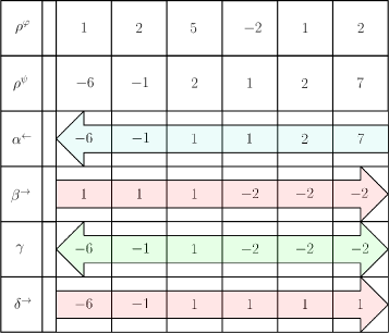
Another example using Until operator is depicted in Fig. 14 and represented as follows:
| (67) |
This nesting operator is equivalent to the following expression highlighting the propagation direction of the STL variables:
| (68) |
It is recalled that the naming conventions of STL variables follows the order of the Greek alphabet the more external or high in the tree the operator is. Here, the sign of respects the given trajectory.
4.3.3 General Formulation
To built a general formulation, about the propagation the following rules can be considered on its direction:
-
•
If interested in what happened before when the operator triggers, perform a forward propagation;
-
•
If interested in the future when the operator triggers, perform a backward propagation;
-
•
Bridges are not affected by propagation direction;
-
•
The last node is computed using a forward propagation in any case.
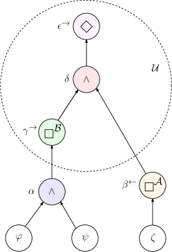
Now that the building blocks are generalized in any position of the tree, full generalization can take place as depicted in Fig. 15.
Let us define the generic operator (or node) of index , the Bridge operator set, the Flow operator set, the root predicates. One then gets
| (69) |
where
-
•
and are respectively the STL variables associated to the Flow and Bridge operators at position and time step ;
-
•
are the Jacobian matrices associated to each operator in the tree at time step ;
-
•
(respectively ) are the parent operator (respectively child operator) of node (it must be noted that for a predicate, by definition at the bottom of the tree, this coincides exactly with the margin function of the states throughout the trajectory);
-
•
the temporal interest of Flow type node , being equal to for After and for Before;
-
•
the empty set.

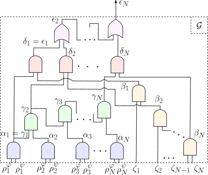
Now, since all the equations are linearized, and since an STL variable solely depends on its parents, it is possible to write the entire constraint using block matrices and vectors. As example, the following nested operator is considered:
| (70) |
In reference to Fig. 16, the entire state-transition matrix has the following structure
| (71) |
with and defined following the theory presented in Sections 3 and 4. Finally, on top of this block-matrix equality, the inequality is added.
Graph representation of Fig. 16 can also be seen from the point of view of an electronic circuit, as shown in Fig. 17(a) and Fig. 17(b) (condensed form). Both representations are equivalent. From several predicates, the output is a number. Its sign defines the validity of the whole constraint.
5 Derived Operators
This section presents three more operators which can be expressed in function of the building blocks already defined. They can serve as a more visual way of modeling a problem by regrouping operators together.
5.1 Implies ()
Implies () can be considered as a bridge operator linking two predicates and . Using the STL grammar the Implies operator can be expressed as follows:
| (72) |
One should just be careful in what they mean when using Implies. Eq. (72) logically means either is False, or, and are True at the same time. This detail can be of great use to simplify graphs.
5.2 If and Only If ()
If and Only If () can be considered as a double implication. Using the STL grammar it can be expressed as follows:
| (73) |
5.3 Exclusive Or ()
Operator Exclusive Or () can be considered as a variant of the inclusive disjunction. It is also the negation of operator If and Only If for the De-Morgan’s law. Therefore, operator can be defined either as a nesting of disjunctions and conjunctions, or as a negation of the equivalence:
| (74) |
5.4 Other Extensions
Defining new operators can be made using previously defined ones in the same philosophy as for Until. Other ideas could be neither nor, exclusive negation or, negative and, or maybe more complex operations like or . Extensions can be created and then used as a block by itself to form more complex logic, hence manipulating super-operators and getting closer to real-world operations.
6 Applications
This section presents two examples of STL constraints used in the context of the satellite trajectory optimization. The modified successive convexification scheme is presented in detail in Section 6.2, implemented for two satellite rendezvous mission applications and discussed in Sections 6.3 and 6.4.
6.1 Problem Setup
As general definition of a satellite rendezvous mission, one satellite (named as chaser) has to dock to another one (named as target). Here, the target is in a circular geostationary orbit around the Earth. The chaser has a mass of 1000 kg and it is initially at coordinates [-2000, 500, 200] m in an orbital frame centered in the target position and with a null relative velocity. The problem is of minimum-fuel optimization over a finite horizon of 5000 s. The maximum allowed thrust of the chaser is 1 N. The simulations were performed using Matlab R2021a and the Mosek solver [ApS23]. The initial trajectory was obtained with zero thrust (i.e., it is a free drift propagation). All the details of this problem statement can be found in [CLL+23].
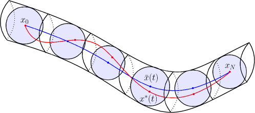
6.2 Modified Successive Convexification Algorithm
Since the problem is in a convex form, the choice was made to use the powerful Successive Convexification (SCvx) framework which extends Sequential Convex Programming (SQP) using trust regions (shown on Fig. 18) for improved performance [MSA16]. The algorithm, which is a modified version of the one in [CLL+23] is presented in Algorithm 1.
To integrate STL constraint in the trajectory optimization problem, the following hypotheses have been assumed.
-
•
As explained in Section 2.2.2, the constraints are functions of the reference trajectory appearing in the zero order term and in the evaluations of the gradients of the linearization. Therefore, a new optimal solution is only optimal with respect to the reference trajectory. To make sure that the new optimal solution really satisfies the STL constraint, the idea is to compute the margin of the STL constraint with the new updated optimal values. This is not a constraint anymore since optimization is already done for this iteration, but a model-checking step. Note that, as the solution converges, this check is less and less important (indeed the reference becomes closer to the new optimal trajectory).
-
•
The cost function to minimize is modified from
(75) to
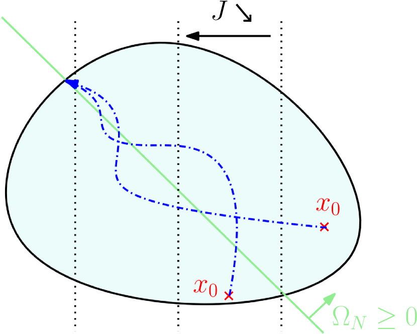
(76) With respect to the energy , the additional second term is function of the STL variable associated to the last time step of the last child at the top of the graph, and of its associated weight . As a design choice for the cost function, it was decided for to increase its weight negatively until a first solution satisfying the STL constraint is found. Indeed, to minimize with , has to be positive (i.e., constraint satisfied). After that, as long as the STL constraint stays True (, is increased, getting closer to zero from negative value, in orde to give more importance to the other objectives as the energy minimization. When becomes negative, the STL constraint becomes False by construction and more importance is again given to the STL constraint, in order to converge to the STL plane while minimizing the energy to find the optimal solution (see Fig. 19 for a graphical representation).
-
•
Moreover, it is also possible to play on the trust radius (see Fig. 18). The radius is increased until a solution satisfying the STL constraint is found, then is shrinks down to help convergence.
The modifications to the Successive Convexification algorithm present in [CLL+23] are in red within Algorithm 1’s description:
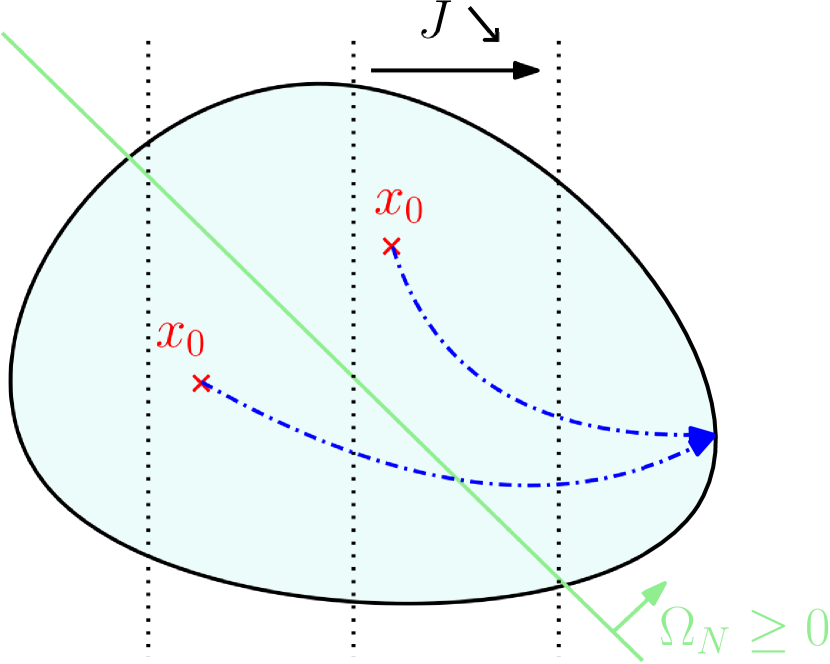
The theoretical behavior of the solution when adding the STL is shown in Fig. 19. In the case of a contradiction between satisfying the STL constraint and minimizing the cost (most relevant case, depicted in Fig. 19(a)), the iterations will converge to the STL plane , while minimizing the cost. In the other case (depicted in Fig. 19(b)), when the natural optimal solution is also fulfilling the STL requirement, the solution converges to the minimal cost, satisfying the STL constraint but not lying on its plane.
6.3 First Example: Safety Spacing in a Satellite Rendezvous Mission
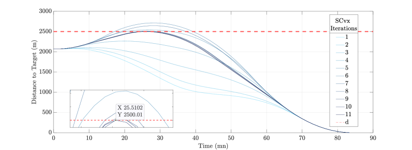
In the first example, let us imagine that certain sensors (e.g., GPS or lidar) during the approach experience a failure. In that case, a possible safety maneuver to prevent collision to the target could be for the chaser to first go outside of a safety sphere around the target before trying to approach and dock it again. While maintaining the same other constraints and objectives, this constraint was modeled as Eventually get outside of a circle of radius , or, using the STL grammar, as:
| (77) |
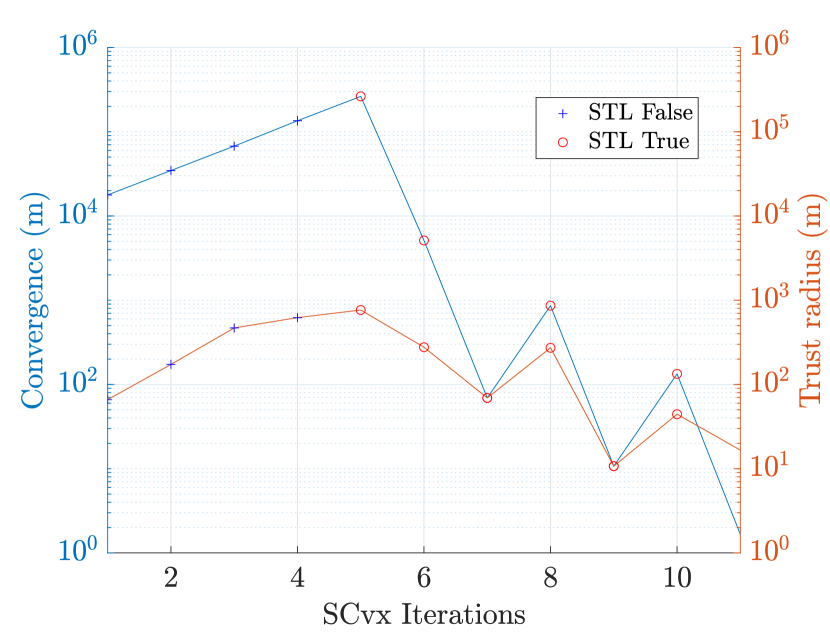
where is the relative position vector between the chaser and the target in the relative orbital frame, and is the radius of the safety sphere. The iterations of the successive trajectories can be seen in Fig. 20. As one could guess, the optimal trajectory tangents to the safety sphere before going back and dock. In this context, convergence value is defined as:
| (78) |
while trust radius is a standard constraint of the SCvx algorithm, written for each iteration as:
| (79) |
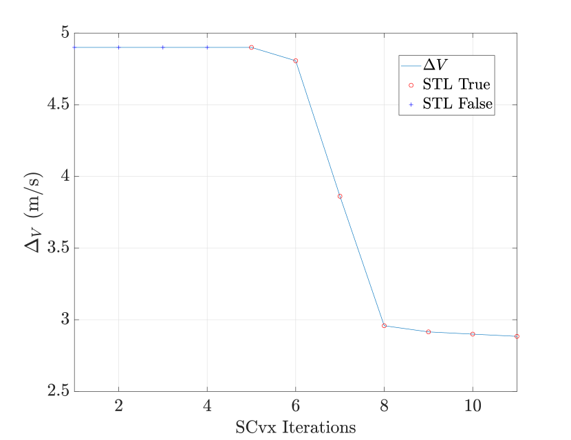
with the optimal value of the position and its reference value (i.e., the previous optimal solution). Fig. 21(a) shows convergence (with a threshold of m) and trust radius (no specific threshold) while the V representing the fuel consumption is observed in Fig. 21(b). The minimum-fuel optimal solution is found in two main steps. First, a feasible solution is obtained where the STL constraint is satisfied. From that point on, the solution is adjusted to keep satisfying the STL constraint, but this time giving more and more importance to the other objective (i.e., energy minimization).
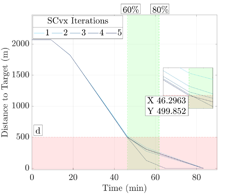
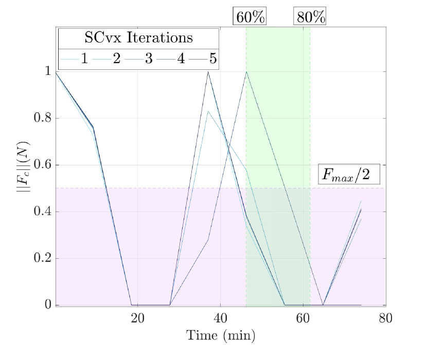
6.4 Second Example: Slow Approach in a Satellite Rendezvous Mission
The second example focuses on a nesting operator using a Bridge and a Flow operator. The objectives id that between 60% and 80% of the transfer time, the relative distance between target and chaser is always less than m, and that the norm of the thrust vector is below the half of its maximum value of 1 N. Using the STL grammar, these constraints can be formalized as follows:
| (80) |
Fig. 22(a) shows the distance of the chaser to the target over time. As one would think, the iterations converge to the threshold at one of the time bounds. The thrust norm over time is represented in Fig. 22(b). The iterations converge meeting the constraint.
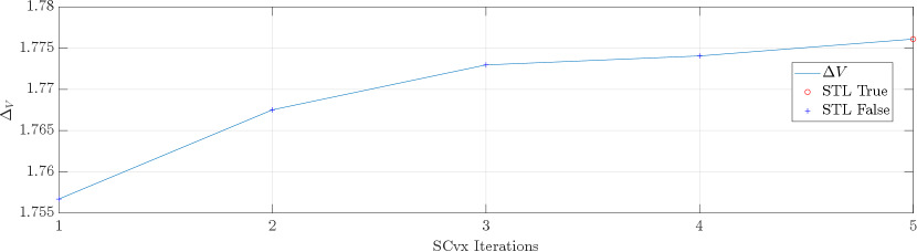
Then, in Fig. 23, the evolution of the fuel consumption is shown at each iteration. It increases until the STL constraint becomes positive.
7 Conclusion
In this work, an end-to-end methodology was presented to be able to take into account arbitrarily-complex Signal Temporal Logic constraints in optimization problem solving. It was shown that basic logic operators such as Or, And, Eventually, Always can be nested together, discretized and linearized to fit powerful convex frameworks. Moreover, graph-based STL formalism is well suited for the construction of super-operators, which, in turn, ease the understanding and the design of complex high-level mission scenarios and pave the way towards realistic agile operations. Using a modified Successive Convexification scheme, two examples were discussed in the context of the safety in autonomous spacecraft rendezvous missions. The results demonstrated high precision and fast convergence properties.
8 Acknowledgment
This paper is part of a Ph.D. work in progress at ISAE-SUPAERO, funded by the IRT (Technological Research Institute) of Saint-Exupéry, in the context of the RAPTOR project (Robotic and Artificial intelligence Processing Test on Representative target) for satellite rendezvous missions, in collaboration with Thales Alenia Space.
References
- [ApS23] MOSEK ApS. The MOSEK optimization toolbox for MATLAB manual. Version 10.0., 2023.
- [BV04] Stephen Boyd and Lieven Vandenberghe. Convex Optimization. Cambridge University Press, March 2004.
- [CLL+23] Thomas Claudet, Jérémie Labroquère, Damiana Losa, Francesco Sanfedino, and Daniel Alazard. Successive convexification for on-board scheduling of spacecraft rendezvous missions. ESA GNC, 2023.
- [DM10] Alexandre Donzé and Oded Maler. Robust satisfaction of temporal logic over real-valued signals. In Krishnendu Chatterjee and Thomas A. Henzinger, editors, Formal Modeling and Analysis of Timed Systems, pages 92–106, Berlin, Heidelberg, 2010. Springer Berlin Heidelberg.
- [LAP23] Karen Leung, Nikos Aréchiga, and Marco Pavone. Backpropagation through signal temporal logic specifications: Infusing logical structure into gradient-based methods. The International Journal of Robotics Research, 42(6):356–370, 2023.
- [MAGC22] Yuanqi Mao, Behcet Acikmese, Pierre-Loic Garoche, and Alexandre Chapoutot. Successive convexification for optimal control with signal temporal logic specifications. In Proceedings of the 25th ACM International Conference on Hybrid Systems: Computation and Control, HSCC ’22, New York, NY, USA, 2022. Association for Computing Machinery.
- [MGFS20] Meiyi Ma, Ji Gao, Lu Feng, and John Stankovic. Stlnet: Signal temporal logic enforced multivariate recurrent neural networks. Advances in Neural Information Processing Systems, 33:14604–14614, 2020.
- [MSA16] Yuanqi Mao, Michael Szmuk, and Behçet Açıkmeşe. Successive convexification of non-convex optimal control problems and its convergence properties. In 2016 IEEE 55th Conference on Decision and Control (CDC), pages 3636–3641, 2016.
- [PDN21] Aniruddh G Puranic, Jyotirmoy V Deshmukh, and Stefanos Nikolaidis. Learning from demonstrations using signal temporal logic in stochastic and continuous domains. IEEE Robotics and Automation Letters, 6(4):6250–6257, 2021.
- [Pnu77] Amir Pnueli. The temporal logic of programs. 18th Annual Symposium on Foundations of Computer Science (sfcs 1977), pages 46–57, 1977.
- [RDM+14] Vasumathi Raman, Alexandre Donzé, Mehdi Maasoumy, Richard M. Murray, Alberto Sangiovanni-Vincentelli, and Sanjit A. Seshia. Model predictive control with signal temporal logic specifications. In 53rd IEEE Conference on Decision and Control, pages 81–87, 2014.
- [Ric05] Arthur Richards. Trajectory optimization using mixed-integer linear programming. 05 2005.
- [VCDJS17] Marcell Vazquez-Chanlatte, Jyotirmoy V Deshmukh, Xiaoqing Jin, and Sanjit A Seshia. Logical clustering and learning for time-series data. In Computer Aided Verification: 29th International Conference, CAV 2017, Heidelberg, Germany, July 24-28, 2017, Proceedings, Part I 30, pages 305–325. Springer, 2017.
- [WBT21] Changhao Wang, Jeffrey Bingham, and Masayoshi Tomizuka. Trajectory splitting: A distributed formulation for collision avoiding trajectory optimization. In 2021 IEEE/RSJ International Conference on Intelligent Robots and Systems (IROS), pages 8113–8120, 2021.
- [YYW+19] Tao Yang, Xinlei Yi, Junfeng Wu, Ye Yuan, Di Wu, Ziyang Meng, Yiguang Hong, Hong Wang, Zongli Lin, and Karl H. Johansson. A survey of distributed optimization. Annual Reviews in Control, 47:278–305, 2019.