Generation of neutron Airy beams
Abstract
The Airy wave packet is a solution to the potential-free Schrödinger equation that exhibits remarkable properties such as self-acceleration, non-diffraction, and self-healing. Although Airy beams are now routinely realized with electromagnetic waves and electrons, the implementation with neutrons has remained elusive due to small transverse coherence lengths, low fluence rates, and the absence of neutron lenses. In this work, we overcome these challenges through a holographic approach and present the first experimental demonstration of neutron Airy beams. The presented techniques pave the way for fundamental physics studies with Airy beams of non-elementary particles, the development of novel neutron optics components, and the realization of neutron Airy-vortex beams.
pacs:
Valid PACS appear hereI Introduction
In 1979, Berry and Balazs showed that there exists a solution to the potential-free Schrödinger equation in the form of an Airy wave packet that is diffraction-free and manifests a form of self-acceleration Berry and Balazs (1979). Afterwards, 1D Airy states appeared in several hallmark neutron experiments, albeit always associated with a gravitational potential Greenberger (1980); Greenberger and Overhauser (1979); Gibbs (1975); Nesvizhevsky et al. (2000, 2002); Abele et al. (2009). Greenberger offered a general physical interpretation of the nondispersive Airy wave packet according to Einstein’s equivalence principle: the Airy wave packet is the stationary state solution for a free particle falling in a gravitational field, equivalent to a free falling reference frame in which the Schrödinger equation is force-free Greenberger (1980). These concepts were applied to the Colella, Overhauser and Werner (COW) experiment, where a neutron interferometer was used for the first experimental observation of gravity’s influence on a quantum particle Colella et al. (1975); Greenberger and Overhauser (1979). Airy functions also appeared in the ‘quantum bouncer’ where a particle in a gravitational potential is reflected from a perfect mirror Gibbs (1975), which led to the observation of bound neutron quantum states in Earth’s gravitational potential Nesvizhevsky et al. (2000, 2002); Abele et al. (2009).
Over the last 20 years, significant progress has been made in the experimental generation and detection of free space propagating Airy beams and structured waves in general Rubinsztein-Dunlop et al. (2016); Bliokh et al. (2023). Optical Airy beams were first produced using a spatial light modulator that imprinted a cubic phase profile onto a coherent light beam and sent it through a lens that performed an optical Fourier transform to yield an Airy beam Siviloglou et al. (2007). These optical systems confirmed the remarkable Airy wave properties of self-acceleration, non-diffraction, and self-healing, at specific propagation distances Siviloglou et al. (2007); Siviloglou and Christodoulides (2007); Broky et al. (2008). The results have proven useful in many applications Efremidis et al. (2019), such as biomedical imaging to extend the depth of focus Vettenburg et al. (2014); Jia et al. (2014); Nylk et al. (2018), generation of curved plasma channels Polynkin et al. (2009), and for particle and current manipulation along curved trajectories Grier (2003); Baumgartl et al. (2008); Schley et al. (2014); Clerici et al. (2015). Electron Airy beams have also been generated using a nanoscale cubic grating and a set of magnetic lenses Voloch-Bloch et al. (2013).
In this work, we report the first experimental realization of free space propagating neutron Airy beams. This is achieved through a holographic approach that is compatible with existing neutron optics. We observe neutron Airy beam intensity profiles in the far field after transmission through a microfabricated array of cubic phase gratings and compare propagation dynamics to a free space neutron beam, using Small Angle Neutron Scattering (SANS) techniques. This work extends the toolbox of Airy beams to non-elementary particles and opens up possibilities for fundamental physics experiments as well as novel techniques for shaping of the neutron wavefunction.
II Airy Beam Dynamics
The Airy function can be defined as Olver et al. (2010):
| (1) |
where is a dimensionless Cartesian coordinate for rectilinear wave propagation, is the characteristic length scale, and is an integration variable. The maximum probability Airy lobe trajectory in the transverse plane is given by:
| (2) |
where is propagation distance and is the beam’s wave vector Siviloglou and Christodoulides (2007); Siviloglou et al. (2007). The pure Airy function is nonphysical as it has infinite energy, and thus in practice is truncated with an aperture function such as an exponential aperture Siviloglou and Christodoulides (2007) or with a Gaussian envelope Ángel S. Sanz and Martínez-Herrero (2024). The wavefunction at for a Gaussian truncated 2D Airy beam is thus given by:
| (3) |
where is the envelope’s standard deviation, is a normalization constant, and setting gives identical propagation dynamics in and . The evolution of the wavefunction as it propagates a distance to the detector can be computed with the Fresnel-Kirchoff integral yielding , where are transverse coordinates at the detector. The intensity distribution is described by:
| (4) |
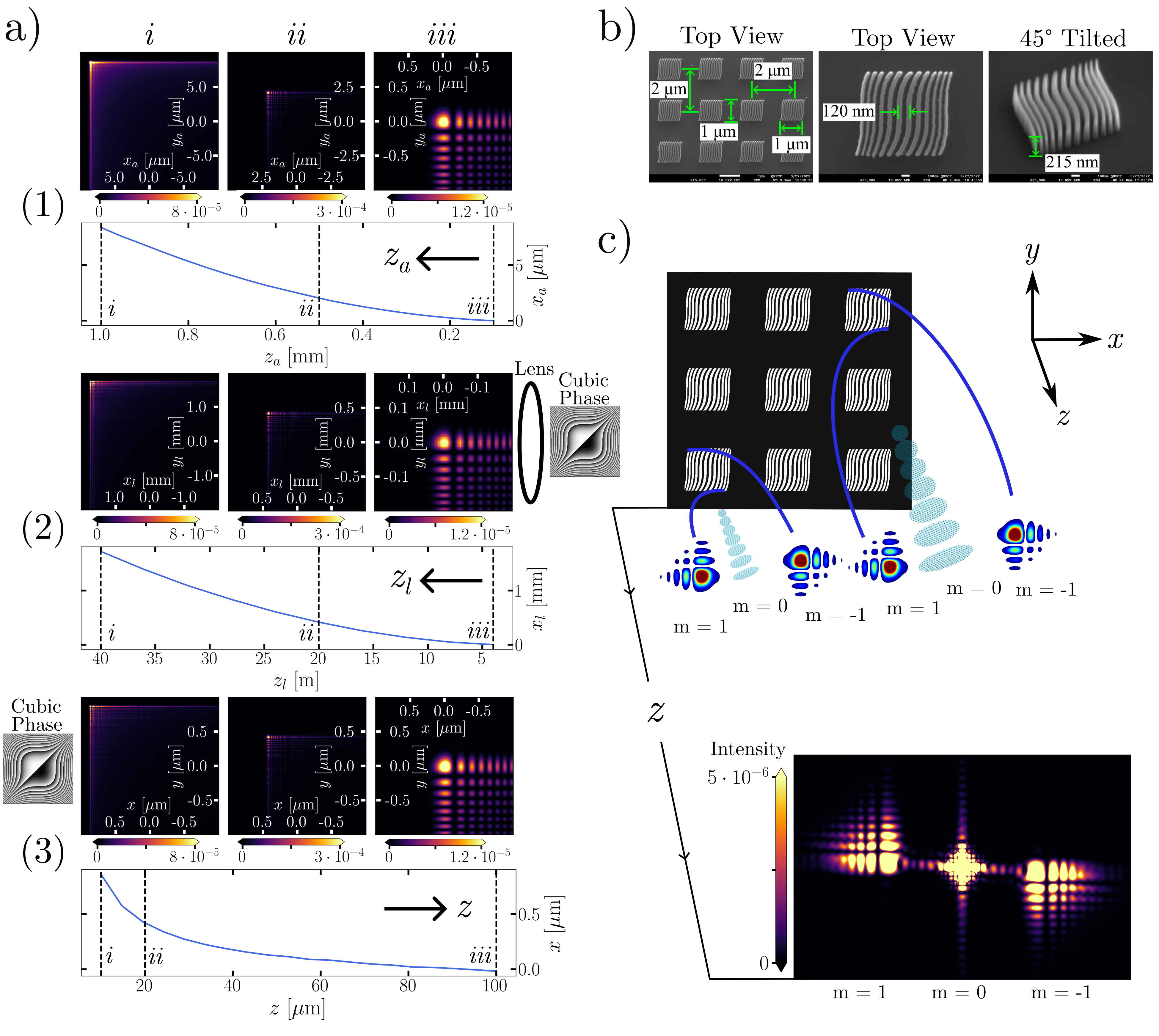
The intensity profiles shown in case (1) of Fig. 1a correspond to propagating the wavefunction a distance of mm, mm, and mm, for Å, m and m. At mm, the Airy beam has shifted in the transverse plane according to Eq. 2 and at mm, the characteristic structure of the Airy beam is just beginning to degrade due to the Gaussian truncation.
In practice, Airy beams can be generated experimentally by imprinting a cubic phase , where typically , on a Gaussian wave packet described by transverse coherence length and then performing an optical Fourier transform by using a lens Siviloglou and Christodoulides (2007); Siviloglou et al. (2007). The propagation dynamics of the Airy beam after the focal spot are scaled relative to the case (1) described above, depending on focal length and the implicit relationship between and :
| (5) |
where is the intensity after the focal spot as shown in Fig. 1a case (2), is given by Eq. 4, and . It follows that Eq. 2 also gets scaled:
| (6) |
With m, mm, and m in Fig. 1a case (2), we obtain parabolic deviation of a few mm over tens of meters, corresponding to an acceleration of about m/s2.
Here we require an alternative approach for generating Airy beams in order to circumvent the challenges associated with neutron beams. Our approach is to imprint a cubic phase on a Gaussian wave packet and let the beam freely propagate without employing a lens. According to the Fraunhofer approximation, the wavefunction in the far field is well approximated by the Fourier transform of the cubic phase profile. We therefore achieve the Airy wavefunction in the far field with an inverse relationship in the propagation dynamics compared to the Airy beam generation with a lens, as shown in Fig. 1a case (3). The intensity profile after the cubic phase mask is given by:
| (7) |
Applying this transformation to Eq. 2, we see that the typical parabolic trajectory associated with Airy beam propagation is mapped to an inverse relationship:
| (8) |
This approach is well-suited for neutrons as it circumvents the fact that the neutron index of refraction in common materials differs from the vacuum by order only , making neutron lens fabrication currently impractical.
III Materials and Methods
An array of binary diffraction phase gratings was fabricated on a silicon wafer where each individual grating profile is given by:
| (9) |
where is the carrier frequency and are cubic coefficients of the grating. The array covered a 0.5 cm by 0.5 cm area and consisted of individual 1 m by 1 m phase gratings, where each one possessed a period nm, height nm, m-3, m-3, and was separated by 1 m on each side from the other phase gratings, as shown in Fig. 1b. The fabrication procedure is identical to the fork-dislocation phase grating procedure outlined in the Supplementary Material of Ref. Sarenac et al. (2022).
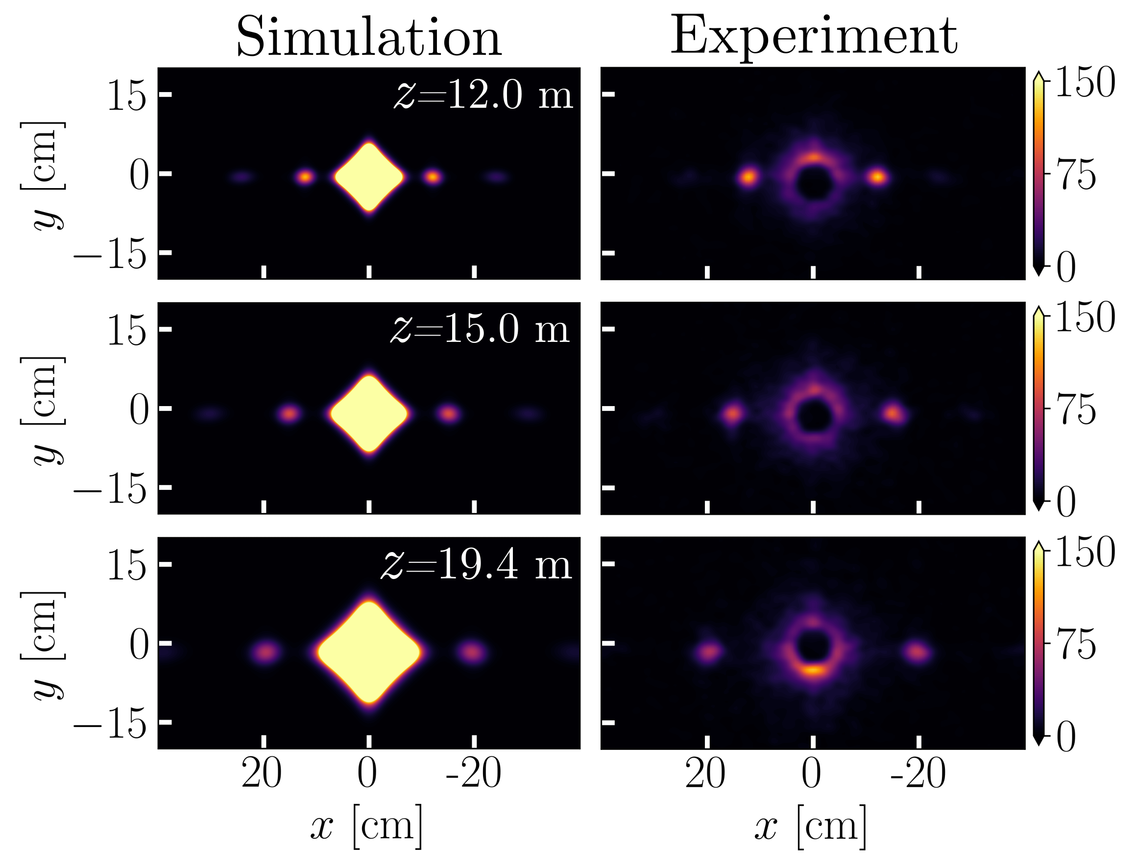
A preliminary study was done at the SANS-I beamline at the Paul Scherrer Institute Kohlbrecher and Wagner (2000), as a result of which an improved setup was devised and implemented at the GP-SANS beamline at the High Flux Isotope Reactor at Oak Ridge National Laboratory Wignall et al. (2012). The silicon wafer was placed inside a mount 17.8 m away from a 20 mm diameter source aperture. Directly in front of the sample was a 4 mm diameter sample aperture. We varied the distance from the sample to the detector from m to m. At each distance, we took measurements with the cubic phase grating array (schematic in Fig. 1c), as well as a linear phase grating array where in Eq. 9 (see the Supplementary Material of Ref. Sarenac et al. (2022) for the SEM profiles of the linear phase gratings). The detector spans an area of m2 with each pixel being mm by mm in size. The wavelength distribution was triangular with , where is the FWHM and the central wavelength is Å. The final SANS data was passed though a low-pass filter to remove the Poissonian noise that varies from pixel to pixel.
IV Results
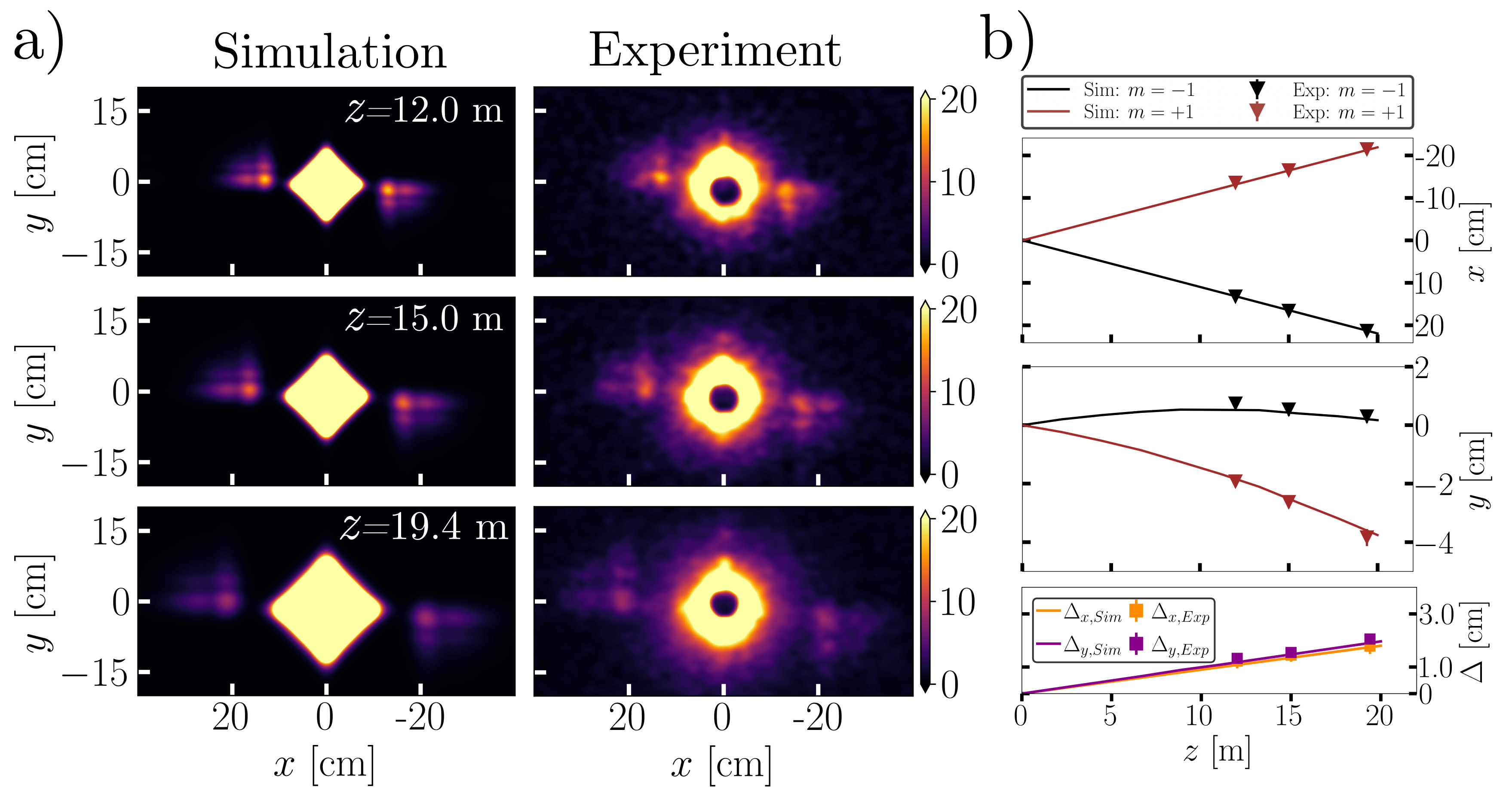
The experiment consisted of measuring far field intensity from an array of cubic and linear phase gratings at grating to camera distances of: m, m and m. Fig. 2a shows the observed Airy beams at different distances (see Appendix for linear phase grating reference measurements). For the simulated profiles, we apply the cubic phase array, with each individual grating profile given by Eq. 9, to a neutron wave packet with transverse coherence length of m at the grating and propagate to the far field, as discussed in detail in section II. We include all of the experimental parameters in the simulation such as wavelength distribution, phase grating array structure, gravity, etc., and in addition account for the experimental resolution by applying a low-pass filter. To account for experimental effects that cause smearing of the intensity pattern, such as vibrations, temperature fluctuations, array size, and pixel size, we convolve the simulated images at each detector position with a Gaussian described by cm m, where m cm is obtained by minimizing the difference between the experimental linear diffraction spot size and the simulation at m.
In Fig. 2b we compute the maximum intensity coordinates of the main Airy lobe and linear diffraction spots for to observe the propagation dynamics and find good agreement with simulations. In the direction, Airy maximum intensity coordinates follow a parabolic trajectory due to the gravitational force; in the direction, they linearly separate in this far field regime.
To further examine Airy propagation dynamics, we can determine the - and -displacement of the maximum intensity position of the Airy beam relative to the propagation center of the first diffraction order :
| (10) |
whereby the displacement is calculated by considering the separation distances between the and diffraction orders for both the Airy and linear case respectively:
| (11) |
| (12) |
As shown in Fig. 2b, we observe linear separation between the curves in both (orange curve) and (purple curve) transverse coordinates, which is in good agreement with theory.
V Conclusion and Discussion
We have introduced and experimentally demonstrated the generation and detection of neutron Airy beams. A holographic approach was used to imprint a cubic phase profile on the neutron wavefunction and observe the Airy beam formation in the far field. We compared Airy beam propagation dynamics with linear diffraction in this far field regime and found excellent agreement with simulations. This work paves the way for further exploration of fundamental properties of Airy beams with neutrons; for example, neutrons are well-suited to study the self-healing properties of Airy beams in scattering experiments, as was done with light in a sample of mono-disperse silica microspheres Broky et al. (2008), since samples of dilute hard spheres are commonly used in neutron imaging and grating interferometer experiments Andersson et al. (2008); Lynch et al. (2011); Sarenac et al. (2024).
Several exciting applications stem from this work; for example, there is recent interest in Airy-vortex beams, whereby a helical wave carrying Orbital Angular Momentum (OAM) is superimposed with an Airy beam Mazilu et al. (2009); Dai et al. (2010, 2011); Karlovets (2015), and the unique interaction of these beams with chiral media Zhuang et al. (2012); Liu and Zhao (2014). Using techniques from Refs. Sarenac et al. (2022, ), neutron Airy-vortex beams could be used to study the scattering properties of Skyrmion samples Henderson et al. (2021, 2022, 2023). Moreover, the coherent superposition of counterpropagating Airy beams has been shown to be abruptly autofocusing along the propagation axis, increasing intensity by orders of magnitude, and then exhibiting Young-type interference fringes with further propagation Efremidis and Christodoulides (2010); Papazoglou et al. (2011); Ángel S. Sanz (2022). This is attractive for neutron experiments where the common optical element, a lens, is impractical and thus abruptly autofocusing neutron Airy beams could be used to improve contrast in neutron imaging, for example. Lastly, this work could also be useful for the experimental investigation of accelerating wave packets accumulating a geometric phase (Berry- or Aharonov-Bohm-like) in a system with no potential whatsoever Kaminer et al. (2015); Allman et al. (1993).
Acknowledgements
This work was supported by the Canadian Excellence Research Chairs (CERC) program, the Natural Sciences and Engineering Research Council of Canada (NSERC), the Canada First Research Excellence Fund (CFREF), and the US Department of Energy, Office of Nuclear Physics, under Interagency Agreement 89243019SSC000025. This work was also supported by the DOE Office of Science, Office of Basic Energy Sciences, in the program ”Quantum Horizons: QIS Research and Innovation for Nuclear Science” through grant DE-SC0023695. A portion of this research used resources at the High Flux Isotope Reactor, a DOE Office of Science User Facility operated by the Oak Ridge National Laboratory. This work is based partly on experiments performed at the Swiss spallation neutron source SINQ, Paul Scherrer Institute, Villigen, Switzerland.
References
- Berry and Balazs (1979) M. V. Berry and N. L. Balazs, “Nonspreading wave packets,” American Journal of Physics (1979).
- Greenberger (1980) Daniel M. Greenberger, “Comment on ”Nonspreading wave packets”,” American Journal of Physics 48, 256–256 (1980).
- Greenberger and Overhauser (1979) Daniel M. Greenberger and A. W. Overhauser, “Coherence effects in neutron diffraction and gravity experiments,” Rev. Mod. Phys. 51, 43–78 (1979).
- Gibbs (1975) R. L. Gibbs, “The quantum bouncer,” American Journal of Physics 43, 25–28 (1975).
- Nesvizhevsky et al. (2000) V.V Nesvizhevsky, H Börner, A.M Gagarski, G.A Petrov, A.K Petukhov, H Abele, S Bäßler, T Stöferle, and S.M Soloviev, “Search for quantum states of the neutron in a gravitational field: gravitational levels,” Nuclear Instruments and Methods in Physics Research Section A: Accelerators, Spectrometers, Detectors and Associated Equipment 440, 754–759 (2000).
- Nesvizhevsky et al. (2002) Valery V. Nesvizhevsky, Hans G. Börner, Alexander K. Petukhov, Hartmut Abele, Stefan Baeßler, Frank J. Rueß, Thilo Stöferle, Alexander Westphal, Alexei M. Gagarski, Guennady A. Petrov, and Alexander V. Strelkov, “Quantum states of neutrons in the earth’s gravitational field,” Nature 415, 297–299 (2002).
- Abele et al. (2009) H. Abele, T. Jenke, D. Stadler, and P. Geltenbort, “Qubounce: the dynamics of ultra-cold neutrons falling in the gravity potential of the earth,” Nuclear Physics A 827, 593c–595c (2009).
- Colella et al. (1975) Roberto Colella, Albert W Overhauser, and Samuel A Werner, “Observation of gravitationally induced quantum interference,” Physical Review Letters 34, 1472 (1975).
- Rubinsztein-Dunlop et al. (2016) Halina Rubinsztein-Dunlop, Andrew Forbes, MV Berry, MR Dennis, David L Andrews, Masud Mansuripur, Cornelia Denz, Christina Alpmann, Peter Banzer, Thomas Bauer, et al., “Roadmap on structured light,” Journal of Optics 19, 013001 (2016).
- Bliokh et al. (2023) Konstantin Y Bliokh, Ebrahim Karimi, Miles J Padgett, Miguel A Alonso, Mark R Dennis, Angela Dudley, Andrew Forbes, Sina Zahedpour, Scott W Hancock, Howard M Milchberg, et al., “Roadmap on structured waves,” Journal of Optics 25, 103001 (2023).
- Siviloglou et al. (2007) G. A. Siviloglou, J. Broky, A. Dogariu, and D. N. Christodoulides, “Observation of accelerating airy beams,” Phys. Rev. Lett. 99, 213901 (2007).
- Siviloglou and Christodoulides (2007) Georgios A. Siviloglou and Demetrios N. Christodoulides, “Accelerating finite energy airy beams,” Opt. Lett. 32, 979–981 (2007).
- Broky et al. (2008) John Broky, Georgios A. Siviloglou, Aristide Dogariu, and Demetrios N. Christodoulides, “Self-healing properties of optical airy beams,” Opt. Express 16, 12880–12891 (2008).
- Efremidis et al. (2019) Nikolaos K. Efremidis, Zhigang Chen, Mordechai Segev, and Demetrios N. Christodoulides, “Airy beams and accelerating waves: an overview of recent advances,” Optica 6, 686–701 (2019).
- Vettenburg et al. (2014) Tom Vettenburg, Heather I C Dalgarno, Jonathan Nylk, Clara Coll-Lladó, David E K Ferrier, Tomáš Čižmár, Frank J Gunn-Moore, and Kishan Dholakia, “Light-sheet microscopy using an airy beam,” Nature Methods 11, 541–544 (2014).
- Jia et al. (2014) Shu Jia, Joshua C. Vaughan, and Xiaowei Zhuang, “Isotropic three-dimensional super-resolution imaging with a self-bending point spread function,” Nature Photonics 8, 302–306 (2014).
- Nylk et al. (2018) Jonathan Nylk, Kaley McCluskey, Miguel A. Preciado, Michael Mazilu, Zhengyi Yang, Frank J. Gunn-Moore, Sanya Aggarwal, Javier A. Tello, David E. K. Ferrier, and Kishan Dholakia, “Light-sheet microscopy with attenuation-compensated propagation-invariant beams,” Science Advances 4, eaar4817 (2018).
- Polynkin et al. (2009) Pavel Polynkin, Miroslav Kolesik, Jerome V. Moloney, Georgios A. Siviloglou, and Demetrios N. Christodoulides, “Curved plasma channel generation using ultraintense airy beams,” Science 324, 229–232 (2009).
- Grier (2003) David G. Grier, “A revolution in optical manipulation,” Nature 424, 810–816 (2003).
- Baumgartl et al. (2008) Jörg Baumgartl, Michael Mazilu, and Kishan Dholakia, “Optically mediated particle clearing using airy wavepackets,” Nature Photonics 2, 675–678 (2008).
- Schley et al. (2014) Ran Schley, Ido Kaminer, Elad Greenfield, Rivka Bekenstein, Yaakov Lumer, and Mordechai Segev, “Loss-proof self-accelerating beams and their use in non-paraxial manipulation of particles’trajectories,” Nature Communications 5, 5189 (2014).
- Clerici et al. (2015) Matteo Clerici, Yi Hu, Philippe Lassonde, Carles Milián, Arnaud Couairon, Demetrios N. Christodoulides, Zhigang Chen, Luca Razzari, François Vidal, François Légaré, Daniele Faccio, and Roberto Morandotti, “Laser-assisted guiding of electric discharges around objects,” Science Advances 1, e1400111 (2015).
- Voloch-Bloch et al. (2013) Noa Voloch-Bloch, Yossi Lereah, Yigal Lilach, Avraham Gover, and Ady Arie, “Generation of electron airy beams,” Nature 494, 331–335 (2013).
- Olver et al. (2010) F. W. J. Olver, D. W. Lozier, R. F. Boisvert, and C. W. Clark, eds., NIST Handbook of Mathematical Functions (Cambridge University Press, New York, NY, 2010).
- Ángel S. Sanz and Martínez-Herrero (2024) Ángel S. Sanz and Rosario Martínez-Herrero, “Exploring the dynamics of finite-energy airy beams: a trajectory analysis perspective,” Opt. Express 32, 5592–5606 (2024).
- Sarenac et al. (2022) Dusan Sarenac, Melissa E Henderson, Huseyin Ekinci, Charles W Clark, David G Cory, Lisa DeBeer-Schmitt, Michael G Huber, Connor Kapahi, and Dmitry A Pushin, “Experimental realization of neutron helical waves,” Science Advances 8, eadd2002 (2022).
- Kohlbrecher and Wagner (2000) Joachim Kohlbrecher and Werner Wagner, “The new sans instrument at the swiss spallation source sinq,” Journal of applied crystallography 33, 804–806 (2000).
- Wignall et al. (2012) George D Wignall, Kenneth C Littrell, William T Heller, Yuri B Melnichenko, Kathy M Bailey, Gary W Lynn, Dean A Myles, Volker S Urban, Michelle V Buchanan, Douglas L Selby, et al., “The 40 m general purpose small-angle neutron scattering instrument at oak ridge national laboratory,” Journal of Applied Crystallography 45, 990–998 (2012).
- Andersson et al. (2008) Robert Andersson, Léon F Van Heijkamp, Ignatz M De Schepper, and Wim G Bouwman, “Analysis of spin-echo small-angle neutron scattering measurements,” Journal of Applied Crystallography 41, 868–885 (2008).
- Lynch et al. (2011) Susanna K. Lynch, Vinay Pai, Julie Auxier, Ashley F. Stein, Eric E. Bennett, Camille K. Kemble, Xianghui Xiao, Wah-Keat Lee, Nicole Y. Morgan, and Han Harold Wen, “Interpretation of dark-field contrast and particle-size selectivity in grating interferometers,” Appl. Opt. 50, 4310–4319 (2011).
- Sarenac et al. (2024) D. Sarenac, G. Gorbet, C. Kapahi, Charles W. Clark, D. G. Cory, H. Ekinci, D. V. Garrad, M. E. Henderson, M. G. Huber, D. Hussey, P. A. Kienzle, J. D. Parker, R. Serrat, T. Shinohara, F. Song, and D. A. Pushin, “Cone beam neutron interferometry: From modeling to applications,” Phys. Rev. Res. 6, 023260 (2024).
- Mazilu et al. (2009) Michael Mazilu, Joerg Baumgartl, Tomas Čižmár, and Kishan Dholakia, “Accelerating vortices in Airy beams,” in Laser Beam Shaping X, Vol. 7430, edited by Andrew Forbes and Todd E. Lizotte, International Society for Optics and Photonics (SPIE, 2009) p. 74300C.
- Dai et al. (2010) H. T. Dai, Y. J. Liu, D. Luo, and X. W. Sun, “Propagation dynamics of an optical vortex imposed on an airy beam,” Opt. Lett. 35, 4075–4077 (2010).
- Dai et al. (2011) H. T. Dai, Y. J. Liu, D. Luo, and X. W. Sun, “Propagation properties of an optical vortex carried by an airy beam: experimental implementation,” Opt. Lett. 36, 1617–1619 (2011).
- Karlovets (2015) Dmitry V. Karlovets, “Gaussian and airy wave packets of massive particles with orbital angular momentum,” Phys. Rev. A 91, 013847 (2015).
- Zhuang et al. (2012) Fei Zhuang, Xinyue Du, Yuqian Ye, and Daomu Zhao, “Evolution of airy beams in a chiral medium,” Opt. Lett. 37, 1871–1873 (2012).
- Liu and Zhao (2014) Xiayin Liu and Daomu Zhao, “Propagation of a vortex airy beam in chiral medium,” Optics Communications 321, 6–10 (2014).
- (38) Dusan Sarenac, Melissa E. Henderson, Huseyin Ekinci, Charles W. Clark, David G. Cory, Lisa DeBeer-Schmitt, Michael G. Huber, Owen Lailey, Jonathan S. White, Kirill Zhernenkov, and Dmitry A. Pushin, “Small-angle scattering interferometry with neutron orbital angular momentum states,” arXiv:2404.00705 .
- Henderson et al. (2021) Melissa E Henderson, James Beare, Sudarshan Sharma, Markus Bleuel, Pat Clancy, David G Cory, Michael G Huber, Casey A Marjerrison, Mathew Pula, Dusan Sarenac, et al., “Characterization of a disordered above room temperature skyrmion material co8zn8mn4,” Materials 14, 4689 (2021).
- Henderson et al. (2022) ME Henderson, M Bleuel, J Beare, DG Cory, B Heacock, MG Huber, GM Luke, M Pula, D Sarenac, S Sharma, et al., “Skyrmion alignment and pinning effects in the disordered multiphase skyrmion material co 8 zn 8 mn 4,” Physical Review B 106, 094435 (2022).
- Henderson et al. (2023) ME Henderson, B Heacock, M Bleuel, DG Cory, C Heikes, MG Huber, J Krzywon, O Nahman-Levesqué, GM Luke, M Pula, et al., “Three-dimensional neutron far-field tomography of a bulk skyrmion lattice,” Nature Physics 19, 1617–1623 (2023).
- Efremidis and Christodoulides (2010) Nikolaos K. Efremidis and Demetrios N. Christodoulides, “Abruptly autofocusing waves,” Opt. Lett. 35, 4045–4047 (2010).
- Papazoglou et al. (2011) Dimitrios G. Papazoglou, Nikolaos K. Efremidis, Demetrios N. Christodoulides, and Stelios Tzortzakis, “Observation of abruptly autofocusing waves,” Opt. Lett. 36, 1842–1844 (2011).
- Ángel S. Sanz (2022) Ángel S. Sanz, “Flux trajectory analysis of airy-type beams,” J. Opt. Soc. Am. A 39, C79–C85 (2022).
- Kaminer et al. (2015) Ido Kaminer, Jonathan Nemirovsky, Mikael Rechtsman, Rivka Bekenstein, and Mordechai Segev, “Self-accelerating dirac particles and prolonging the lifetime of relativistic fermions,” Nature Physics 11, 261–267 (2015).
- Allman et al. (1993) B. E. Allman, A. Cimmino, A. G. Klein, G. I. Opat, H. Kaiser, and S. A. Werner, “Observation of the scalar aharonov-bohm effect by neutron interferometry,” Phys. Rev. A 48, 1799–1807 (1993).
Appendix
The measurement of far field neutron intensity after an array of linear phase gratings is used as a reference point to determine neutron Airy beam propagation dynamics. Shown in Fig. 3 are the measured linear phase grating benchmark measurements at grating to camera distances of: m, m and m. We find good agreement with simulation and compare the linear and Airy beam propagation dynamics in section IV and Fig. 2b.