Fluid Antennas-Enabled Multiuser Uplink: A Low-Complexity Gradient Descent for Total Transmit Power Minimization
Abstract
We investigate multiuser uplink communications from multiple single-antenna users to a base station (BS), which is equipped with multiple fluid antennas (FAs) and adopts zero-forcing receivers to decode multiple signals. We aim to optimize antennas’ positions at the BS, to minimize the total transmit power of all users subject to the minimum rate requirement. After applying transformations, we show that the problem is equivalent to minimizing the sum of each eigenvalue’s reciprocal of a matrix, which is a function of all antennas’ positions at the BS. Subsequently, the projected gradient descent (PGD) method is utilized to find a locally optimal solution. In particular, different from the latest related work, we exploit the eigenvalue decomposition to successfully derive a closed-form gradient for the PGD, which facilitates the practical implementation greatly. We demonstrate by simulations that via careful optimization for all antennas’ positions in our proposed design, the total transmit power of all users can be decreased significantly as compared to competitive benchmarks.
Index Terms:
Fluid antennas, multiuser uplink, total transmit power minimization, projected gradient descent.I Introduction
Beamforming, which exploits the degree of freedom (DoF) in the spatial domain, is a powerful technique for improving system capacity [1]. In conventional beamforming, positions of antennas at transceivers are fixed which may limit the gains of beamforming depending on channel conditions.
To mitigate the above deficiency, the intelligent reflecting surface (IRS) technique has been proposed and proven to be capable of reconfiguring wireless channels by adjusting passive IRS reflecting coefficients [2]. As another promising technology, fluid antennas (FAs) [3][6] has emerged recently. Although its operating principle is different from that of the IRS, FAs can also reshape channel environments artificially, by adaptively adjusting positions of all antennas (connected to the radio frequency chains via flexible cables) supported by the stepper motors or servos. Unlike antenna selection (AS) which requires more candidate antennas, higher hardware cost and larger overhead of channel estimation, and concurrently unlike rotatable uniform linear array (RULA) which just mechanically rotates the transmit/receive array and cannot fully exploit spatial channel variation, FAs fully exploites the channel variation resulting from changes in antennas’ positions to achieve a higher spatial diversity without causing additional hardware or algorithm cost [7]. Driven by these potential advantages, earlier works have applied the technology of FAs to further enhance capacities of multiple-input multiple-output (MIMO) systems [7][8], multiuser uplink/downlink communications [9][10], physical-layer security systems [11] or interference networks [12].

In this letter, as in [9], we focus on FAs-enabled classical multiuser uplink communications. Specifically, we assume multiple single-antenna users that intend to concurrently transmit their signals to a base station (BS), which is equipped with FAs and adopts the widely used zero-forcing (ZF) receivers to detect multiple signals. By carefully optimizing positions of all antennas at the BS, our goal is to minimize the total transmit power of all users subject to the minimum rate requirement for each user. The formulated problem is highly non-convex, and we develop a projected gradient descent (PGD) method to find a locally optimal solution. Unlike [9] which exploits the original definition-based method to compute the gradient in each iteration, the key contribution of this letter is that we successfully derive a closed-form gradient in each iteration with the help of the eigenvalue decomposition. This novelty greatly accelerates the implementation of the PGD method. Numerical results are performed to demonstrate that our proposed method with FAs can significantly decrease the total transmit power of all users as compared to competitive benchmarks.
II System Model and Problem Formulation
As shown in Fig. 1, we consider multiuser uplink communications from single-antenna users to the BS equipped with FAs distributed along a linear dimension, with . Consider the line-of-sight (LoS) propagation environment, the channel vector between the BS and is denoted by111As shown in the follows, the simple LoS environment is considered here since we aim to demonstrate that our proposed design of FAs’ movements just relies on the slow-changing property of statistical channel state information (CSI). In the simulations, we will show the effectiveness of the proposed FAs’ movement rule when facing random Rician fading channels.
| (1) |
where is the signal wavelength, is the angle of arrival (AoA) to the BS at , and denotes the adjustable position of the -th antenna at the BS, with . For the multiuser uplink, the received signals at the BS can be expressed as
| (2) |
where , , in which denotes the transmit power of , , in which denotes the transmitted signal of and . In addition, is the receive combining matrix at the BS, in which is the combining vector for the signal , and , in which is the additive white Gaussian noise at the -th BS antenna, with . Based on (2), the received signal-to-interference-plus-noise ratio (SINR) of the signal at the BS is derived as
| (3) |
In this letter, we assume that the BS adopts the widely used linear ZF detector for processing multiple signals, due to its low implementation complexity especially when number of antennas at the BS is large. Based on this, the receive combining matrix is accordingly expressed as
| (4) |
Substituting (4) into (3), the received SINR of the signal is given by
| (5) |
Our goal is to optimize the positions of FAs at the BS, i.e., , to minimize the total transmit power of users subject to a minimum achievable rate requirement for each user. Hence, the optimization problem is formulated as222In this work, only antennas’ positions are optimized for total power minimization. Consider the case where receiving beamforming and antennas’ positions are jointly optimized, the generalized Bender’s decomposition [13] can be exploited for obtaining the globally optimal solution.
| () | |||
| () | |||
| () |
where in the constraint (6b) denotes the minimum rate requirement for , and in (6c) denotes the feasible moving region for antennas at the BS. More specifically, denote the total span for the movement of FAs as and without loss of generality set . Then, consider: i) the minimum distance between any two FAs to avoid the coupling effect as [7], [8], i.e., , ; ii) the movement span should be the same for each antenna, we can conveniently set , where
from which we have and , . The feasible movement region for each FA is illustrated in Fig. 2 for better understanding.

| (13) |
| (18) |
Based on (6b), it can be shown that should satisfy
| (7) |
where . According to (7), we can equivalently replace the objective of (P1) as [9]
| (8) |
where and denotes the -th eigenvalue of the matrix . Therefore, problem (P1) can be equivalently reformulated as
| () | |||
| () |
Remark 1: Problem (P2) is highly non-convex because its objective is neither convex or concave, which cannot be solved via standard convex optimization techniques. Motivated by this, the authors in [9] try to solve (P2) by resorting to the PGD method, which handles the simple unconstrained or constrained problems well and is not sensitive to concavity or convexity of the objective. However, [9] computes the gradient based on the original definition shown in its equation (12), which has the large implementation complexity. In the next section, we show how to reduce the complexity significantly.
Remark 2: Considering the LoS environment, the BS can easily estimate the CSI by just estimating the AoAs to itself at users based on some mature algorithms, such as MUSIC. Based on this, the BS can directly optimize FAs’ positions via the proposed algorithm and then feedback each user the required transmit power based on (7) with optimized .333In addition, even the general Rician fading is considered, the BS still optimizes FAs’ positions in advance based on the estimated AoAs. Then, in the communication process, all antennas’ positions are not changed and each user sends pilot signals to the BS for uplink channel estimations. When the BS successfully estimates the instantaneous CSI, it can tell each user the required transmit power based on (7). Since no antennas’ movements are involved, the consumed time for estimate-feedback is much smaller than the channel coherence time (CCT), especially for the low-mobility scenario where CCT is relatively larger [14].
III Algorithm Design for Solving (P2)
In this letter, we still exploit the PGD method to find a locally optimal solution to (P2). Specifically, using PGD, the update rule for in the -th iteration is given by
| (10) |
where in the first equation is the original updated , and in the second equation is the additional update (if necessary) via the projection function as explained later, which ensures that the solutions for FAs’ positions in each iteration always satisfy the constraint in (9b). Further, denotes the gradient of at , and is the step size for the gradient descent.
A. Computing : Note that . Using the chain rule, , , can be derived as
| (11) |
Based on (11), to compute , the key is to derive a closed-form expression for , and .
To proceed, let us denote as the eigenvalue decomposition of the matrix , where consists of linearly independent columns with unit norm, and . Then, we can equivalently express as
| (12) |
Based on (12), can be expanded as in (13), where is established since and . Then, further note that the sum of the first and third terms in (13) equals
| (14) |
where is established since always equals the constant one and thus is not relevant to in any situation. Based on (13) and (14), can be simplified as
| (15) |
where is established since is a real number. Recall that and . The element in the -th row and -th column of based on (1) can be derived as
| (16) |
based on which it is easy to derive the element in the -th row and -th column of as
| (17) |
Finally, by substituting the known into (15) and then substituting (15) into (11), the gradient at can be computed as in (18).
B. Determining the feasible step size: In the PGD method, a correct setting for the step size in each iteration is important for realizing convergence. Specifically, the feasible in each iteration should satisfy , where is a Lipschitz constant for , which satisfies , [15]. Since the structure of is much complex, generally is difficult to determine. Based on this fact, we can instead exploit the backtracking line search (BLS) [16] to find a feasible . The details are shown in Algorithm 1, where denotes the shrinking factor.
C. Determining the projection function : Recall that the projection function mainly ensures that FAs only move in their respective feasible regions. Therefore, according to the rule of nearest distance, can be determined as
| (19) |
D. The algorithm, complexity analysis and comparison: The overall setups for solving problem (P2) are summarized in Algorithm 2, where denotes the prescribed accuracy. Generally, the PGD based minimization may lead to sightly different total transmit power for different initialization and step-sizes . This is mainly because the PGD may converge to a local minimum of the objective, which is an unavoidable phenomenon arising in non-convex optimization problems. Nevertheless, this phenomenon can be well solved by randomly generating numerous different and then selecting the one which produces the minimum power.
Complexity Analysis: To simplify the analysis while still capturing the complexity of Algorithm 2, we here focus on the number of complex multiplications required in each iteration. Specifically, the complexity of the eigenvalue decomposition for is about [9]. Further, calculating , , requires complex multiplications, leading to the complexity of computing as . In addition, the complexity of finding a feasible is about , where is the complexity of computing in step 3 of Algorithm 1, and is the maximum number of iterations for BLS. Hence, the total complexity of Algorithm 2 is about
where is the maximum number of iterations for repeatedly implementing steps 3-5 in Algorithm 2.
Complexity Comparison: As a comparison, if the original definition based method [9] is exploited to compute the gradient, i.e.,
| (20) |
the corresponding complexity will become larger. Specifically, given and , using the eigenvalue decomposition to obtain for all requires a complexity of . Similarly, the complexity of obtaining is . Therefore, the complexity of obtaining is about , and then the total complexity of Algorithm 2 becomes
which is clearly higher than the complexity of Algorithm 2 in this work, especially when is large. We compare the above two complexities versus in Fig. 3 for better illustration, where we set and .


(a)
(b)

(c)
IV Simulation Results
In this section, we present numerical results to demonstrate the effectiveness of the proposed design over the general Rician fading, in which the channel vector between the BS and is , where is the Rician factor, is given in (1), and each element of is i.i.d. complex Gaussian distributed with zero mean and unit variance. Under this setup, optimal (denoted as ) is still obtained based on statistical AoAs, while the objective of total transmit power becomes , with . For convincing comparisons, we further consider three widely used benchmarks:
-
•
RPA: The line segment of length is quantized into discrete locations with equal-distance , and out of these locations are optimally selected for antenna positions.
-
•
FPA: Each antenna has a fixed position, i.e., .
-
•
Minimum mean square error (MMSE) combining: The BS will exploit MMSE combining to detect multiple signals, where positions of all antennas are optimized employing the method in [9], but base on statistical AoAs.
For the system parameters, we set the minimum distance between any two adjacent FAs as , and without prejudice to the conclusion, is set to 1 for simplification. We consider users and the AoAs are , and , respectively. In addition, the noise power is set as for normalizing the large-scale channel fading power.
Fig. 4 first illustrates the convergence behavior of our proposed design under the LoS channels and for the case of and , . Corresponding to different , the initial condition for the iteration is set as . As we can observe, the total transmit power of all users rapidly converges to a constant within dozens of iterations. Therefore, the proposed design is computationally efficient which may be suitable for the practical implementation.
Fig. 5(a) compares the total transmit power of four schemes with respect to (w.r.t.) number of transmit antennas at the BS () for the case of , and . We can observe that: i) as increases, the BS can better distinguish signals in different directions and achieve higher reception gains, which in turn allows the users to transmit their signals with less power; ii) compared to FPA and RPA, the proposed design can optimally exploit the additional spatial DoF, so that the resulting total transmit power can be minimized; iii) as increases, the performance gap between RPA and the proposed design decreases. The reason is that when is fixed, each antenna can just move in a smaller region when increases, which implies that there may be not much performance difference from discrete positions selection in RPA or optimal FAs’ movements in the proposed design; iv) as reported in [9], due to the more powerful detection ability, MMSE combining outperforms the proposed design slightly.
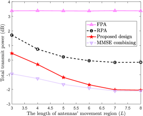
Fig. 5(b) shows the total transmit power w.r.t. the span of FAs’ movement () for the case of , and , from which it is observed that when increases, the total transmit power of RPA, the proposed design and MMSE combining first becomes smaller and then converges to a constant. This phenomenon reveals that it is not necessary to expand indefinitely and only a limited span is enough to achieve the optimal performance.
Finally, Fig. 5(c) shows the total transmit power w.r.t. the Rician factor for the case of , , and , from which it is observed that no matter whether is large (the LoS condition is dominate for each channel between the user and the BS) or small (the random Rayleigh fading is dominate for each channel between the user and the BS), our proposed design with statistical AoAs always achieves pretty good performance compared to FPA and RPA, indicating that our proposed design is not sensitive w.r.t. random fading components in Rician channels.
V Conclusion
This letter considers multiuser uplink communication supported by the FAs-enabled base station, which exploits zero-forcing receivers to decode multiple signals. The objective is to optimize the FAs’ positions at the BS, to minimize the total transmit power of all users subject to the minimum rate requirement. We develop a projected gradient descent method to iteratively find a locally optimal solution, at significantly reduced complexity compared to state of the art since a closed-form gradient is derived successfully. Results show the performance superiority of our proposed design compared to several benchmarks.
References
- [1] W. Xia, et. al., “A deep learning framework for optimization of MISO downlink beamforming,” IEEE Trans. Commun., vol. 68, no. 3, pp. 18661880, March 2020.
- [2] Q. Wu, et. al., “Intelligent reflecting surface enhanced wireless network via joint active and passive beamforming,” IEEE Trans. Wireless Commun., vol. 18, no. 11, pp. 53945409, Nov. 2019.
- [3] L. Zhu, et. al., “Movable antennas for wireless communication: Opportunities and challenges,” IEEE Commun. Mag., early access. DOI: 10.1109/MCOM.001.2300212.
- [4] W. K. New, et. al., “Fluid antenna system: New insights on outage probability and diversity gain,” IEEE Trans. Wireless Commun., early access. DOI: 10.1109/TWC.2023.3276245.
- [5] K. K. Wong, et. al., “Fluid antenna systems,” IEEE Trans. Wireless Commun., vol. 20, No. 3, pp. 19501962, March 2021.
- [6] K. K. Wong, et. al., “Fluid antenna multiple access,” IEEE Trans. Wireless Commun., vol. 21, No. 7, pp. 48014815, July 2022.
- [7] W. Ma, et. al., “MIMO capacity characterization for movable antenna systems,” IEEE Trans. Wireless Commun., early access. DOI: 10.1109/TWC.2023.3307696.
- [8] Y. Ye, et. al., “Fluid antenna-assisted MIMO transmission exploiting statistical CSI,” IEEE Commun. Lett., early access. DOI: 10.1109/LCOMM.2023.3336805.
- [9] L. Zhu, et. al., “Movable-antenna enhanced multiuser communication via antenna position optimization,” arXiv: 2302.06978, 2023.
- [10] Z. Xiao, et. al., “Multiuser communications with movable-antenna base station: Joint antenna positioning, receive combining, and power control,” arXiv: 2308.09512, 2023.
- [11] G. Hu, et. al., “Secure wireless communication via movable-antenna array,” arXiv: 2311.07104, 2023.
- [12] L. Zhu, et. al., “Movable-antenna array enhanced beamforming: Achieving full array gain with null steering,” IEEE Commun. Lett., early access. DOI: 10.1109/LCOMM.2023.3323656.
- [13] Y. Wu, et. al., “Movable antenna-enhanced multiuser communication: Optimal discrete antenna positioning and beamforming,” arXiv: 2308.02304, 2023.
- [14] T. Van Chien, et. al., “Uplink power control in massive MIMO with double scattering channels,” IEEE Trans. Wireless Commun., vol. 21, no. 3, pp. 19892005, March 2022.
- [15] A. Beck, et. al., “A fast iterative shrinkage-thresholding algorithm for linear inverse problems,” SIAM J. Imag. Sci., vol. 2, no. 1, pp. 183202, 2009.
- [16] S. Boyd and L. Vandenberghe, Convex Optimization. Cambridge, U.K.: Cambridge Univ. Press, 2004.