Experimental Demonstration of Stationary Dark-State Polaritons Dressed by Dipole-Dipole Interaction
Abstract
Dark-state polaritons (DSPs) based on the effect of electromagnetically induced transparency are bosonic quasiparticles, representing the superpositions of photons and atomic ground-state coherences. It has been proposed that stationary DSPs are governed by the equation of motion closely similar to the Schrödinger equation and can be employed to achieve Bose-Einstein condensation (BEC) with transition temperature orders of magnitude higher than that of the atomic BEC. The stationary-DSP BEC is a three-dimensional system and has a far longer lifetime than the exciton-polariton BEC. In this work, we experimentally demonstrated the stationary DSP dressed by the Rydberg-state dipole-dipole interaction (DDI). The DDI-induced phase shift of the stationary DSP was systematically studied. Notably, the experimental data are consistent with the theoretical predictions. The phase shift can be viewed as a consequence of elastic collisions. In terms of thermalization to achieve BEC, the m2-size interaction cross-section of the DDI can produce a sufficient elastic collision rate for the stationary DSPs. This work makes a substantial advancement toward the realization of the stationary-DSP BEC.
Diluted atomic gases were the first successful physical systems to reach the Bose-Einstein condensation (BEC) by cooling the bosonic atoms below the transition temperatures Wieman1995 ; Ketterle1995 . In such systems, particle-particle interactions are usually weak, or their scattering lengths are typically much less than mean particle spacings—that is the diluteness. The rapid development of optical microcavities makes it possible to realize exciton-polariton BEC in solid-state systems Kasprzak2006 ; BECReview2010 ; PolaritonThermalTime1 ; PolaritonThermalTime2 ; Shishkov2022 . Concerning the uses of Bose condensates, exciton-polariton BECs are limited to two-dimensional systems and have lifetimes comparable to or shorter than thermalization times.
A unique platform of stationary dark-state polaritons (DSPs) to achieve BEC was proposed in Ref. Fleischhauer2008 . Compared with the exciton-polariton BEC system, the stationary-DSP BEC system is three-dimensional and has a much longer lifetime. The DSPs are bosonic particles and represent the superposition of probe photon and atomic coherence. They are formed by the interaction between a weak probe pulse and atoms under the presence of a strong coupling field based on the effect of electromagnetically induced transparency (EIT) as depicted in Fig. 1(a). The EIT mechanism can store the DSPs in the atoms by turning off the coupling field, and later retrieve the DSPs by turning on the coupling field. Furthermore, when the two counter-propagating coupling fields are applied, the DSPs become stationary and diffuse in the forward and backward directions Bajcsy2003 ; Lin2009 ; Chen2012 ; Blatt2016 ; Campbell2017 ; KimSLP2018 ; Everett2019 ; KimYH2022 .
In Ref. Fleischhauer2008 , Fleischhauer et al. showed that the stationary DSPs are governed by the equation of motion closely similar to the Schrödinger equation. They further proposed utilizing a nonlinear Kerr effect to mediate the interaction between the DSPs for thermalization to achieve BEC. However, the proposed Kerr-type interaction is typically too weak to make a sufficient elastic collision rate for thermalization. Therefore, this present work aimed to substitute the dipole-dipole interaction (DDI) between Rydberg-state atoms for the Kerr-type interaction to make the stationary-DSP BEC feasible.
Rydberg atoms possess strong DDI Lukin2001 ; Tong2004 ; Heidemann2007 ; RevModPhys2010 ; Adams2010 , leading to the applications such as quantum logic gates Saffman2005 ; Keating2015 ; Tiarks2019 ; Vaneecloo2022 ; Stolz2022 , single-photon sources Ripka2018 ; Ornelas-Huerta2020 ; Shi2022 , and strongly-correlated many-body physics Pupillo2010 ; Peyronel2012 ; Moos2015 ; Browaeys2020 . In our earlier work, we experimentally demonstrated a many-body system of Rydberg polaritons based on the EIT effect OurCommunPhys2021 , where the Rydberg polariton represents the superposition of the photon and the coherence between a Rydberg and a ground state. Slow light arising from the EIT effect greatly enhances the interaction time between light and matter, which can be a couple of s to about 10 s in a medium of high optical depth (OD) OurCommunPhys2021 ; Chen2012 ; OurPRL2013 ; Our2022 . In the thermalization process, the high-OD medium made the interaction time compatible with the elastic collision rate of the m2-size interaction cross-section due to the DDI between Rydberg polaritons. Hence, we observed a cooling effect in the transverse direction of slowly-propagating Rydberg polaritons OurCommunPhys2021 .
According to Ref. OurCommunPhys2021 , one could create stationary Rydberg polaritons to achieve BEC. The formation of stationary polaritons involves the four-wave mixing (FWM) process Bajcsy2003 ; Lin2009 ; Chen2012 ; Blatt2016 ; Campbell2017 ; KimSLP2018 ; Everett2019 ; KimYH2022 . The ladder-type transition scheme, which typically has a very large phase mismatch in the FWM process, is employed in the Rydberg-EIT system to form the stationary Rydberg polaritons. However, the probe and coupling fields had the typical wavelengths of 780 or 795 nm and around 480 nm in a Rydberg-EIT system, resulting in an FWM phase mismatch of – rad. Such a large phase mismatch completely destroys stationary Rydberg polaritons and makes the search for the Rydberg-polariton BEC impractical.
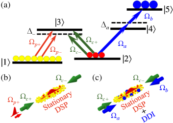
In this study, we proposed and experimentally demonstrated the stationary DSPs possessing the Rydberg-state DDI. In addition to the probe and coupling fields that formed the stationary DSP via the FWM process, two more laser fields were applied to drive the two-photon transition (TPT) of as shown by Fig. 1(a). The TPT generated the Rabi oscillation between the population of the ground state and that of the Rydberg state , as well as between the ground-state coherence and the Rydberg coherence . Due to the existence of the Rydberg population, the DDI resulted in the phase shift and attenuation of the stationary DSP. With regard to the thermalization of stationary DSPs, the DDI can lead to a far larger elastic collision rate than the Kerr-type interaction. Hence, this work makes a substantial advancement toward the realization of the stationary-DSP BEC.
We carried out the experiment in laser-cooled 87Rb atoms with a temperature of about 350 K. Before each measurement, the magnetic and laser fields for the production of the cold atoms were switched off, and we optically pumped all the population to a single Zeeman state. Details of the atom cloud and the experimental procedure before the measurements can be found in Refs. OurPRA2019 ; OurCommunPhys2021 .
All the laser fields had the polarization in the experiment. In the -type EIT system shown by Fig. 1(a), , , and are , , and . The EIT was driven resonantly, while the fields in the forward direction ( and ) had nearly zero one-photon detuning, and those in the backward direction ( and ) had the one-photon detuning of Lin2009 . In the TPT system shown by Fig. 1(a), is and is . We made the TPT resonant at nearly no DDI and set the one-photon detuning to +5 to make excitation to negligible.
The propagation direction of was exactly opposite to that of as depicted in Fig. 1(b). When interacting with the atoms, and propagated in the nearly same direction with an angle separation of about 0.3∘ Lin2009 . The backward probe field , or more precisely , depicted in Fig. 1(a) only appeared during the stationary DSP, and its value was nearly the same as Lin2009 . Driving the transitions of and , the TPT fields with Rabi frequencies of and counterpropagated in the forward and backward directions as depicted in Fig. 1(c). The laser beams of and completely covered the region of stationary DSPs. Other details of the experimental setup can be found in Sec. I of the Supplemental Material (SM).
We made theoretical predictions using the optical Bloch equations of the density-matrix operator and the Maxwell-Schrödinger equations of the probe fields. Details of the equations and calculation can be found in Sec. II of the SM. In our earlier works OurPRR2022 ; OurOEMFT , the predictions are in good agreement with the experimental data.
We set in the experiment, where is the two-photon detuning in the -type EIT system. In Ref. Tebbenv2021 , Tebben et al. theoretically studied a similar transition scheme, except that the TPT is replaced by a one-photon transition. They showed that the optimum , which maximizes the stationary-DSP energy, is equal to a half of the Rabi frequency of the one-photon transition OurIDR . In our TPT case, is the optimum value.
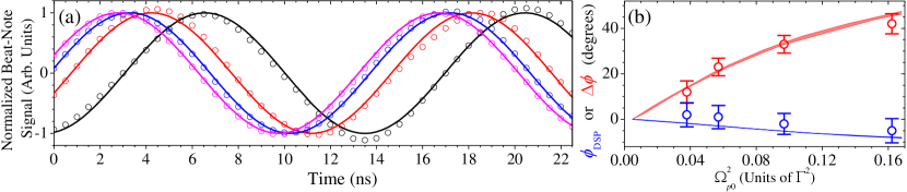
Representative data that demonstrate the formation of stationary DSPs in the -type EIT system are shown by Fig. 2(a) (2(b)) without (with) the TPT. The Rabi oscillation between the population in and that in (or between coherences and ) was clearly observed during the magenta pulse in Fig. 2(b). The consistency between the data and the predictions is satisfactory. More details of the data are described in Sec. III of the SM.
In the measurements of the DSPs without and with the TPT such as Fig. 2, the Rabi frequencies , , and , the optical density or abbreviated as OD (), and the ground-state decoherence rate () were pre-determined OurPRA2019 ; PhotonSwitching ; OurPRL2006 , where the probe transmission without the EIT is indicated by and the decay rate of the coherence is represented by . Details of the determination methods and representative data are presented in Secs. I and IV of the SM. The Rabi frequency was determined by the period of the Rabi oscillation during the TPT. The stationary DSP is generated by the FWM process, in which the phase mismatch causes the energy loss Chen2012 ; Ldk2004 ; FBS2021 . The degree of phase mismatch is given by [see Eq. (S18) in the SM]. We determined the value of by the comparison between the experimental results and theoretical predictions. Details can be found in Sec. V of the SM, which provides more evidence for the formation of stationary DSPs.
We varied the input probe power LargeOmega_p0 , while keeping the pulse width and beam profile the same, and measured the data similar to those in Figs. 2(a) and 2(b). The population in , , is about equal to due to the EIT effect. Thus, a larger input probe intensity, , resulted in larger and , which produced a higher DDI strength OurCommunPhys2021 . We determined the attenuation coefficients, and , as functions of , where and are defined as the logarithm of the ratio of input to output probe energies without and with the DDI, and is the square of the Rabi frequency of the input probe pulse peak. In Fig. 2(c), the blue and red circles represent the data of and (). Since the OD fluctuated about 1 and the ground-state decoherence rate fluctuated about , the predictions of and are plotted as the blue and red areas.
The TPT made the population (coherence) oscillate between and (between and ), and the population in induced the DDI. We characterized the DDI coefficient, , which is defined as the decoherence rate (also frequency shift) per OurOEMFT ; OurCommunPhys2021 ; OurPRR2022 . See also Eqs. (S15) and (S16) in the SM for the definition of . The ratio of retrieved probe energies with to without the TPT was measured against the input probe intensity or equivalently the peak Rabi frequency square, , as shown in Fig. 2(c). We compared the data with the predictions to determine 0.60 and (the decay rate of the coherence ) = 0.020. We also estimated the value of , and details can be found in Sec. VI of the SM. The estimation gives of 0.54, indicating that the experimentally determined of 0.60 is reasonable.
The DDI induces a phase shift of the stationary DSP, and the phase of the retrieved probe pulse is shifted. To further verify the creation of the stationary DSP dressed by the DDI, we applied the TPT and measured the phase shift of the retrieved probe pulse, i.e., the difference of the phases with and without the atoms. The beat-note interferometer was employed to measure the phase evolution around the pulse peak beatnote ; OurCommunPhys2021 . The experimental parameters in the phase measurement are the same as those in the transmission measurement. In Fig. 3(a), the black circles are the beat-note data without the TPT or DDI, which serve as the reference for the other data. The red, blue, and magenta circles represent the data with increasing values of or DDI strength. A larger DDI strength resulted in a larger phase shift as expected.
We measured the phase shifts of the retrieved probe pulses without and with the TPT, and , respectively, as functions of . In Fig. 3(b), the blue and red circles represent and (). We subtracted the measured phase shift at 0.07 from the data. The subtraction removes the phase shift contributed from the Rabi oscillation. Thus, exhibits mainly the DDI effect. More details can be found in Sec. VIII of the SM. Without the DDI, of the stationary DSP depends on the probe intensity a little. Owing to the DDI, depends on the probe intensity significantly. The blue and red areas are the theoretical predictions. In the theoretical calculation, all the parameters are non-adjustable and experimentally pre-determined. The consistency between the data and predictions is satisfactory, confirming that the stationary DSP indeed possessed the DDI.
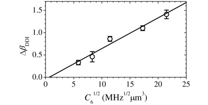
As another evidence of the stationary DSPs carrying the DDI, we measured the DDI effect at different Rydberg states with the principal quantum numbers, , of 28, 30, 32, 35, and 38. The DDI potential energy between two Rydberg atoms is given by , where is van der Waals coefficient and is the distance between the atoms. The DDI energy shift or DDI-induced attenuation coefficient is linearly proportional to OurOEMFT ; SqrtC6-1 ; SqrtC6-2 ; SqrtC6-3 . In Fig. 4, we plot the experimental data of DDI-induced attenuation coefficient, , against , where is the difference between the DDI-induced attenuation coefficient of and that of . This can avoid any attenuation effect that depends on , e.g., different two-photon frequency fluctuations due to different ’s, except the DDI effect. The values of were obtained from the programming code provided by Ref. C6 . The experimental data of clearly exhibit the linear dependence on , further confirming that the stationary DSPs possess the DDI.
We now estimate whether the present experimental condition is close to the observation of stationary-DSP BEC. Details of the estimations can be found in Sec. IX of the SM. Based on the formulas in Ref. Fleischhauer2008 , the BEC transition temperature, , is about 4.0 mK and the stationary-DSP temperature, , is around 3.8 K. The measured phase shift indicates that the elastic collision rate, , is approximately 33 s-1. Under , such enables the thermal equilibrium of stationary DSPs, and makes the BEC feasible. To observe the BEC, we still need to build an artificial trap and produce stationary DSPs in the quasi-continuous mode.
In conclusion, we experimentally demonstrated the formation of the stationary DSP dressed by the DDI, using the scheme of the -type EIT system together with the TPT-driven Rabi oscillation between a ground state and a Rydberg state. The scheme overcomes the severe problem of a large phase mismatch in the direct formation of the stationary Rydberg polariton. As proposed in Ref. Fleischhauer2008 , the system of stationary DSPs is the possible platform for a three-dimensional and long-lifetime Bose condensate. Our work made the stationary DSPs carry the DDI and provided a feasible method of thermalization for the realization of BEC.
ACKNOWLEDGMENTS
This work was supported by Grants No. 110-2639-M-007-001-ASP and No. 111-2639-M-007-001-ASP of the National Science and Technology Council, Taiwan, and Grant No. 111-2923-M-008-004-MY3 of the Mutual Funds for Scientific Cooperation between Taiwan, Latvia, and Lithuania. The authors thank the fruitful discussions with Prof. Gediminas Juzeliūnas and Mr. Chin-Jen Yang.
References
- (1) M. H. Anderson, J. R. Ensher, M. R. Matthews, C. E. Wieman, and E. A. Cornell, “Observation of Bose-Einstein Condensation in a Dilute Atomic Vapor,” Science 269, 198 (1995).
- (2) K. B. Davis, M.-O. Mewes, M. R. Andrews, N. J. van Druten, D. S. Durfee, D. M. Kurn, and W. Ketterle, “Bose-Einstein Condensation in a Gas of Sodium Atoms,” Phys. Rev. Lett. 75, 3969 (1995).
- (3) J. Kasprzak, M. Richard, S. Kundermann, A. Baas, P. Jeambrun, J. M. J. Keeling, F. M. Marchetti, M. H. Szymańska, R. André, J. L. Staehli, V. Savona, P. B. Littlewood, B. Deveaud, and Le Si Dang, “Bose-Einstein condensation of exciton polaritons,” Nature 443, 409 (2006).
- (4) H. Deng, H. Haug, and Y. Yamamoto, “Exciton-polariton Bose-Einstein condensation,” Rev. Mod. Phys. 82, 1489 (2010).
- (5) H. Deng, D. Press, S. Götzinger, G. S. Solomon, R. Hey, K. H. Ploog, and Y. Yamamoto, “Quantum Degenerate Exciton-Polaritons in Thermal Equilibrium,” Phys. Rev. Lett. 97, 146402 (2006).
- (6) Y. Sun, P. Wen, Y. Yoon, G. Liu, M. Steger, L. N. Pfeiffer, K. West, D. W. Snoke, and K. A. Nelson, “Bose-Einstein Condensation of Long-Lifetime Polaritons in Thermal Equilibrium,” Phys. Rev. Lett. 118, 016602 (2017); Erratum Phys. Rev. Lett. 118, 149901 (2017).
- (7) V. Y. Shishkov, E. S. Andrianov, A. V. Zasedatelev, P. G. Lagoudakis, and Y. E. Lozovik, “Exact Analytical Solution for the Density Matrix of a Nonequilibrium Polariton Bose-Einstein Condensate,” Phys. Rev. Lett. 128, 065301 (2022).
- (8) M. Fleischhauer, J. Otterbach, and R. G. Unanyan, “Bose-Einstein Condensation of Stationary-Light Polaritons,” Phys. Rev. Lett. 101, 163601 (2008).
- (9) M. Bajcsy, A. S. Zibrov, and M. D. Lukin, “Stationary pulses of light in an atomic medium,” Nature 426, 638 (2003).
- (10) Y.-W. Lin, W.-T. Liao, T. Peters, H.-C. Chou, J.-S. Wang, H.-W. Cho, P.-C. Kuan, and I. A. Yu, “Stationary Light Pulses in Cold Atomic Media and without Bragg Gratings,” Phys. Rev. Lett. 102, 213601 (2009).
- (11) Y.-H. Chen, M.-J. Lee, W. Hung, Y.-C. Chen, Y.-F. Chen, and I. A. Yu, “Demonstration of the Interaction between Two Stopped Light Pulses,” Phys. Rev. Lett. 108, 173603 (2012).
- (12) F. Blatt, L. S. Simeonov, T. Halfmann, and T. Peters, “Stationary light pulses and narrowband light storage in a laser-cooled ensemble loaded into a hollow-core fiber,” Phys. Rev. A 94, 043833 (2016).
- (13) G. T. Campbell, Y.-W. Cho, J. Su, J. Everett, N. Robins, P. K. Lam, and B. Buchler, “Direct imaging of slow, stored and stationary EIT polaritons,” Quantum Sci. Technol. 2, 034010 (2017).
- (14) K.-K. Park, Y.-W. Cho, Y.-T. Chough, and Y.-H. Kim, “Experimental Demonstration of Quantum Stationary Light Pulses in an Atomic Ensemble,” Phys. Rev. X 8, 021016 (2018).
- (15) J. L. Everett, D. B. Higginbottom, G. T. Campbell, P. K. Lam, and B. C. Buchler, “Stationary light in atomic media,” Adv. Quantum Technol. 2 1800100, (2019).
- (16) U.-S. Kim, Y. S. Ihn, C.-H. Lee, and Y.-H. Kim, “Trapping a free-propagating single-photon into an atomic ensemble as a quantum stationary light pulse,” AVS Quantum Sci. 4, 021403 (2022).
- (17) M. D. Lukin, M. Fleischhauer, R. Cote, L. M. Duan, D. Jaksch, J. I. Cirac, and P. Zoller, “Dipole Blockade and Quantum Information Processing in Mesoscopic Atomic Ensembles,” Phys. Rev. Lett. 87, 037901 (2001).
- (18) D. Tong, S. M. Farooqi, J. Stanojevic, S. Krishnan, Y. P. Zhang, R. Côté, E. E. Eyler, and P. L. Gould, “Local Blockade of Rydberg Excitation in an Ultracold Gas,” Phys. Rev. Lett. 93, 063001 (2004).
- (19) R. Heidemann, U. Raitzsch, V. Bendkowsky, B. Butscher, R. Löw, L. Santos, and T. Pfau, “Evidence for Coherent Collective Rydberg Excitation in the Strong Blockade Regime,” Phys. Rev. Lett. 99, 163601 (2007).
- (20) M. Saffman, T. G. Walker, and K. Mølmer, “Quantum information with Rydberg atoms,” Rev. Mod. Phys. 82, 2313 (2010).
- (21) J. D. Pritchard, D. Maxwell, A. Gauguet, K. J. Weatherill, M. P. A. Jones, and C. S. Adams, “Cooperative Atom-Light Interaction in a Blockaded Rydberg Ensemble,” Phys. Rev. Lett. 105, 193603 (2010).
- (22) M. Saffman and T. G. Walker, “Analysis of a quantum logic device based on dipole-dipole interactions of optically trapped Rydberg atoms,” Phys. Rev. A 72, 022347 (2005).
- (23) T. Keating, R. L. Cook, A. M. Hankin, Y.-Y. Jau, G. W. Biedermann, and I. H. Deutsch, “Robust quantum logic in neutral atoms via adiabatic Rydberg dressing,” Phys. Rev. A 91, 012337 (2015).
- (24) D. Tiarks, S. Schmidt-Eberle, T. Stolz, G. Rempe, and S. Dürr, “A photon-photon quantum gate based on Rydberg interactions,” Nat. Phys. 15, 124 (2019).
- (25) J. Vaneecloo, S. Garcia, and A. Ourjoumtsev, “Intracavity Rydberg Superatom for Optical Quantum Engineering: Coherent Control, Single-Shot Detection, and Optical Phase Shift,” Phys. Rev. X 12, 021034 (2022).
- (26) T. Stolz, H. Hegels, M. Winter, B. Röhr, Y.-F. Hsiao, L. Husel, G. Rempe, and S. Dürr, “Quantum-Logic Gate between Two Optical Photons with an Average Efficiency above 40%,” Phys. Rev. X 12, 021035 (2022).
- (27) F. Ripka, H. Kübler, R. Löw, and T. Pfau, “A room-temperature single-photon source based on strongly interacting Rydberg atoms,” Science 362, 446 (2018).
- (28) D. P. Ornelas-Huerta, A. N. Craddock, E. A. Goldschmidt, A. J. Hachtel, Y. Wang, P. Bienias, A. V. Gorshkov, S. L. Rolston, and J. V. Porto, “On-demand indistinguishable single photons from an efficient and pure source based on a Rydberg ensemble,” Optica 7, 813 (2020).
- (29) S. Shi, B. Xu, K. Zhang, G.-S. Ye, D.-S. Xiang, Y. Liu, J. Wang, D. Su, and L. Li, “High-fidelity photonic quantum logic gate based on near-optimal Rydberg single-photon source,” Nat. Commun. 13, 4454 (2022).
- (30) G. Pupillo, A. Micheli, M. Boninsegni, I. Lesanovsky, and P. Zoller, “Strongly Correlated Gases of Rydberg-Dressed Atoms: Quantum and Classical Dynamics,” Phys. Rev. Lett. 104, 223002 (2010).
- (31) T. Peyronel, O. Firstenberg, Q.-Y. Liang, S. Hofferberth, A. V. Gorshkov, T. Pohl, M. D. Lukin, and V. Vuletić “Quantum nonlinear optics with single photons enabled by strongly interacting atoms,” Nature 488, 57 (2012).
- (32) M. Moos, M. Höning, R. Unanyan, and M. Fleischhauer, “Many-body physics of Rydberg dark-state polaritons in the strongly interacting regime,” Phys. Rev. A 92, 053846 (2015).
- (33) A. Browaeys and T. Lahaye, “Many-body physics with individually controlled Rydberg atoms,” Nat. Phys. 16, 132 (2020).
- (34) B. Kim, K.-T. Chen, S.-S. Hsiao, S.-Y. Wang, K.-B. Li, J. Ruseckas, G. Juzeliūnas, T. Kirova, M. Auzinsh, Y.-C. Chen, Y.-F. Chen, and I. A. Yu, “A weakly-interacting many-body system of Rydberg polaritons based on electromagnetically induced transparency,” Commun. Phys. 4, 101 (2021).
- (35) Y.-H. Chen, M.-J. Lee, I.-C. Wang, S. Du, Y.-F. Chen, Y.-C. Chen, and I. A. Yu, “Coherent Optical Memory with High Storage Efficiency and Large Fractional Delay,” Phys. Rev. Lett. 110, 083601 (2013).
- (36) Y.-S. Wang, K.-B. Li, C.-F. Chang, T.-W. Lin, J.-Q. Li, S.-S. Hsiao, J.-M. Chen, Y.-H. Lai, Y.-C. Chen, Y.-F. Chen, C.-S. Chuu, and I. A. Yu, “Temporally-ultralong biphotons with a linewidth of 50 kHz,” arXiv:2205.13778.
- (37) B. Kim, K.-T. Chen, C.-Y. Hsu, S.-S. Hsiao, Y.-C. Tseng, C.-Y. Lee, S.-L. Liang, Y.-H. Lai, J. Ruseckas, G. Juzeliūnas, and I. A. Yu, “Effect of laser-frequency fluctuation on the decay rate of Rydberg coherence,” Phys. Rev. A 100, 013815 (2019).
- (38) K.-T. Chen, B. Kim, C.-C. Su, S.-S. Hsiao, S.-J. Huang, W.-T. Liao, and I. A. Yu, “Increasing the decoherence rate of Rydberg polaritons due to accumulating dark Rydberg atoms,” Phys. Rev. Research 4, 023024 (2022).
- (39) S.-S. Hsiao, K.-T. Chen, and I. A. Yu, “Mean field theory of weakly-interacting Rydberg polaritons in the EIT system based on the nearest-neighbor distribution,” Opt. Express 28, 28414 (2020).
- (40) A. Tebben, C. Hainaut, A. Salzinger, T. Franz, S. Geier, G. Zürn, and M. Weidemüller, “A stationary Rydberg polariton,” arXiv:2108.00657.
- (41) Y.-C. Chen, Y.-A. Liao, H.-Y. Chiu, J.-J. Su, and I. A. Yu, “Observation of the quantum interference phenomenon induced by interacting dark resonances,” Phys. Rev. A 64, 053806 (2001).
- (42) C.-Y. Wang, Y.-F. Chen, S.-C. Lin, W.-H. Lin, P.-C. Kuan, and I. A. Yu, “Low-light-level all-optical switching,” Opt. Lett. 31, 2350 (2006).
- (43) Y.-F. Chen, C.-Y. Wang, S.-H. Wang, and I. A. Yu, “Low-Light-Level Cross-Phase-Modulation Based on Stored Light Pulses,” Phys. Rev. Lett. 96, 043603 (2006).
- (44) D. A. Braje, V. Balić, S. Goda, G. Y. Yin, and S. E. Harris, “Frequency Mixing Using Electromagnetically Induced Transparency in Cold Atoms,” Phys. Rev. Lett. 93, 183601 (2004).
- (45) K.-F. Chang, T.-P. Wang, C.-Y. Chen, Y.-H. Chen, Y.-S. Wang, Y.-F. Chen, Y.-C. Chen, and I. A. Yu, “Low-loss high-fidelity frequency beam splitter with tunable split ratio based on electromagnetically induced transparency,” Phys. Rev. Research 3, 013096 (2021).
- (46) See Supplemental Material, which includes Refs. NNDistribution ; SLPCJP for the details of the experimental data and theoretical predictions at 0.3.
- (47) S. Chandrasekhar, “Stochastic problems in physics and astronomy,” Rev. Mod. Phys. 15, 1 (1943).
- (48) W.-T. Liao, T. Peters, E.-C. Shen, and I. A. Yu, “Propagation, Broadening, and Energy Decay of Quasi-Stationary Light Pulses in Thermal Atoms,” Chin. J. Phys. 47, 043603 (2009).
- (49) Y.-F. Chen, Y.-C. Liu, Z.-H. Tsai, S.-H. Wang, and I. A. Yu, “Beat-note interferometer for direct phase measurement of photonic information,” Phys. Rev. A 72, 033812 (2005).
- (50) S. Sevinçli, N. Henkel, C. Ates, and T. Pohl, “Nonlocal Nonlinear Optics in Cold Rydberg Gases,” Phys. Rev. Lett. 107, 153001 (2011).
- (51) T. Baluktsian, B. Huber, R. Löw, and T. Pfau, “Evidence for Strong van der Waals Type Rydberg-Rydberg Interaction in a Thermal Vapor,” Phys. Rev. Lett. 110, 123001 (2013).
- (52) J. Sinclair, D. Angulo, N. Lupu-Gladstein, K. Bonsma-Fisher, and A. M. Steinberg, “Observation of a large, resonant, cross-Kerr nonlinearity in a cold Rydberg gas,” Phys. Rev. Research 1, 033193 (2019).
- (53) N. Šibalić, J. D. Pritchard, C. S. Adams, and K. J. Weatherill, “ARC: An open-source library for calculating properties of alkali Rydberg atoms,” Comput. Phys. Commun. 220, 319 (2017).