figure \cftpagenumbersofftable
Event-based detectors for Laser Guide Star tip-tilt sensing
Abstract
Event-based sensors detect only changes in brightness across a scene, each pixel producing an asynchronous stream of spatial-temporal data, rather than recording frames of overall illumination like a traditional frame-based sensor. This is advantageous for implementing into a wavefront sensor, which benefits from high temporal resolution and high dynamic range. The determination of tip-tilt in particular is still a problem in laser guide star adaptive optics as there is no current technological capabilities to measure it. This study characterised the behaviour of an event-based sensor in the context of tip-tilt sensing,investigating if the high temporal resolution of the event streams could address these challenges. Different conditions of tip-tilt and background illumination levels are explored and found to be a strong contender for tip-tilt sensing with laser guide stars.
keywords:
event-based detectors, tip-tilt, adaptive optics*Monique Cockram, [email protected]
1 Introduction
Sodium Laser Guide Stars are artificial stars generated in the upper atmosphere by exciting sodium atoms maintained by the deposition of meteoritic ablation particles at altitudes between 80 km and 100 km above the Earth’s surface. The laser source that excites these sodium atoms is propagated from the ground up to the mesosphere, generating the Laser Guide Star (LGS) and resulting in photons travelling downwards towards the telescope’s collecting aperture. This dual propagation is one of the main differences between the light coming from an LGS and from a Natural Guide Star, a source located at infinity whose photons only travel downwards. For this reason, conventional adaptive optics (AO) techniques using a Laser Guide Star do not enable the measurement of tip-tilt aberrations, thus necessitating their combination with Natural Guide Stars.
Most AO systems create the LGS using a bistatic configuration where the laser is propagated by a separate launching facility, and the LGS photons are captured by the main telescope [1]. In this configuration, the Laser Guide Star wavefront sensor measures both the uplink tip-tilt (caused by turbulence affecting the laser upon exiting the launch telescope) and the global downlink tip-tilt. Decoupling each contribution has not yet been proven possible. This issue is known as the LGS tip-tilt indetermination problem [2].
Adaptive optics, whilst developed for astronomy, is also important for free space optical communications with satellites [3]. The optical signal needs to be pre-compensated for atmospheric turbulence in order to be received by the satellite with minimal error [4]. This expands the use cases of AO into daytime conditions, placing further limitations on tip-tilt sensing [5].
1.1 Point Source Laser Guide Star and the Time-Delay Method
A different approach in LGS-AO utilises monostatic configuration [6], such that the laser is propagated using the same telescope that collects the LGS photons. In a monostatic launch, the LGS tip-tilt indetermination arises from the fact that both guide star laser propagation paths (upwards and downwards) travel through almost the same volume of the atmosphere. As a result, any tip or tilt in the beam path caused by the atmospheric turbulence is cancelled out almost entirely by its return propagation [7].
Even in this configuration, the LGS tip-tilt indetermination problem remains unsolved. However, the fact that the uplink and downlink tip-tilt do not fully cancel each other out is a promising avenue to explore. The time-delay method was first proposed by Roberto Ragazzoni in the 1990s [8], and has not yet been validated due to a lack of appropriate technology. The CaNaPy system [9, 10] is likewise aiming to validate this method, using a Pyramid wavefront sensor in a monostatic configuration.
The time-delay method, which involves measuring the small evolution in the tilt signal that is not cancelled out by the light’s return propagation through the atmosphere, is affected by the turbulence sampling on the laser guide star and the accumulated integration time of a series of measurements. The maximum integration time before the error exceeds the diffraction limit is [8]:
| (1) |
where is the telescope diameter, is Fried’s parameter, is the fraction of minimum laser power for full correction used, is the time delay of the laser propagation to the sodium layer of the atmosphere, and is the sampling time of the LGS. This maximum integration time provides an indication of how often the drift on the LGS-retrieved absolute tip-tilt needs to be corrected by the absolute measured tip-tilt on a NGS.
An example case of a 1m telescope observing through an atmosphere of coherence length cm and is herein illustrated. In these conditions, a LGS wavefront sensor with sampling time ms (Scenario A) would need to measure tip-tilt from a NGS every 47ms in order to correct the drift and remain diffraction limited. For a sampling time ms (Scenario B), the maximum time between NGS corrections is doubled to 95ms. As a result of these NGS corrections, the sky coverage is increased by a factor [8], described by the following:
| (2) |
In the example scenarios, this results in a sky coverage increase factor of in Scenario A and of in Scenario B. This demonstrates how doubling the tip-tilt sensing speed results in an increase of by a factor of 8, and places a limit on the integration time of the LGS wavefront sensor for larger sky coverage. Whilst shorter integration times limit sky coverage when using a NGS wavefront sensor (brighter NGS required), the reduced reliance on a NGS using the time-delay method means an appropriate NGS nearby is required even less frequently for even higher speed corrections.
The time delay method has not yet been demonstrated due to the characteristics and capabilities of wavefront sensors that use frame-based detectors. With these detectors, the real time analysis of the wavefront within the adaptive optics loop has a finite processing speed based on a set computing power which restricts the feasible speed and resolution of each of the measurements of the atmosphere. The very small differential tip-tilt that the time delay method aims to retrieve are likely outside these performance restrictions and most likely within the noise floor level of such detectors.
This research aims to study the feasibility of a new type of detector technology, event-based sensors, with potential to detect and measure differential tip-tilt on Laser Guide Stars using the time-delay method. Event-based sensors detect asynchronous changes in the scene, removing the restriction of data to pre-determined frame rates and increasing temporal resolution. By increasing the speed of LGS corrections using the time-delay method, the sky coverage is significantly increased, as in Equations 1 and 2. The asynchronous data output is significantly smaller than that of a frame-based detector, reducing the computational power required for real-time sensing. This sensing regime could be advantageous for detecting small tip-tilt movements as the data output should only contain these changes, and not a full frame image. However, as there is no set integration time, a meaningful measurement will take place after a sufficient number of events have been triggered. Triggering of events is directly related to the tip-tilt amplitude, as the LGS differential movement will cause a change in illumination in the event-based camera field of view. As a result, the optical configuration of these detectors (plate scale) needs to be dimensioned according to small tip-tilt amplitudes. Additionally, any changes due to fluctuations in noise could saturate the data more significantly than a frame-based detector. As a result, these noise events need to be carefully considered and masked. This paper will discuss these characteristics and their impact on LGS tip-tilt sensing.
1.2 Event-Based Sensors
Where traditional frame-based sensors register the overall illumination during a fixed exposure time, event-based sensors detect only local brightness changes in the scene [11]. These sensors produce an asynchronous stream of spatial-temporal events data, outputting single pixel information as each experiences a change in illumination. The output data contains a stream of events labeled with spatial location on the sensor, timestamp of the event, and polarity of the change in logarithm of illumination.
Figure 1 shows that the sensor is comprised of a photoreceptor and an amplifier that outputs the logarithm of the signal, followed by a differencing circuit that amplifies any changes in illumination for each pixel by comparing it with the stored memory of the illumination of the previously triggered event. Subsequently, a comparator compares those changes in illumination with a set threshold value and determines the polarity of the event (i.e. an increase or decrease in illumination). For this sensing principle, the illumination level of the previous event is captured in the circuit to use as a comparison in the differencing circuit [12, 13, 14, 15, 16, 17]. A faster illumination change will generate more events in a particular time-frame than a slower illumination change, as visualised in Figure 1. Background noise and fluctuations can be filtered by appropriately choosing a threshold for what magnitude of illumination change is considered an event. Additionally, any constant background is not sensed by the detector in a theoretical noise-free environment, due to its operational principle of only detecting the changes in the light within the field of view. The appropriate contrast threshold levels vary between individual sensors and with the conditions of imaging.

|

|
| a) Circuit diagram of an event-based sensor. | b) Demonstration of how changes in illumination are represented by ON and OFF events, triggered as the signal crosses the horizontal event threshold (dashed lines). |
The asynchronous nature of event-based detectors means pixel read-out only occurs when and where an event is triggered. This significantly changes the read-out noise, as the full pixel array is not read out at every instance. This operational principle additionally benefits a high temporal resolution, as the detector is not restricted to a constant frame rate. Instead, the pixels are read out asynchronously at the time when a change triggers an event. The individual pixel event stream is of a much lower bandwidth output than a classical detector’s full frame output, resulting in advantages for implementation into real-time sensing applications and high speed calculations. However, the clear difference in sensing method and data output from that of a classical detector creates challenges for seamlessly integrating an event-based detector into existing instruments. Any control loops or analysis algorithms would require adaptation to accept this unique data format, as all existing instruments would be designed for the same data output of traditional frame-based sensors.
The particular advantages of these detectors include a high temporal resolution, ideal for sensing fast atmospheric changes. Their high dynamic range allows for their application in a range of illumination levels (daytime wavefront sensing). Other applications have been reviewed by Guillermo Gallego in 2020 [11], including initial applications in self-driving cars [19], robotics [20], and object tracking [21]. More research has begun in astronomical contexts in recent years, such as that of Ralph et al.[22] used an event-based detector for astrometry, and Afshar et al.[23] developed an event-based dataset of space and astronomy images. Cohen et al.[24][25] used an event-based detector to track satellites in different orbits around Earth. Additionally, Krüger and Kamiński [26] demonstrated an accuracy in astrometry of satellites of 1.5 arcseconds. Particularly relevant to this work was that of Kong et al.[18], Grose et al. [27], and Ziemann et al. [28], who implemented a Shack-Hartmann wavefront sensor with an event-based detector.
These applications and the specifications of event-based detectors indicate the potential advantages of event-based detectors to a wide range of wavefront sensing applications. Specifically, this research focuses on the application of event-based wavefront sensors to the retrieval of tip-tilt using Laser Guide Stars.
2 Operation Principle
The model of an event-based detector is such that an event is generated when the logarithm of intensity difference at a given time is greater than or equal to the contrast threshold. An event is generated if the logarithm of the intensity from the photodetector, , at pixel at a time satisfies [11]:
| (3) |
such that
| (4) |
where is the contrast threshold, and is the polarity of the change (i.e. increase or decrease in illumination).
The circuitry of the event-based detector takes the logarithm of the light intensity of the photodetector, notably before the differencing circuit. This means that the differencing process that enables the event-based sensor’s immunity to sky background is not the very first process to happen. As a result, even a constant background does have an effect on the response of the detector. This is outlined in Equation 5, where two signals and with a background level will trigger an event if the difference is sufficient. It is clear how the background still remains a factor, but would be cancelled out with simple subtraction of the two signals if the logarithm was not applied.
| difference | (5) | |||
| (6) |
This is displayed in Figure 2, which plots the theoretical response of an event-based detector (Figures b to d) to a sinusoidal signal (Figure a). From Figure 2b), it is clear that the regions with the lower laser signal strength generate many more events when the background illumination is also low. As the background level increases, this asymmetrical response to different laser source intensities is dampened, eventually returning to the same sinusoidal pattern of intensity as the signal input into the detector. The dotted lines that represent a threshold value of the event-based sensor can be used to visualise how each curve triggers an event (i.e. crosses to the next integer multiple of threshold value) at different rates. As a result, lower background illumination levels result in more events being triggered, particularly for low signal strength, as described in Section 2.1. If the contrast threshold value (Equation 4) is increased, the separation of the dotted lines would increase, and the intensity curves would cross these thresholds less often for a similar change in illumination.

|

|
| a) Sinusoidal intensity input signal. | b) Increasing background as a percentage of (constant) laser power. |

|

|
| c) Increasing the magnitude of change in laser power. Background level (100 units) and average laser power is kept constant. Legend shows amplitude of sinusoidal laser signal. | d) Increasing the magnitude of change in laser power as well as the average laser power. Background level is kept constant at 100 units. Legend shows the multiplication factor applied to both the average laser power and the amplitude of the change in laser power. |
Figure 2c) shows a similar effect. Here, the behaviour of the sensor remains relatively sinusoidal until the fluctuation in laser power exceeds the level of the background illumination. In these conditions (low level power), the signal triggers many more events. This is also observable in Figure 2d); here, the increased laser power results in the intensity curve crossing the threshold lines more times.
These theoretical representations of the event-based sensor’s response to different conditions indicate that its performance in a dynamic scene, such as this sinusoidal signal, is best when the background illumination is greater than the signal illumination level. These plots show that the relative intensity between background and signal is an important factor to consider.
This behaviour due to the logarithmic intensity signal results in an uneven response of the detector, making it difficult to choose an appropriate threshold value across laser powers. If a signal is being detected only in a small section of the dynamic range of the detector, this effect is less significant. However, making use of the full dynamic range of the detector in a single measurement results in an uneven response, as illustrated in the next section.
2.1 Understanding Noise in Event-based Sensors
The analysis of signal-to-noise ratio (SNR) of an event-based camera differs from that of a classical detector. In a classical detector, a simple shot noise limited SNR is , where the signal is the detected intensity of light. The initial amplifier in the event-based detector circuitry outputs the logarithm of the signal, which is a significant difference to that of a classical detector. An event-based detector requires consideration into what makes a detectable event; that is, if the ratio in Equation 6 is above the threshold to trigger an event. In this case, the signal used in the SNR calculation is .
By analysing the contribution of different noise sources, one realises how event-based detectors have the potential to dominate over frame-based detectors in given applications. Readout noise is significantly smaller for an event-based detector, since only pixels that have triggered events are read out, whereas a frame-based detector regularly reads out the full frame of pixels. Absolute illumination (signal + background) of an event-based detector significantly impacts its noise output. The spread of background activity shows this characteristic, where low brightness scenes are dominated by signal-dependent noise sources such as shot noise [29]; in comparison, frame-based detectors are dominated by signal-independent noise sources like readout noise and dark current in low illumination [30]. In an event-based sensor, shot noise triggers events significantly more when the illumination is low due to the capacitor in the pixel circuitry not being saturated. In brighter illumination conditions, the detector response to noise is instead dominated by leak events, caused by the decay of the stored analog memory. The values of previous events stored as voltage on a capacitor are required by the detector’s operating principle. This decays linearly with time, and results in the drifting of the previous illumination value towards generating another ON event [31]. As a result, leak noise is dominated by ON events. The rate of this decay increases with absolute input illumination, causing background pixels to be less sensitive to shot noise, and creating overall less background noise for scenes with higher illumination levels. This noise source is deterministic, rather than random, as its rate can be determined by characterising the drift of the capacitor. This is analogous to dark current in a frame-based detector.
The magnitude of background activity can be minimised by changing the event threshold bias (contrast threshold, Equation 4 and applying background activity filters [23, 32, 33] to the event stream.
Section 3.2.2 outlines the experimental characterisation of event-based sensor noise.
3 Characterisation of an Event-Based Sensor
3.1 Experimental Set-up
A CenturyArks SilkyEvCam VGA event-based camera (containing the Prophesee PPS3MVCD sensor with pixel pitch ) has been tested in a dedicated test bench at the Advanced Instrumentation and Technology Centre (AITC) in the Australian National University (ANU). To introduce a set of known aberrations, the Thorlabs DMP40 deformable mirror was used as a tip-tilt mirror in combination with a 589nm low-power laser source. The deformable mirror (DM) was used to only actuate tilt; a range of angle amplitudes as well as several change rates were tested in order to verify the capabilities of the event-based detector, and determine its dynamic range. A lens with focal length 200mm was included to set plate scales of 15 arcsec/pixel. The experiments were conducted with background illumination generated by the ambient laboratory lights and the addition of torches placed next to the focusing lens. This set-up allowed for the following variables: laser power, background level, tilt frequency, and tilt amplitude.
The tilt was calculated by using an average position tracker algorithm [18] on the event-based data, recording the changes in movement of the laser spot on the detector. This algorithm, outlined in Equation 7, updated the average position at the event timestamp every time an increase (or ON) event was generated by the detector. The weighting parameter can be used to control how quickly the position changes as each new event is acquired. If , the previous position estimate does not contribute at all to the current position. As increases towards 1, the position calculation has greater inertia towards its previous estimate. The best value of for this data was determined to be 0.8 and was optimised empirically based on the drift of the position estimate with respect to the true spot position.
| (7) | ||||
| (8) |

| Component | Part Number | Label (as in Figure 3) |
|---|---|---|
| Laser (589nm) | MSL-U-589-5mW | 1 |
| Collimator | Thorlabs RC12APC-P01 | 2 |
| Iris | Thorlabs SM1D12CZ | 3 |
| Deformable mirror | Thorlabs DMP40 | 4 |
| Lens | 200mm: Thorlabs AC254-200-A-ML | 5 |
| Event-based detector | CenturyArks SilkyEvCam (VGA) | 6 |
The performance of the event-based detector can be adjusted using parameters called biases. This setting controls the level of illumination change that triggers an ON (bias_diff_on) or OFF (bias_diff_off) event, relative to the bias_diff parameter. Low pass (bias_fo) and high pass (bias_hpf) filters can further control what illumination changes trigger events. The refractory period, or the time period that each pixel is deactivated for after each event, can be adjusted using bias_refr. When referring to contrast threshold values, this is the difference bias_diff_on - bias_diff.
The values of the bias settings (unless otherwise stated in the following sections) for the event-based detector are outlined in Table 2. Note that only bias_fo was changed from the default values.
| Type | Value (mV) |
|---|---|
| bias_diff | 299 |
| bias_diff_on | 384 |
| bias_diff_off | 221 |
| bias_fo | 1560 |
| bias_hpf | 1448 |
| bias_refr | 1500 |
3.2 Results
The event-based detector experiments investigated its response under different illumination conditions. Its accuracy of tip-tilt measurements for a range of background and signal levels is explored in Section 3.2.1 and the detector’s noise characterisation is in Section 3.2.2.
3.2.1 Detector Accuracy Across Illumination Levels
The following experiment aimed to verify the theoretical behaviour described in Section 2. Changing the background illumination level of the set-up was achieved by introducing external light sources, placed next to the focusing lens. Concurrently, the laser power was attenuated using Neutral Density filters to also investigate the effect of variable laser intensity. The behaviour of the detector was thereby analysed for a range of illumination levels for both signal and background. The tilt experimental and analysis procedure as described in Section 3.1 was used; in this case, the key information was the number of events recorded. Tilt of 200 arcseconds with frequency of 200Hz was measured, with 400 oscillations in each run of measurement. The laser power ranged between 0.005mW and 0.05mW using neutral density filters.

Figure 4 displays the results of this experiment. It is clear that measurements made under higher background levels output less events than the equivalent test under lower background levels. This agrees with the operational principle in Figure 2b), which shows how the detector response became more uniform across the laser power levels as the background level increased. Also consistent with the analysis of the operational principle, the lower background levels produced more events across all laser powers. Results were indeed comparable to the logarithmic intensity plots, which show the detector response curve crossing the marked event threshold (and thus producing an event) more times for lower background levels.
Furthermore, the behaviour of the detector when the background is kept constant was also verified in each of the three experimental data sets. As laser power increased, so did the number of events recorded. This is comparable to the theoretical plots c) and d).

An additional experiment was undertaken to investigate how the threshold values affect the detector response to these different conditions. This aimed to test the detector’s capability to have the same response even for different background illumination levels by appropriately tuning the threshold values. The response of the detector to the same tilt signal measured at different threshold values was recorded. This was repeated for two background illumination levels. An example of these tests can be found in Figure 5, where the conditions of a high background with threshold value of 50 matches the detector response approximately with the moderate background level with threshold value 100. This difference in threshold value of 50 was consistent across multiple tests for this pair of background levels. Conditions could also be matched across three additional background illumination levels, as indicated by the red arrows in Figure 6.
This ability to match conditions demonstrates that immunity to a constant background can be achieved with the event-based detector despite the background level affecting the response of the detector.
Additionally, this experimental data demonstrated that the threshold values have a less significant effect on the response of the event-based detector in higher background illumination conditions. Figure 6 displays how the same range of threshold values had less of an effect on the number of events recorded for conditions where the background is higher. Where there was no background illumination, even small changes to the threshold value significantly changed the number of events recorded. This demonstrates that the response to the chosen threshold values also depends on the background illumination level.

3.2.2 Noise Characterisation
The background activity of the event-based sensor was recorded to characterise the types of noise under different lighting conditions in the laboratory. The ambient light conditions were either dark (windowless laboratory space) or bright (laboratory space with ceiling lights) to simulate night and daytime conditions, respectively. An additional condition was that of the laser, which was either on or off, however no tip-tilt movement was introduced for these measurements. A further test involved covering the sensor with its cap.

|

|
| a) Bright background, laser on. | b) Bright background, laser off. |

|

|
| c) Dark background, laser on. | d) Dark background, laser off. |

|
|
| e) Detector cap on. |
The noise measurement in Figure 7a) consists of a very high percentage of increase (or ON) events of , specifically at the pixels where the laser spot is detected. A typical scene of average brightness has approximately equal numbers of ON and OFF events. These increase events are characterised as the leak events discussed in Section 2.1 caused by very high illumination levels. Outside of this area, the background events are minimal as the leak events are reduced, and shot noise is minimised due to the level of background illumination. This is also evident in Figure 7b), which demonstrates that bright conditions, excluding the significant brightness of the laser, have very low noise levels. However, once the bright background light is removed, shot noise begins to dominate. This is clear in Figures 7d) and e), where the normal distribution of noise events is clear. The histogram of distances between successive noise events in Figure 8 clearly demonstrates its random distribution. The conditions in Figure 7c) are the least optimal, with significant shot noise from the dark background conditions as well as leak events occurring where the laser hits the detector. The ring of low noise around the laser spot is presumably due to the dispersion of the laser causing some faint light to minimise both shot noise and leak events at those pixels.
In bright conditions, the capacitors in the event-based sensor’s circuit are saturated by the background illumination, thus are unable to detect and trigger events due to shot noise and the output only shows noise in the form of limited leak events. Where the brightness conditions are lower, such saturation is not occurring and shot noise triggers events across all the pixels.
This relationship between background noise activity and the illumination of the event-based detector pixels is in agreement with the work of Graça et al. [31].
The noise characterisation of event-based detectors is further discussed in the context of LGS tip-tilt sensing in Section 3.3.

3.2.3 Tip-Tilt Measurement Performance
The performance of the spot tracking algorithm is demonstrated in Figure 9, where the tilt induced by the DM is highly comparable to that measured by the event tracking. The phase of the displacement oscillation induced on the DM does appear in this figure to go out of phase with the tracker’s measurements at times, however that could be attributed to observed inconsistencies in the DM induced tip-tilt due to signal processing issues. The tracker’s performance was also confirmed empirically with the entire event stream, and was observed to be in phase throughout.

The errors in measured tilt amplitude for each testing scenario were calculated to determine if similar levels of measurement accuracy could be achieved with several illumination conditions. Figure 10 demonstrates how the same three conditions and corresponding threshold values (highest background at threshold 30, moderate background at threshold 100, and no background at threshold 130) as in Figure 6 are also matched in measurement error. This verifies that the conditions from different background illuminations can be made equivalent by the event-based detector by setting an appropriate threshold value.

Additionally, Figure 10 clearly demonstrates the event camera performing with higher accuracy when there is some level of background illumination. The highest background level produces measurement errors of an average of , which is of the tilt amplitude. This also agrees with previous studies [29] demonstrating that shot noise dominates at lower photocurrents and reduces to be significantly close to zero at higher overall illumination levels. In different illumination conditions, this behaviour could be taken advantage of in lab-based activities by adding an artificial background to the field of view in order to improve the tilt measurement error. In wavefront sensing applications, this characteristic would result in daytime operations being advantageous over night-time. The event-processing algorithm in this work also was observed to produce more accurate results when the laser spot moving on the detector had minimal overlap of the spot between its outer locations (i.e. left and right extremes) during tilt movement and was reasonably uniform in shape, further making these higher background conditions more optimal for this particular event-based detector application. This unique behaviour of event-based sensors under different background conditions could thus be taken advantage of in whichever way suits each application.
To further verify this behaviour of the sensor under high background illumination, measurements of tilt amplitudes near the camera plate scale were taken under the lower error conditions of high background illumination. Figure 11 demonstrates that each of the measurements could be made within an error of 1 pixel, or . This confirms that, with adjustments to the conditions like background illumination level and event threshold values, the tilt measurements can be made with high accuracy. This is essential for implementing the time delay method, where small tilt measurements are required.
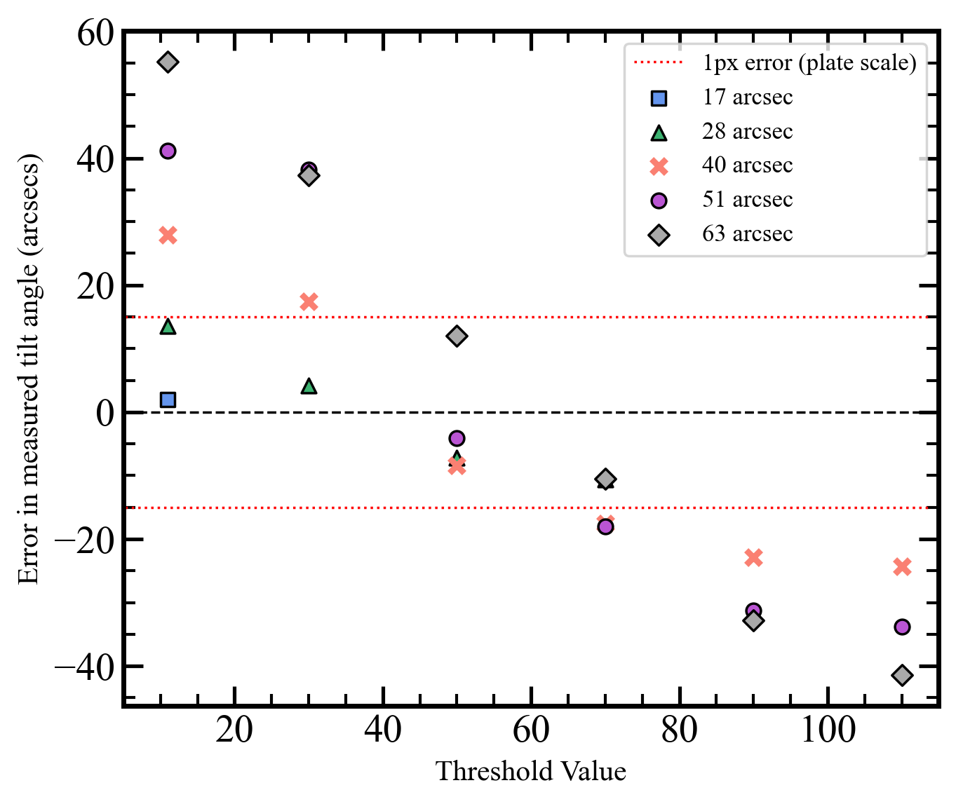
| (9) |
where is the circular aperture radius, is the focal length of the camera, and is the number of waves of tilt introduced across the pupil diameter for a lateral displacement of . The experimental results in Figure 10 for the best measurement conditions produce a value of , which is an error in tilt measurement of approximately .
3.3 Discussion
As demonstrated, the behaviour of an event-based sensor changes depending on the level of background illumination. Ideally, the background illumination will have a higher illumination relative to the tip-tilt signal level in order to minimise extra events being triggered due to shot noise, whilst still minimising noise around the signal source from leak events. For on-sky applications, this is advantageous for daytime wavefront sensing. Appropriate adjusting of the event-based detector’s threshold values is fundamental to minimise this error term. The two noise sources can be balanced to optimise the noise output of the event-based detector. This is a significant benefit to tip-tilt sensing in a wider range of conditions, including daytime operations for free space optical communications.
The average position tracker algorithm was able to update the tilt measurements with each event, making full use of the high speed measurement capabilities. This enabled the measurement of tilt down to an error of approximately 1 pixel, once the event threshold values were appropriately chosen. For LGS tip-tilt sensing, this accuracy is advantageous when measuring small scale differential tip-tilt as in the time delay method.
The error contributions of the event-based sensor to its application to the time-delay method include some clear differences to that of a traditional frame-based sensor. The accumulated error due to the integration time is not a factor in this operating principle, as the operating principle of event-based detectors does not involve capturing frames. Whilst this theoretically would increase the sky coverage of an event-based wavefront sensor, it also needs to be considered whether the brightness changes are significant enough to trigger sufficient events (this item will be studied in future work). Additionally, the lower data bandwidth of an event stream increases the speed at which real-time wavefront calculations can be made. However, small movements require extra consideration when locating the centre of gravity of a spot on the sensor. Where a classical detector shows the whole spot area at all times, an event-based detector only displays the edges of the spot since the central area might not be changing brightness. This can contribute to the overall error of measured tip-tilt if the spot-tracking algorithm is not designed to properly handle this output. This could limit how accurately small tip-tilt movements could be measured using an event-based sensor, and requires further exploration.
4 Conclusion
The tip-tilt retrieval problem arises out of the need to measure tip-tilt on a LGS. The time-delay method is a proposed approach to address this challenge. However, the differential tip-tilt (that results from the time delay between upwards and downwards propagation of a LGS) would cause LGS spot movements with very small magnitudes, which are difficult to detect. The results in this paper indicate that the event-based sensor could be used to detect such small movements due to its increased sensitivity and lower noise levels. Future work in this area will include modifications on the experimental set-up to reduce the plate scale and confirm the detector’s capability for measuring tip-tilt on the milliarcsecond scale to further the investigation of its application to the time delay method.
Based on this research, event-based detectors pose an advantage for daytime wavefront sensing due to their dynamic range. The experiments conducted demonstrated how increasing the overall illumination, (daytime sky background), enables the detection of a tip-tilt source with higher accuracy and more consistency. The event-based detector’s immunity to a constant sky background allows it to sense small movements despite noise levels. This is of particular use for laser communications applications which make use of adaptive optics in the daytime. The characterisation of the detector outlined in this report demonstrate how this can be achieved through appropriate choice of event threshold values.
Event-based detectors were tested to demonstrate the effect of key characteristics in the application of tip-tilt retrieval. A test bench was set up with a CenturyArks event-based detector. The detector’s logarithmic response to changes in illumination has been characterised, which allows for a more informed choice when tuning the event threshold values and compensation of noise sources. This enables the optimisation of the application of event-based detectors to different wavefront sensing conditions, like that of astronomy or daytime free space optical communications, with a comparative accuracy in tip-tilt measurement. The outcomes of this work suggest that the event-based sensor might be a strong contender for retrieving atmospheric tip-tilt information using laser guide stars and the time delay method.
Disclosures
This material is based upon work supported by the Air Force Office of Scientific Research under award number FA2386-23-1-4006.
Code, Data, and Materials Availability
Data and code underlying the results presented in this paper are not publicly available at this time but may be obtained from the authors upon reasonable request.
Acknowledgments
The authors would like to thank Esteban Vera and Vicente Westerhout from Pontificia Universidad Católica de Valparaíso for the collaboration and very productive discussions about their experiences with event-based detectors.
References
- [1] Castro-Almazán, J. A., Alonso, Á., Fuensalida, J. J., Calia, D. B., Centrone, M., Montilla, I., Reyes, M., and Muñoz-Tuñón, C., “The bistatic geometry for na profiling with lgs at teide observatory,” in [Adaptive Optics Systems V ], 9909, 1129–1134, SPIE (2016).
- [2] Rigaut, F. and Gendron, E., “Laser guide star in adaptive optics-the tilt determination problem,” Astronomy and Astrophysics (ISSN 0004-6361), vol. 261, no. 2, p. 677-684. 261, 677–684 (1992).
- [3] Tyson, R. K., “Adaptive optics and ground-to-space laser communications,” Applied optics 35(19), 3640–3646 (1996).
- [4] Tyson, R. K., “Bit-error rate for free-space adaptive optics laser communications,” JOSA A 19(4), 753–758 (2002).
- [5] Beckers, J. M. and Cacciani, A., “Using laser beacons for daytime adaptive optics,” Experimental Astronomy 11, 133–143 (2001).
- [6] Primmerman, C. A., Murphy, D. V., Page, D. A., Zollars, B. G., and Barclay, H. T., “Compensation of atmospheric optical distortion using a synthetic beacon,” Nature 353(6340), 141–143 (1991).
- [7] Belen’kii, M. S., “Tilt angular anisoplanatism and a full-aperture tilt-measurement technique with a laser guide star,” Applied optics 39(33), 6097–6108 (2000).
- [8] Ragazzoni, R., “Propagation delay of a laser beacon as a tool to retrieve absolute tilt measurements,” The Astrophysical Journal 465(1), L73 (1996).
- [9] Calia, D. B., Centrone, M., Pinna, E., Alaluf, D., Martinez, N., Osborn, J., Hackenberg, W., Townson, M., Faccini, M., Di Paola, A., et al., “Canapy: Satcomm lgs-ao experimental platform with laser uplink pre-compensation,” in [International Conference on Space Optics—ICSO 2020 ], 11852, 536–546, SPIE (2021).
- [10] Janout, P., Rey, N. M., and Bonaccini, D., “Canapy facility: opto-mechanical design and requirements for optimal visible systems lgs-ao,” Ground-based and Airborne Telescopes IX. Ed. by Heather K. Marshall, Jason Spyromilio, and Tomonori Usuda 12182, 1218226 (2022).
- [11] Gallego, G., Delbrück, T., Orchard, G., Bartolozzi, C., Taba, B., Censi, A., Leutenegger, S., Davison, A. J., Conradt, J., Daniilidis, K., et al., “Event-based vision: A survey,” IEEE transactions on pattern analysis and machine intelligence 44(1), 154–180 (2020).
- [12] Lichtsteiner, P., Posch, C., and Delbruck, T., “A 128128 120 db 15 s latency asynchronous temporal contrast vision sensor,” IEEE journal of solid-state circuits 43(2), 566–576 (2008).
- [13] Posch, C., Matolin, D., and Wohlgenannt, R., “A qvga 143 db dynamic range frame-free pwm image sensor with lossless pixel-level video compression and time-domain cds,” IEEE Journal of Solid-State Circuits 46(1), 259–275 (2010).
- [14] Brandli, C., Berner, R., Yang, M., Liu, S.-C., and Delbruck, T., “A 240 180 130 db 3 s latency global shutter spatiotemporal vision sensor,” IEEE Journal of Solid-State Circuits 49(10), 2333–2341 (2014).
- [15] Finateu, T., Niwa, A., Matolin, D., Tsuchimoto, K., Mascheroni, A., Reynaud, E., Mostafalu, P., Brady, F., Chotard, L., LeGoff, F., et al., “5.10 a 1280 720 back-illuminated stacked temporal contrast event-based vision sensor with 4.86 m pixels, 1.066 geps readout, programmable event-rate controller and compressive data-formatting pipeline,” in [2020 IEEE International Solid-State Circuits Conference-(ISSCC) ], 112–114, IEEE (2020).
- [16] Son, B., Suh, Y., Kim, S., Jung, H., Kim, J.-S., Shin, C., Park, K., Lee, K., Park, J., Woo, J., et al., “4.1 a 640 480 dynamic vision sensor with a 9m pixel and 300meps address-event representation,” in [2017 IEEE International Solid-State Circuits Conference (ISSCC) ], 66–67, IEEE (2017).
- [17] Joubert, D., Hébert, M., Konik, H., and Lavergne, C., “Characterization setup for event-based imagers applied to modulated light signal detection,” Applied optics 58(6), 1305–1317 (2019).
- [18] Kong, F., Lambert, A., Joubert, D., and Cohen, G., “Shack-hartmann wavefront sensing using spatial-temporal data from an event-based image sensor,” Optics Express 28(24), 36159–36175 (2020).
- [19] Maqueda, A. I., Loquercio, A., Gallego, G., García, N., and Scaramuzza, D., “Event-based vision meets deep learning on steering prediction for self-driving cars,” in [Proceedings of the IEEE conference on computer vision and pattern recognition ], 5419–5427 (2018).
- [20] Camuñas-Mesa, L. A., Serrano-Gotarredona, T., and Linares-Barranco, B., “Event-driven sensing and processing for high-speed robotic vision,” in [2014 IEEE Biomedical Circuits and Systems Conference (BioCAS) Proceedings ], 516–519, IEEE (2014).
- [21] Tinch, L., Menon, N., Hirakawa, K., and McCloskey, S., “Event-based detection, tracking, and recognition of unresolved moving objects,” in [Advanced Maui Optical and Space Surveillance Technologies Conference ], (2022).
- [22] Ralph, N. O., Marcireau, A., Afshar, S., Tothill, N., van Schaik, A., and Cohen, G., “Astrometric calibration and source characterisation of the latest generation neuromorphic event-based cameras for space imaging,” arXiv preprint arXiv:2211.09939 (2022).
- [23] Afshar, S., Nicholson, A. P., van Schaik, A., and Cohen, G., “Event-based object detection and tracking for space situational awareness,” IEEE Sensors Journal 20(24), 15117–15132 (2020).
- [24] Cohen, G., Afshar, S., and van Schaik, A., “Approaches for astrometry using event-based sensors,” in [Advanced Maui Optical and Space Surveillance (AMOS) Technologies Conference ], 25 (2018).
- [25] Cohen, G., Afshar, S., Morreale, B., Bessell, T., Wabnitz, A., Rutten, M., and van Schaik, A., “Event-based sensing for space situational awareness,” The Journal of the Astronautical Sciences 66(2), 125–141 (2019).
- [26] Krüger, J. and Kamiński, K., “Astrometric tests based on data from event-based sensor camera,” in [XXXIX Polish Astronomical Society Meeting ], 10, 72–74 (2020).
- [27] Grose, M., Schmidt, J. D., and Hirakawa, K., “Convolutional neural network for improved event-based shack-hartmann wavefront reconstruction,” Applied Optics 63, E35 (Apr. 2024).
- [28] Ziemann, M. R., Rathbun, I., and Metzler, C. A., “A learning-based approach to event-based shack-hartmann wavefront sensing,” in [Unconventional Imaging, Sensing, and Adaptive Optics 2024 ], Bose-Pillai, S. R., Dolne, J. J., and Kalensky, M., eds., 61, SPIE (Oct. 2024).
- [29] Graca, R. and Delbruck, T., “Unraveling the paradox of intensity-dependent dvs pixel noise,” arXiv preprint arXiv:2109.08640 (2021).
- [30] Hasinoff, S. W., “Photon, poisson noise,” in [Computer vision: a reference guide ], 980–982, Springer (2021).
- [31] Graça, R., McReynolds, B., and Delbruck, T., “Shining light on the dvs pixel: A tutorial and discussion about biasing and optimization,” in [Proceedings of the IEEE/CVF Conference on Computer Vision and Pattern Recognition ], 4045–4053 (2023).
- [32] Zhang, P., Ge, Z., Song, L., and Lam, E. Y., “Neuromorphic imaging with density-based spatiotemporal denoising,” IEEE Transactions on Computational Imaging 9, 530–541 (2023).
- [33] Padala, V., Basu, A., and Orchard, G., “A noise filtering algorithm for event-based asynchronous change detection image sensors on truenorth and its implementation on truenorth,” Frontiers in Neuroscience 12 (Mar. 2018).
- [34] Cockram, M. and Martínez Rey, N., “Characterising an event-based detector for applications to wavefront sensing,” in [Adaptive Optics Systems IX ], Schmidt, D., Vernet, E., and Jackson, K. J., eds., 269, SPIE (Aug. 2024).
- [35] Wyant, J. C. and Creath, K., “Basic wavefront aberration theory for optical metrology,” Applied optics and optical engineering 11(part 2), 28–39 (1992).