This paper was converted on www.awesomepapers.org from LaTeX by an anonymous user.
Want to know more? Visit the Converter page.

Error Propagation and Overhead Reduced Channel Estimation for RIS-Aided Multi-User mmWave Systems

(Invited Paper)
Zhendong Peng\text{Zhendong Peng}^{*}
Cunhua Pan\text{Cunhua Pan}^{\ddagger} Gui Zhou\text{Gui Zhou}^{\dagger} Hong Ren\text{Hong Ren}^{\ddagger}
University of Electronic Science and Technology of China
China Southeast University China
Friedrich-Alexander-University Erlangen-Nürnberg
Germany
Email: [email protected], {cpan, hren}@seu.edu.cn, [email protected]
Abstract

In this paper, we propose a novel two-stage based uplink channel estimation strategy with reduced pilot overhead and error propagation for a reconfigurable intelligent surface (RIS)-aided multi-user (MU) millimeter wave (mmWave) system. Specifically, in Stage I, with the carefully designed RIS phase shift matrix and introduced matching matrices, all users jointly estimate the correlation factors between different paths of the common RIS-base station (BS) channel, which achieves significant multi-user diversity gain. Then, the inherent scaling ambiguity and angle ambiguity of the mmWave cascaded channel are utilized to construct an ambiguous common RIS-BS channel composed of the estimated correlation factors. In Stage II, with the constructed ambiguous common RIS-BS channel, each user uses reduced pilots to estimate their specific user-RIS channel independently so as to obtain the entire cascaded channel. The theoretical number of pilots required for the proposed method is analyzed and the simulation results are presented to validate the effectiveness of this strategy.

Index Terms:
Reconfigurable intelligent surface, channel estimation, multi-user systems, millimeter wave

I Introduction

Reconfigurable intelligent surface (RIS) technology is envisioned to be a promising technique for enhancing the spectrum and energy efficiency of 6G-and-beyond communications with relative low hardware cost and energy consumption [1, 2, 3]. To reap the benefits promised by RIS, accurate channel state information (CSI) is required, which is challenging to achieve due to the lack of complex signal process ability of the RIS.

Recently, there have been many contributions on channel estimation for RIS-aided communication systems. Most work focused mainly on single-user system [4], but it might be not appropriate to apply the methods developed for this case to multi-user system directly since the pilot overhead would be prohibitively large, which is proportional to the number of users. On the other hand, for multi-user system, the correlation relationship among different user’s cascaded channel has been exploited to enhance the estimation performance [5] and reduce the pilot overhead of channel estimation significantly [6, 7, 8]. Specifically, for unstructured channel models, other users use reduced pilots to estimate their scaling coefficients with respect to the typical user so as to obtain the corresponding cascaded channels [6, 7]. Similarly, for structured channel models, other users’ cascaded channel can be estimated effectively with the re-parameterized common BS-RIS channel, which is constructed based on the estimated typical user’s cascaded channel [8]. However, these three methods mentioned above have a common issue that the existence of channel estimation error from the typical user in the previous stage will deteriorate the estimation accuracy of other users in the next stage, which is known as error propagation. An optional method to suppress this error propagation effect is the careful selection of the typical user. The typical user can be chosen as the closest one to the RIS for the less severe path loss. In addition, large number of pilots are usually allocated to the typical user so as to ensure the more accurate estimation performance of the typical user. However, these operations introduce the extra complexity to the system and consume excessive pilot overhead for the estimation of the typical user. Once the estimated CSI of the typical user is inaccurate, the estimation performance of the multi-user system will be severely degraded.

Motivated by the above, in this paper, we develop a two-stage based uplink cascaded channel estimation strategy without choosing the typical user for an RIS-aided millimeter wave (mmWave) multi-user system. In Stage I, with the carefully designed RIS phase shift matrix and the introduced matching matrices, all users jointly estimate the correlation factors between different paths of the common RIS-BS channel, which achieves multi-user diversity gain and suppresses the negative error propagation impact. Then, we utilize the inherent scaling ambiguity and angle ambiguity properties of the mmWave cascaded channel to construct an ambiguous common RIS-BS channel composed of the obtained correlation factors. In Stage II, based on the constructed common RIS-BS channel, each user only uses reduced pilots to estimate their specific user-RIS channel independently so as to obtain the full CSI of the cascaded channel. Lastly, we analyze the theoretical minimum number of pilots required for the strategy and present the corresponding simulation results for the proposed method.

Notations: For a matrix 𝐀\mathbf{A} of arbitrary size, 𝐀\mathbf{A}^{*}, 𝐀T\mathbf{A}^{\mathrm{T}}, 𝐀H\mathbf{A}^{\mathrm{H}}, 𝐀\mathbf{A}^{\mathrm{\dagger}}, and vec(𝐀)\mathrm{vec}(\mathbf{A}) stand for the conjugate, transpose, conjugate transpose, pseudo-inverse, and vectorization of 𝐀\mathbf{A}. The mm-th row of 𝐀\mathbf{A} is denoted by 𝐀(m,:)\mathbf{A}_{(m,:)}. Additionally, the Khatri-Rao product and Hadamard product between two matrices 𝐀\mathbf{A} and 𝐁\mathbf{B} are denoted by 𝐀𝐁\mathbf{A}\diamond\mathbf{B} and 𝐀𝐁\mathbf{A}\odot\mathbf{B}, respectively. 𝐈\mathbf{I} and 𝟎\mathbf{0} denote an identity matrix and an all-zero matrix with appropriate dimensions, respectively. For a vector 𝐚\mathbf{a}, [𝐚]m:n[\mathbf{a}]_{m:n} denotes the subvector containing from the mm-th element to the nn-th element of 𝐚\mathbf{a}, respectively. The symbol 𝐚||\mathbf{a}|| represents the Euclidean norm of 𝐚\mathbf{a}. Diag{𝐚}\mathrm{Diag}\{\mathbf{a}\} is a diagonal matrix with the entries of 𝐚\mathbf{a} on its diagonal. The inner product between two vectors 𝐚\mathbf{a} and 𝐛\mathbf{b} is denoted by 𝐚,𝐛𝐚H𝐛\left\langle\mathbf{a},\mathbf{b}\right\rangle\triangleq\mathbf{a}^{\mathrm{H}}\mathbf{b}. i1\mathrm{i}\triangleq\sqrt{-1} is the imaginary unit. \mathbb{C} represents the set of complex numbers.

II System Model

We consider a narrow-band time-division duplex (TDD) mmWave system, in which KK single-antenna users communicate with a BS equipped with an NN-antenna ULA. To improve the communication performance, an RIS equipped with a passive reflecting ULA of dimension MM is deployed. In addition, the direct channel between the BS and users are assumed to be blocked.

II-A Transmission model

Denote 𝐇N×M\mathbf{H}\in\mathbb{C}^{N\times M} as the channel matrix between the RIS and the BS, and 𝐡kM×1\mathbf{h}_{k}\in\mathbb{C}^{M\times 1} as the channel matrix between user kk and the RIS, respectively. The set of users is defined as 𝒦={1,,K}\mathcal{K}=\{1,\ldots,K\}. Denote 𝐞tM×1\mathbf{e}_{t}\in\mathbb{C}^{M\times 1} as the phase shift vector of the RIS in time slot tt. During the uplink transmission, the received signal from user kk at the BS in time slot tt, is expressed as

𝐲k(t)\displaystyle\mathbf{y}_{k}(t) =𝐇Diag{𝐞t}𝐡kPsk(t)+𝐧k(t)\displaystyle=\mathbf{H}\mathrm{Diag}\{\mathbf{e}_{t}\}\mathbf{h}_{k}\sqrt{P}s_{k}(t)+\mathbf{n}_{k}(t)
=𝐇Diag{𝐡k}𝐞tPsk(t)+𝐧k(t)\displaystyle=\mathbf{H}\mathrm{Diag}\{\mathbf{h}_{k}\}\mathbf{e}_{t}\sqrt{P}s_{k}(t)+\mathbf{n}_{k}(t)
𝐆k𝐞tPsk(t)+𝐧k(t),\displaystyle\triangleq\mathbf{G}_{k}\mathbf{e}_{t}\sqrt{P}s_{k}(t)+\mathbf{n}_{k}(t), (1)

where sk(t)s_{k}(t) is the pilot symbol of user kk and 𝐧k(t)N𝒞𝒩(𝟎,δ2𝐈N)\mathbf{n}_{k}(t)\in\mathbb{C}^{N}\sim\mathcal{CN}(\mathbf{0},\delta^{2}\mathbf{I}_{N}) is the corresponding additive white Gaussian noise (AWGN) with power δ2\delta^{2}. PP represents the transmit power. 𝐆k=𝐇Diag{𝐡k}\mathbf{G}_{k}=\mathbf{H}\mathrm{Diag}\{\mathbf{h}_{k}\} is the cascaded user-RIS-BS channel of user kk, needed to be estimated in this work.

II-B Channel model

First, we consider a typical ULA with QQ elements, whose steering vector 𝐚Q(x)Q×1\mathbf{a}_{Q}(x)\in\mathbb{C}^{Q\times 1} can be represented by

𝐚Q(x)=[1,ei2πx,,ei2π(Q1)x]T.\mathbf{a}_{Q}(x)=[1,e^{-\mathrm{i}2\pi x},\ldots,e^{-\mathrm{i}2\pi(Q-1)x}]^{\mathrm{T}}. (2)

The variable xx is regarded as the spatial frequency and there exists a one-to-one relationship between the spatial frequency xx and the physical angle ϱ\mathfrak{\varrho} as x=dλccos(ϱ)x=\frac{d}{\lambda_{c}}\cos(\mathfrak{\varrho}) when assuming dλc/2d\leq\lambda_{c}/2. Here, λc\lambda_{c} is the carrier wavelength and dd is the element spacing. In the remainder of the paper we will refer to the angle information as spatial frequency for simplicity.

Due to the limited scattering characteristics in the mmWave environment, we use the geometric channel model to rewrite the channel matrices in (1), i.e., 𝐇\mathbf{H} and 𝐡k\mathbf{h}_{k} as

𝐇\displaystyle\mathbf{H} =l=1Lαl𝐚N(ψl)𝐚MH(ωl)=𝐀N𝚲𝐀MH,\displaystyle=\sum_{l=1}^{L}\alpha_{l}\mathbf{a}_{N}(\psi_{l})\mathbf{a}_{M}^{\mathrm{H}}(\omega_{l})=\mathbf{A}_{N}\boldsymbol{\Lambda}\mathbf{A}_{M}^{\mathrm{H}}, (3)
𝐡k\displaystyle\mathbf{h_{\mathit{k}}} =j=1Jkβk,j𝐚M(φk,j)=𝐀M,k𝜷k,k𝒦,\displaystyle=\sum_{j=1}^{J_{k}}\beta_{k,j}\mathbf{a}_{M}(\varphi_{k,j})=\mathbf{A}_{M,k}\boldsymbol{\beta}_{k},\forall k\in\mathcal{K}, (4)

where LL and JkJ_{k} denote the number of propagation paths (scatterers) between the BS and the RIS, and between the RIS and user kk, respectively. In addition, αl\alpha_{l}, ψl\psi_{l} and ωl\omega_{l} are the complex path gain, AoA, and AoD of the ll-th path in the common RIS-BS channel, respectively. Similarly, βk,j\beta_{k,j} and φk,j\varphi_{k,j} represent the complex path gain and AoA of the jj-th path in the user kk-RIS channel, respectively. Moreover, 𝐀N=[𝐚N(ψ1),,𝐚N(ψL)]N×L\mathbf{A}_{N}=[\mathbf{a}_{N}(\psi_{1}),\ldots,\mathbf{a}_{N}(\psi_{L})]\in\mathbb{C}^{N\times L}, 𝐀M=[𝐚M(ω1),,𝐚M(ωL)]M×L\mathbf{A}_{M}=[\mathbf{a}_{M}(\omega_{1}),\ldots,\mathbf{a}_{M}(\omega_{L})]\in\mathbb{C}^{M\times L}, and 𝚲=Diag{α1,,αL}L×L\boldsymbol{\Lambda}=\mathrm{Diag}\{\alpha_{1},\ldots,\alpha_{L}\}\in\mathbb{C}^{L\times L} are the AoA steering (array response) matrix, AoD steering matrix and complex gain matrix of the common RIS-BS channel, respectively, and 𝐀M,k=[𝐚M(φk,1),,𝐚M(φk,Jk)]M×Jk\mathbf{A}_{M,k}=[\mathbf{a}_{M}(\varphi_{k,1}),\ldots,\mathbf{a}_{M}(\varphi_{k,J_{k}})]\in\mathbb{C}^{M\times J_{k}} and 𝜷k=[βk,1,,βk,Jk]TJk×1\boldsymbol{\beta}_{k}=[\beta_{k,1},\ldots,\beta_{k,J_{k}}]^{\mathrm{T}}\in\mathbb{C}^{J_{k}\times 1} are the AoA steering matrix and complex gain vector of the specific user kk-RIS channel, respectively.

Combining (3) and (4), the cascaded channel 𝐆k\mathbf{G}_{k} in (1) can be rewritten as

𝐆k=𝐀N𝚲𝐀MHDiag{𝐀M,k𝜷k},k𝒦.\mathbf{G}_{k}=\mathbf{A}_{N}\boldsymbol{\Lambda}\mathbf{A}_{M}^{\mathrm{H}}\mathrm{Diag}\{\mathbf{A}_{M,k}\boldsymbol{\beta}_{k}\},\forall k\in\mathcal{K}. (5)

III Two-Stage Based Cascaded Channel Estimation for a Multi-user System without Choosing a Typical User

In this section, a two-stage based uplink cascaded channel estimation strategy without choosing a typical user is proposed. Specifically, in Stage I, an ambiguous common RIS-BS channel is constructed by all users jointly so as to achieve multi-user diversity gain and suppress the impact of error propagation. In Stage II, each user only needs to estimate the specific user-RIS channel to obtain full CSI of the cascaded channel. Finally, the required pilot overhead is analyzed.

III-A Stage I: Estimation of the Ambiguous Common RIS-BS Channel

In this subsection, we present the details on the estimation of the ambiguous common RIS-BS channel, seen as a re-parameterized common RIS-BS channel.

During Stage I, with the carefully designed RIS phase shift coefficients, all users transmit the training pilots simultaneously so as to achieve the multi-user diversity gain. Assume the pilot symbols satisfy sk(t)=1s_{k}(t)=1 for k𝒦\forall k\in\mathcal{K}, and the transmitted power of each user PP is the same, which equals to 11, so that the received signal at the BS can be expressed as

𝐲(t)\displaystyle\mathbf{y}(t) =𝐲1(t)++𝐲k(t)++𝐲K(t)+𝐧(t)\displaystyle=\mathbf{y}_{1}(t)+...+\mathbf{y}_{k}(t)+...+\mathbf{y}_{K}(t)+\mathbf{n}(t)
=𝐇Diag{𝐡1}𝐞t++𝐇Diag{𝐡K}𝐞t+𝐧(t)\displaystyle=\mathbf{H}\mathrm{Diag}\{\mathbf{h}_{1}\}\mathbf{e}_{t}+...+\mathbf{H}\mathrm{Diag}\{\mathbf{h}_{K}\}\mathbf{e}_{t}+\mathbf{n}(t)
=𝐇Diag{𝐡}𝐞t+𝐧(t),\displaystyle=\mathbf{H}\mathrm{Diag}\{\mathbf{h}\}\mathbf{e}_{t}+\mathbf{n}(t), (6)

where 𝐡k=1K𝐡k\mathbf{h}\triangleq\sum_{k=1}^{K}\mathbf{h}_{k} is treated as the equivalent user-RIS channel, 𝐧(t)N×1𝒞𝒩(0,δ2𝐈)\mathbf{n}(t)\in\mathbb{C}^{N\times 1}\sim\mathcal{CN}(0,\delta^{2}\mathbf{I}) is the AWGN at the BS. Stacking VV time slots of (6), the received matrix 𝐘=[𝐲(1),𝐲(2),,𝐲(V)]N×V\mathbf{Y}=\left[\mathbf{y}(1),\mathbf{y}(2),...,\mathbf{y}(V)\right]\in\mathbb{C}^{N\times V} is expressed as

𝐘\displaystyle\mathbf{Y} =𝐇Diag{𝐡}[𝐞1,𝐞2,,𝐞V]+[𝐧(1),𝐧(2),,𝐧(V)]\displaystyle=\mathbf{H}\mathrm{Diag}\{\mathbf{h}\}[\mathbf{e}_{1},\mathbf{e}_{2},\ldots,\mathbf{e}_{V}]+[\mathbf{n}(1),\mathbf{n}(2),...,\mathbf{n}(V)]
=𝐀N𝚲𝐀MHDiag{𝐡}𝐄+𝐍,\displaystyle=\mathbf{A}_{N}\boldsymbol{\Lambda}\mathbf{A}_{M}^{\mathrm{H}}\mathrm{Diag}\{\mathbf{h}\}\mathbf{E}+\mathbf{N}, (7)

where 𝐄=[𝐞1,𝐞2,𝐞V]M×V\mathbf{E}=\left[\mathbf{e}_{1},\mathbf{e}_{2}\ldots,\mathbf{e}_{V}\right]\in\mathbb{C}^{M\times V} is the RIS phase shift matrix during this stage and 𝐍k=[𝐧(1),,𝐧(V)]N×V\mathbf{N}_{k}=\left[\mathbf{n}(1),\ldots,\mathbf{n}(V)\right]\in\mathbb{C}^{N\times V}.

III-A1 Common AoAs estimation

Estimating the AoA steering matrix of the common RIS-BS channel, i.e., 𝐀N\mathbf{A}_{N}, from (7) is a classical directional of arrival (DOA) estimation problem in array processing, and can be solved by many mature signal processing techniques [4]. Due to the large scale antenna arrays employed at the BS with typically LNL\ll N, the DFT-based method in [8] can be adopted to obtain the estimate of the common AoA steering matrix.

Denote the estimate of 𝐀N\mathbf{A}_{N} as 𝐀^N=[𝐚N(ψ^1),,𝐚N(ψ^L)]N×L\mathbf{\widehat{A}}_{N}=[\mathbf{a}_{N}(\widehat{\psi}_{1}),\ldots,\mathbf{a}_{N}(\widehat{\psi}_{L})]\in\mathbb{C}^{N\times L}. Due to the property that rank(𝐀^N)=L\mathrm{rank}(\mathbf{\widehat{A}}_{N})=L [9], by substituting 𝐀N=𝐀^N+Δ𝐀N\mathbf{A}_{N}=\mathbf{\widehat{A}}_{N}+\Delta\mathbf{A}_{N}, we can obtain the equivalent received matrix 𝐀^N𝐘\mathbf{\widehat{A}}_{N}^{\mathrm{\dagger}}\mathbf{Y} as

𝐀^N𝐘=\displaystyle\mathbf{\widehat{A}}_{N}^{\mathrm{\dagger}}\mathbf{Y}= 𝚲𝐀MHDiag{𝐡}𝐄+𝐀^N𝐍¯L×V,\displaystyle\boldsymbol{\Lambda}\mathbf{A}_{M}^{\mathrm{H}}\mathrm{Diag}\{\mathbf{h}\}\mathbf{E}+\mathbf{\widehat{A}}_{N}^{\mathrm{\dagger}}\bar{\mathbf{N}}\in\mathbb{C}^{L\times V}, (8)

where Δ𝐀N𝐀N𝐀^N\Delta\mathbf{A}_{N}\triangleq\mathbf{A}_{N}-\mathbf{\widehat{A}}_{N} is treated as the estimation error between the common AoA and its estimate, and 𝐍¯𝐍+Δ𝐀N𝚲𝐀MHDiag{𝐡}𝐄\bar{\mathbf{N}}\triangleq\mathbf{N}+\Delta\mathbf{A}_{N}\boldsymbol{\Lambda}\mathbf{A}_{M}^{\mathrm{H}}\mathrm{Diag}\{\mathbf{h}\}\mathbf{E} represents the equivalent noise matrix.

III-A2 Correlation relationship between different paths

With the estimated common AoA, i.e., 𝐀^N\mathbf{\widehat{A}}_{N}, a correlation relationship between different paths in the common RIS-BS channel will be revealed, which helps us to construct the ambiguous common RIS-BS channel. Specifically, calculating the ll-th row and the rr-th row of 𝐀^N𝐘\mathbf{\widehat{A}}_{N}^{\mathrm{\dagger}}\mathbf{Y} in (8), and then taking their conjugate transpose, we have

[(𝐀^N𝐘)l,:]H\displaystyle[(\mathbf{\widehat{A}}_{N}^{\mathrm{\dagger}}\mathbf{Y})_{l,:}]^{\mathrm{H}} =[(𝚲𝐀MH)l,:Diag{𝐡}𝐄]H+[(𝐀^N𝐍¯)l,:]H\displaystyle=[(\boldsymbol{\Lambda}\mathbf{A}_{M}^{\mathrm{H}})_{l,:}\mathrm{Diag}\{\mathbf{h}\}\mathbf{E}]^{\mathrm{H}}+[(\mathbf{\widehat{A}}_{N}^{\mathrm{\dagger}}\bar{\mathbf{N}})_{l,:}]^{\mathrm{H}}
=𝐄HDiag{𝐡}𝐚M(ωl)αl+𝐧~l,\displaystyle=\mathbf{E}^{\mathrm{H}}\mathrm{Diag}\{\mathbf{h}^{*}\}\mathbf{a}_{M}(\omega_{l})\alpha_{l}^{*}+\mathbf{\tilde{n}}_{l}, (9)
[(𝐀^N𝐘)r,:]H\displaystyle{}[(\mathbf{\widehat{A}}_{N}^{\mathrm{\dagger}}\mathbf{Y})_{r,:}]^{\mathrm{H}} =[(𝚲𝐀MH)r,:Diag{𝐡}𝐄]H+[(𝐀^N𝐍¯)r,:]H\displaystyle=[(\boldsymbol{\Lambda}\mathbf{A}_{M}^{\mathrm{H}})_{r,:}\mathrm{Diag}\{\mathbf{h}\}\mathbf{E}]^{\mathrm{H}}+[(\mathbf{\widehat{A}}_{N}^{\mathrm{\dagger}}\bar{\mathbf{N}})_{r,:}]^{\mathrm{H}}
=𝐄HDiag{𝐡}𝐚M(ωr)αr+𝐧~r,\displaystyle=\mathbf{E}^{\mathrm{H}}\mathrm{Diag}\{\mathbf{h}^{*}\}\mathbf{a}_{M}(\omega_{r})\alpha_{r}^{*}+\mathbf{\tilde{n}}_{r}, (10)

where 𝐧~l[(𝐀^N𝐍¯)l,:]H\mathbf{\tilde{n}}_{l}\triangleq[(\mathbf{\widehat{A}}_{N}^{\mathrm{\dagger}}\bar{\mathbf{N}})_{l,:}]^{\mathrm{H}} and 𝐧~r[(𝐀^N𝐍¯)r,:]H\mathbf{\tilde{n}}_{r}\triangleq[(\mathbf{\widehat{A}}_{N}^{\mathrm{\dagger}}\bar{\mathbf{N}})_{r,:}]^{\mathrm{H}}. Apparently, the dominant terms of [(𝐀^N𝐘)l,:]H[(\mathbf{\widehat{A}}_{N}^{\mathrm{\dagger}}\mathbf{Y})_{l,:}]^{\mathrm{H}} and [(𝐀^N𝐘)r,:]H[(\mathbf{\widehat{A}}_{N}^{\mathrm{\dagger}}\mathbf{Y})_{r,:}]^{\mathrm{H}}, i.e., 𝐄HDiag{𝐡}𝐚M(ωl)αl\mathbf{E}^{\mathrm{H}}\mathrm{Diag}\{\mathbf{h}^{*}\}\mathbf{a}_{M}(\omega_{l})\alpha_{l}^{*} and 𝐄HDiag{𝐡}𝐚M(ωr)αr\mathbf{E}^{\mathrm{H}}\mathrm{Diag}\{\mathbf{h}^{*}\}\mathbf{a}_{M}(\omega_{r})\alpha_{r}^{*}, contain the whole information regarding the ll-th path and the rr-th path, respectively, and there exists a relationship between these two terms, reflecting the correlation between the corresponding two paths.

To illustrate this correlation relationship, define a matching matrix 𝐀l\mathbf{A_{\mathit{l}}} for the ll-th path with respect to the rr-th path as

𝐀l\displaystyle\mathbf{A_{\mathit{l}}} 𝐀(ϖl)xl=[𝐔V(𝐚V(ϖl)𝟏VT)]H1V𝐔Vxl,\displaystyle\triangleq\mathbf{A}(\varpi_{l})x_{l}=[\mathbf{U}_{V}\odot(\mathbf{a}_{V}(\varpi_{l})\mathbf{1_{\mathit{V}}^{\mathrm{T}}})]^{\mathrm{H}}\frac{1}{V}\mathbf{U}_{V}x_{l}, (11)

where 𝐀(ϖl)[𝐔V(𝐚V(ϖl)𝟏VT)]H1V𝐔VV×V\mathbf{A}(\varpi_{l})\triangleq[\mathbf{U}_{V}\odot(\mathbf{a}_{V}(\varpi_{l})\mathbf{1_{\mathit{V}}^{\mathrm{T}}})]^{\mathrm{H}}\frac{1}{V}\mathbf{U}_{V}\in\mathbb{C}^{V\times V} is a complex nonlinear function of ϖl\varpi_{l}. 𝐔V\mathbf{U}_{V} is a V×VV\times V DFT matrix with the (n,m)(n,m)-th entry given by [𝐔V]n,m=ei2πV(n1)(m1)[\mathbf{U}_{V}]_{n,m}=e^{-\mathrm{i}\frac{2\pi}{V}(n-1)(m-1)}. 𝐚V(ϖl)\mathbf{a}_{V}(\varpi_{l}) can be regarded as the array manifold with dimension VV and 𝟏V\mathbf{1}_{\mathit{V}} is an all-one vector of size VV. Here, the rr-th path is treated as the reference path.111The reference index rr can be chosen based on the maximum received power criterion, i.e., r=argmaxp[1,L][(𝐀^N𝐘)p,:]H2r=\mathrm{arg}\max_{p\in[1,L]}||[(\mathbf{\widehat{A}}_{N}^{\mathrm{\dagger}}\mathbf{Y})_{p,:}]^{\mathrm{H}}||^{2}. ϖl\varpi_{l} and xlx_{l} are the rotation factor and scaling factor for the ll-th path with respect to the rr-th path, respectively, which are given by

ϖl=ωrωl,xl=αlαr.\varpi_{l}=\omega_{r}-\omega_{l},\leavevmode\nobreak\ x_{l}=\frac{\alpha_{l}^{*}}{\alpha_{r}^{*}}. (12)

Clearly, ϖl[2dRISλc,2dRISλc]\varpi_{l}\in[-2\frac{d_{\mathrm{RIS}}}{\lambda_{c}},2\frac{d_{\mathrm{RIS}}}{\lambda_{c}}]. During this stage, the RIS phase shift matrix 𝐄\mathbf{E} in (7) needs to be designed carefully, which should satisfy the following structure

𝐄=[𝐔VH¦ 0V×(MV)]H.\mathbf{E}=\left[\begin{array}[]{c}\mathbf{U}_{V}^{\mathrm{H}}\ \brokenvert\ \mathbf{0_{\mathit{V\times(M-V)}}}\end{array}\right]^{\mathrm{H}}. (13)

Where 𝐔VV×V\mathbf{U}_{V}\in\mathbb{C}^{V\times V} is a DFT matrix defined in (11), satisfying the constant modulus constraint. To show how the matching matrix 𝐀l\mathbf{A_{\mathit{l}}} works intuitively, the noise terms of (9) and (10) are momentarily omitted. Then, we have

𝐀l𝐄HDiag{𝐡}𝐚M(ωr)αr\displaystyle\mathbf{A_{\mathit{l}}}\mathbf{E}^{\mathrm{H}}\mathrm{Diag}\{\mathbf{h}^{*}\}\mathbf{a}_{M}(\omega_{r})\alpha_{r}^{*}
=\displaystyle= [𝐔V(𝐚V(ϖl)𝟏VT)]H1V𝐔Vxl𝐄HDiag{𝐡}𝐚M(ωr)αr\displaystyle[\mathbf{U}_{V}\odot(\mathbf{a}_{V}(\varpi_{l})\mathbf{1_{\mathit{V}}^{\mathrm{T}}})]^{\mathrm{H}}\frac{1}{V}\mathbf{U}_{V}x_{l}\mathbf{E}^{\mathrm{H}}\mathrm{Diag}\{\mathbf{h}^{*}\}\mathbf{a}_{M}(\omega_{r})\alpha_{r}^{*}
=\displaystyle= [(𝟏V𝐚VH(ϖl)𝐔VH][𝐈V¦𝟎V×(MV)]Diag{𝐡}𝐚M(ωr)αl\displaystyle[(\mathbf{1_{\mathit{V}}}\mathbf{a}_{V}^{\mathrm{H}}(\varpi_{l})\odot\mathbf{U}_{V}^{\mathrm{H}}][\mathbf{I_{\mathit{V}}}\brokenvert\mathbf{0_{\mathit{V\times(M-V)}}}]\mathrm{Diag}\{\mathbf{h}^{*}\}\mathbf{a}_{M}(\omega_{r})\alpha_{l}^{*}
=\displaystyle= [𝐈V𝐔VHDiag{𝐚V(ϖl)}¦𝟎V×(MV)]Diag{𝐡}𝐚M(ωr)αl\displaystyle[\mathbf{I_{\mathit{V}}}\mathbf{U}_{V}^{\mathrm{H}}\mathrm{Diag}^{*}\{\mathbf{a}_{V}(\varpi_{l})\}\brokenvert\mathbf{0_{\mathit{V\times(M-V)}}}]\mathrm{Diag}\{\mathbf{h}^{*}\}\mathbf{a}_{M}(\omega_{r})\alpha_{l}^{*}
=\displaystyle= 𝐄HDiag{𝐚M(ϖl)}Diag{𝐡}𝐚M(ωr)αl\displaystyle\mathbf{E}^{\mathrm{H}}\mathrm{Diag}^{*}\{\mathbf{a}_{M}(\varpi_{l})\}\mathrm{Diag}\{\mathbf{h}^{*}\}\mathbf{a}_{M}(\omega_{r})\alpha_{l}^{*}
=\displaystyle= 𝐄HDiag{𝐡}Diag{𝐚M(ϖl)}𝐚M(ωr)αl\displaystyle\mathbf{E}^{\mathrm{H}}\mathrm{Diag}\{\mathbf{h}^{*}\}\mathrm{Diag}\{\mathbf{a}_{M}(-\varpi_{l})\}\mathbf{a}_{M}(\omega_{r})\alpha_{l}^{*}
=\displaystyle= 𝐄HDiag{𝐡}𝐚M(ωl)αl,\displaystyle\mathbf{E}^{\mathrm{H}}\mathrm{Diag}\{\mathbf{h}^{*}\}\mathbf{a}_{M}(\omega_{l})\alpha_{l}^{*}, (14)

where the third equality is obtained using (𝐲𝐱H)𝐀=Diag{𝐲}𝐀Diag{𝐱}(\mathbf{yx^{\mathrm{H}}\mathrm{)}\odot A=\mathrm{Diag}\{y\}A\mathrm{Diag}^{*}\{x\}}. From Eq. (14), the term 𝐄HDiag{𝐡}𝐚M(ωl)αl\mathbf{E}^{\mathrm{H}}\mathrm{Diag}\{\mathbf{h}^{*}\}\mathbf{a}_{M}(\omega_{l})\alpha_{l}^{*} can be expressed as the result of the term 𝐄HDiag{𝐡}𝐚M(ωr)αr\mathbf{E}^{\mathrm{H}}\mathrm{Diag}\{\mathbf{h}^{*}\}\mathbf{a}_{M}(\omega_{r})\alpha_{r}^{*} via the linear transformation 𝐀l\mathbf{A_{\mathit{l}}}. Thus the correlation between the ll-th path and the rr-th path is depicted by the two variables of matching matrix 𝐀l\mathbf{A_{\mathit{l}}}, i.e., ϖl\varpi_{l} and xlx_{l}. By analogy, we conclude that the correlation relationship between any two paths in the common RIS-BS channel can be described by their rotation factors and scaling factors. Now we will show how to estimate these two kinds of factors, i.e., rotation factors and scaling factors, from the equivalent received signal 𝐀^N𝐘\mathbf{\widehat{A}}_{N}^{\mathrm{\dagger}}\mathbf{Y}.

III-A3 Estimation of the rotation factors and scaling factors

We still take the ll-th path and the rr-th path, i.e., the reference path, as an example to illustrate the method for estimating the rotation factors and scaling factors. Similar to Eq. (14), we process the received signal [(𝐀^N𝐘)r,:]H[(\mathbf{\widehat{A}}_{N}^{\mathrm{\dagger}}\mathbf{Y})_{r,:}]^{\mathrm{H}} in (10) via the linear transformation 𝐀l\mathbf{A_{\mathit{l}}} as

𝐀l[(𝐀^N𝐘)r,:]H\displaystyle\mathbf{A_{\mathit{l}}}[(\mathbf{\widehat{A}}_{N}^{\mathrm{\dagger}}\mathbf{Y})_{r,:}]^{\mathrm{H}} =𝐀l𝐄HDiag{𝐡}𝐚M(ωr)αr+𝐀l𝐧~r\displaystyle=\mathbf{A_{\mathit{l}}}\mathbf{E}^{\mathrm{H}}\mathrm{Diag}\{\mathbf{h}^{*}\}\mathbf{a}_{M}(\omega_{r})\alpha_{r}^{*}+\mathbf{A_{\mathit{l}}}\mathbf{\tilde{n}}_{r}
=𝐄HDiag{𝐡}𝐚M(ωl)αlΔ𝐧~r,\displaystyle=\mathbf{E}^{\mathrm{H}}\mathrm{Diag}\{\mathbf{h}^{*}\}\mathbf{a}_{M}(\omega_{l})\alpha_{l}^{*}-\Delta\mathbf{\tilde{n}}_{r}, (15)

where Δ𝐧~r𝐀l𝐧~r\Delta\mathbf{\tilde{n}}_{r}\triangleq-\mathbf{A_{\mathit{l}}}\mathbf{\tilde{n}}_{r}. By replacing 𝐄HDiag{𝐡}𝐚M(ωl)αl=𝐀l[(𝐀^N𝐘)r,:]H+Δ𝐧~r\mathbf{E}^{\mathrm{H}}\mathrm{Diag}\{\mathbf{h}^{*}\}\mathbf{a}_{M}(\omega_{l})\alpha_{l}^{*}=\mathbf{A_{\mathit{l}}}[(\mathbf{\widehat{A}}_{N}^{\mathrm{\dagger}}\mathbf{Y})_{r,:}]^{\mathrm{H}}+\Delta\mathbf{\tilde{n}}_{r} and 𝐀l=𝐀(ϖl)xl\mathbf{A_{\mathit{l}}}=\mathbf{A}(\varpi_{l})x_{l}, (9) is re-expressed as

[(𝐀^N𝐘)l,:]H\displaystyle[(\mathbf{\widehat{A}}_{N}^{\mathrm{\dagger}}\mathbf{Y})_{l,:}]^{\mathrm{H}} =𝐄HDiag{𝐡}𝐚M(ωl)αl+𝐧~l\displaystyle=\mathbf{E}^{\mathrm{H}}\mathrm{Diag}\{\mathbf{h}^{*}\}\mathbf{a}_{M}(\omega_{l})\alpha_{l}^{*}+\mathbf{\tilde{n}}_{l}
=𝐀(ϖl)xl[(𝐀^N𝐘)r,:]H+𝐧noise.\displaystyle=\mathbf{A}(\varpi_{l})x_{l}[(\mathbf{\widehat{A}}_{N}^{\mathrm{\dagger}}\mathbf{Y})_{r,:}]^{\mathrm{H}}+\mathbf{n}_{\mathrm{noise}}. (16)

Here, 𝐧noiseΔ𝐧~r+𝐧~l\mathbf{n}_{\mathrm{noise}}\triangleq\Delta\mathbf{\tilde{n}}_{r}+\mathbf{\tilde{n}}_{l} represents the corresponding noise vector. Moreover, denote [(𝐀^N𝐘)l,:]H[(\mathbf{\widehat{A}}_{N}^{\mathrm{\dagger}}\mathbf{Y})_{l,:}]^{\mathrm{H}} as 𝐲~l\mathbf{\tilde{y}}_{l} and 𝐀(ϖl)[(𝐀^N𝐘)r,:]H\mathbf{A}(\varpi_{l})[(\mathbf{\widehat{A}}_{N}^{\mathrm{\dagger}}\mathbf{Y})_{r,:}]^{\mathrm{H}} as 𝐁(ϖl)V\mathbf{B}(\varpi_{l})\in\mathbb{C}^{V}, (16) can be written as

𝐲~l=𝐁(ϖl)xl+𝐧noise.\mathbf{\tilde{y}}_{l}=\mathbf{B}(\varpi_{l})x_{l}+\mathbf{n}_{\mathrm{noise}}. (17)

So our aim is to estimate the rotation factor ϖl\varpi_{l} and scaling factor xlx_{l} with the received 𝐲~l\mathbf{\tilde{y}}_{l}, which can be achieved by solving the problem shown below as

(ϖl,xl)\displaystyle(\varpi_{l},x_{l}) =argminϖ[2dRISλc,2dRISλc],x𝐲~l𝐁(ϖ)x2,\displaystyle=\mathrm{arg}\min_{\varpi\in[-2\frac{d_{\mathrm{RIS}}}{\lambda_{c}},2\frac{d_{\mathrm{RIS}}}{\lambda_{c}}],x}||\mathbf{\tilde{y}}_{l}-\mathbf{B}(\varpi)x||^{2}, (18)

where 𝐁(ϖ)\mathbf{B}(\varpi) is an extremely complex nonlinear function with respect to ϖ\varpi. This problem is known as a separable nonlinear least squares (SNL-LS) problem, in which the optimal ϖl\varpi_{l} and xlx_{l} can be found via the following steps.

First, when the ϖ\varpi is fixed, the optimal xx is given by the least square (LS) solution, i.e., xopt=𝐁(ϖ)𝐲~lx_{\mathrm{opt}}=\mathbf{B}^{\dagger}(\varpi)\mathbf{\tilde{y}}_{l}. Then, by substituting xoptx_{\mathrm{opt}} into Problem (18), the optimal ϖ\varpi can be acquired by solving the new problem as

ϖl=argminϖ[2dRISλc,2dRISλc]𝐲~l𝐁(ϖ)𝐁(ϖ)𝐲~l2,\varpi_{l}=\mathrm{arg}\min_{\varpi\in[-2\frac{d_{\mathrm{RIS}}}{\lambda_{c}},2\frac{d_{\mathrm{RIS}}}{\lambda_{c}}]}||\mathbf{\tilde{y}}_{l}-\mathbf{B}(\varpi)\mathbf{B}^{\dagger}(\varpi)\mathbf{\tilde{y}}_{l}||^{2}, (19)

where the objective function of Problem (19), i.e., 𝐲~l𝐁(ϖ)𝐁(ϖ)𝐲~l2||\mathbf{\tilde{y}}_{l}-\mathbf{B}(\varpi)\mathbf{B}^{\dagger}(\varpi)\mathbf{\tilde{y}}_{l}||^{2}, can be simplified as

𝐲~l𝐁(ϖ)𝐁(ϖ)𝐲~l2\displaystyle||\mathbf{\tilde{y}}_{l}-\mathbf{B}(\varpi)\mathbf{B}^{\dagger}(\varpi)\mathbf{\tilde{y}}_{l}||^{2}
=\displaystyle= 𝐲~lH𝐲~l𝐲~lH𝐁(ϖ)𝐁(ϖ)𝐲~l\displaystyle\mathbf{\tilde{y}}_{l}^{\mathrm{H}}\mathbf{\tilde{y}}_{l}-\mathbf{\tilde{y}}_{l}^{\mathrm{H}}\mathbf{B}(\varpi)\mathbf{B}^{\dagger}(\varpi)\mathbf{\tilde{y}}_{l}
=\displaystyle= 𝐲~lH𝐲~l𝐲~lH𝐁(ϖ)[𝐁H(ϖ)𝐁(ϖ)]1𝐁H(ϖ)𝐲~l\displaystyle\mathbf{\tilde{y}}_{l}^{\mathrm{H}}\mathbf{\tilde{y}}_{l}-\mathbf{\tilde{y}}_{l}^{\mathrm{H}}\mathbf{B}(\varpi)[\mathbf{B}^{\mathrm{H}}(\varpi)\mathbf{B}(\varpi)]^{-1}\mathbf{B}^{\mathrm{H}}(\varpi)\mathbf{\tilde{y}}_{l}
=\displaystyle= 𝐲~lH𝐲~lϕ(ϖ)|𝐲~l,𝐁(ϖ)|2,\displaystyle\mathbf{\tilde{y}}_{l}^{\mathrm{H}}\mathbf{\tilde{y}}_{l}-\phi(\varpi)\left|\left\langle\mathbf{\tilde{y}}_{l},\mathbf{B}(\varpi)\right\rangle\right|^{2}, (20)

where ϕ(ϖ)[𝐁H(ϖ)𝐁(ϖ)]1\phi(\varpi)\triangleq[\mathbf{B}^{\mathrm{H}}(\varpi)\mathbf{B}(\varpi)]^{-1}. With Eq. (20), Problem (19) is equivalent to the optimization problem as

ϖl=argmaxϖ[2dRISλc,2dRISλc]ϕ(ϖ)|𝐲~l,𝐁(ϖ)|2.\varpi_{l}=\mathrm{arg}\max_{\varpi\in[-2\frac{d_{\mathrm{RIS}}}{\lambda_{c}},2\frac{d_{\mathrm{RIS}}}{\lambda_{c}}]}\phi(\varpi)\left|\left\langle\mathbf{\tilde{y}}_{l},\mathbf{B}(\varpi)\right\rangle\right|^{2}. (21)

For Problem (21), one-dimension search method can be adopted to obtain the optimal ϖ\varpi, i.e., ϖl\varpi_{l}, whose performance depends on the number of search grids. Once the rotation factor ϖl\varpi_{l} is obtained by solving Problem (21), the scaling factor xlx_{l} is given by

xl=𝐁(ϖl)𝐲~l.x_{l}=\mathbf{B}^{\dagger}(\varpi_{l})\mathbf{\tilde{y}}_{l}. (22)

Finally, the rotation factors and the scaling factors for any paths in the common RIS-BS channel with respect to the reference path, i.e., the rr-th path, can be estimated. Specifically, for lr\forall l\neq r, the rotation factors and the scaling factors between the ll-th path and the rr-th path, i.e., ϖl\varpi_{l} and xlx_{l}, are obtained via the solution to Problem (21) and Eq. (22). While for l=rl=r, according to the definitions in (12), the corresponding rotation factor and the scaling factor are given by ϖr=0\varpi_{r}=0 and xr=1x_{r}=1.

III-A4 Construction of the common RIS-BS Channel

In previous subsections, we have shown that the rotation factors and scaling factors, i.e., ϖl\varpi_{l} and xlx_{l} for l={1,2,,L}\forall l=\{1,2,...,L\}, can be estimated effectively by all users jointly with the designed 𝐄\mathbf{E}. Based on the obtained parameters, an ambiguous complex gain matrix of the common RIS-BS channel, i.e., denoted by 𝚲s\boldsymbol{\Lambda}_{\mathrm{s}}, and an ambiguous AoD steering matrix of the common RIS-BS channel, i.e., denoted by 𝐀s\mathbf{A}_{\mathrm{s}}, are constructed as

𝚲s\displaystyle\boldsymbol{\Lambda}_{\mathrm{s}} Diag{x1,x2,,xL},\displaystyle\triangleq\mathrm{Diag}\{x_{1}^{*},x_{2}^{*},\ldots,x_{L}^{*}\}, (23)
𝐀s\displaystyle\mathbf{A}_{\mathrm{s}} [𝐚M(ϖ1),𝐚M(ϖ2),,𝐚M(ϖL)].\displaystyle\triangleq[\mathbf{a}_{M}(-\varpi_{1}),\mathbf{a}_{M}(-\varpi_{2}),\ldots,\mathbf{a}_{M}(-\varpi_{L})]. (24)

It is observed that the relationship between 𝚲s\boldsymbol{\Lambda}_{\mathrm{s}} and 𝚲\boldsymbol{\Lambda}, and the relationship between 𝐀s\mathbf{A}_{\mathrm{s}} and 𝐀M\mathbf{A}_{M} can be described as

𝚲s\displaystyle\boldsymbol{\Lambda}_{\mathrm{s}} =Diag{α1αr,α2αr,,αLαr}=1αr𝚲,\displaystyle=\mathrm{Diag}\{\frac{\alpha_{1}}{\alpha_{r}},\frac{\alpha_{2}}{\alpha_{r}},\ldots,\frac{\alpha_{L}}{\alpha_{r}}\}=\frac{1}{\alpha_{r}}\boldsymbol{\Lambda}, (25)
𝐀s\displaystyle\mathbf{A}_{\mathrm{s}} =[𝐚M(ω1ωr),𝐚M(ω2ωr),,𝐚M(ωLωr)]\displaystyle=[\mathbf{a}_{M}(\omega_{1}-\omega_{r}),\mathbf{a}_{M}(\omega_{2}-\omega_{r}),\ldots,\mathbf{a}_{M}(\omega_{L}-\omega_{r})]
=Diag{𝐚M(ωr)}𝐀M.\displaystyle=\mathrm{Diag}\{\mathbf{a}_{M}(-\omega_{r})\}\mathbf{A}_{M}. (26)

With the obtained 𝐀N\mathbf{A}_{N}, 𝚲s\boldsymbol{\Lambda}_{\mathrm{s}} and 𝐀s\mathbf{A}_{\mathrm{s}}, the corresponding ambiguous common RIS-BS channel, denoted by 𝐇s\mathbf{H}_{\mathrm{s}}, is naturally constructed as

𝐇s\displaystyle\mathbf{H}_{\mathrm{s}} 𝐀N𝚲s𝐀sH.\displaystyle\triangleq\mathbf{A}_{N}\boldsymbol{\Lambda}_{\mathrm{s}}\mathbf{A}_{\mathrm{s}}^{\mathrm{H}}. (27)

Then, substituting 𝚲=αr𝚲s\boldsymbol{\Lambda}=\alpha_{r}\boldsymbol{\Lambda}_{\mathrm{s}} and 𝐀M=Diag{𝐚M(ωr)}𝐀s\mathbf{A}_{M}=\mathrm{Diag}\{\mathbf{a}_{M}(\omega_{r})\}\mathbf{A}_{\mathrm{s}} into 𝐆k\mathbf{G}_{k} in (5), we have

𝐆k=\displaystyle\mathbf{G}_{k}= 𝐀N𝚲𝐀MHDiag{𝐀M,k𝜷k}\displaystyle\mathbf{A}_{N}\boldsymbol{\Lambda}\mathbf{A}_{M}^{\mathrm{H}}\mathrm{Diag}\{\mathbf{A}_{M,k}\boldsymbol{\beta}_{k}\}
=\displaystyle= 𝐀N(αr𝚲s)𝐀sHDiag{𝐚M(ωr)}Diag{𝐀M,k𝜷k}\displaystyle\mathbf{A}_{N}(\alpha_{r}\boldsymbol{\Lambda}_{\mathrm{s}})\mathbf{A}_{\mathrm{s}}^{\mathrm{H}}\mathrm{Diag}\{\mathbf{a}_{M}(-\omega_{r})\}\mathrm{Diag}\{\mathbf{A}_{M,k}\boldsymbol{\beta}_{k}\}
=\displaystyle= 𝐀N𝚲s𝐀sHDiag{(Diag{𝐚M(ωr)}𝐀M,k)(αr𝜷k)}\displaystyle\mathbf{A}_{N}\boldsymbol{\Lambda}_{\mathrm{s}}\mathbf{A}_{\mathrm{s}}^{\mathrm{H}}\mathrm{Diag}\{(\mathrm{Diag}\{\mathbf{a}_{M}(-\omega_{r})\}\mathbf{A}_{M,k})(\alpha_{r}\boldsymbol{\beta}_{k})\}
=\displaystyle= 𝐀N𝚲s𝐀sHDiag{𝐀s,k𝜷s,k}\displaystyle\mathbf{A}_{N}\boldsymbol{\Lambda}_{\mathrm{s}}\mathbf{A}_{\mathrm{s}}^{\mathrm{H}}\mathrm{Diag}\{\mathbf{A}_{\mathrm{s},k}\boldsymbol{\beta}_{\mathrm{s},k}\}
=\displaystyle= 𝐇sDiag{𝐡s,k},k𝒦,\displaystyle\mathbf{H}_{\mathrm{s}}\mathrm{Diag}\{\mathbf{h}_{\mathrm{s},k}\},\forall k\in\mathcal{K}, (28)

where 𝐀s,kDiag{𝐚M(ωr)}𝐀M,k=[𝐚M(φk,1ωr),,𝐚M(φk,Jkωr)]M×Jk\mathbf{A}_{\mathrm{s},k}\triangleq\mathrm{Diag}\{\mathbf{a}_{M}(-\omega_{r})\}\mathbf{A}_{M,k}=[\mathbf{a}_{M}(\varphi_{k,1}-\omega_{r}),\ldots,\mathbf{a}_{M}(\varphi_{k,J_{k}}-\omega_{r})]\in\mathbb{C}^{M\times J_{k}} and 𝜷s,kαr𝜷k=[αrβk,1,,αrβk,Jk]TJk×1\boldsymbol{\beta}_{\mathrm{s},k}\triangleq\alpha_{r}\boldsymbol{\beta}_{k}=[\alpha_{r}\beta_{k,1},\ldots,\alpha_{r}\beta_{k,J_{k}}]^{\mathrm{T}}\in\mathbb{C}^{J_{k}\times 1} are the corresponding ambiguous AoA steering matrix and ambiguous complex gain vector of the specific user-RIS channel for user kk, respectively. Accordingly, 𝐡s,k𝐀s,k𝜷s,k=αrDiag{𝐚M(ωr)}𝐡k\mathbf{h}_{\mathrm{s},k}\triangleq\mathbf{A}_{\mathrm{s},k}\boldsymbol{\beta}_{\mathrm{s},k}=\alpha_{r}\mathrm{Diag}\{\mathbf{a}_{M}(-\omega_{r})\}\mathbf{h}_{k} is the corresponding ambiguous specific user-RIS channel for user kk, that must still be found. In next subsection we will show how to estimate 𝐡s,k\mathbf{h}_{\mathrm{s},k} for k𝒦\forall k\in\mathcal{K} with the constructed 𝐇s\mathbf{H}_{\mathrm{s}}, leading to a significant reduction in the pilot overhead.

III-B Stage II: Estimation of the Ambiguous Specific User-RIS Channel

In Stage II, the users are required to transmit the pilot sequences one by one for the estimation of the ambiguous specific user-RIS channel.

Without loss of generality, we consider an arbitrary kk from 𝒦\mathcal{K} and show how to estimate user kk’s ambiguous specific user-RIS channel, i.e., 𝐡s,k\mathbf{h}_{\mathrm{s},k}. Assume τk\tau_{k} pilots are allocated for user kk in this stage. In addition, assume the pilot symbols satisfy sk(t)=1s_{k}(t)=1 and the transmitted power PP equals to 11 as before. Then, with Eq. (28), the received signal from user kk at the BS in time slot tt can be expressed as

𝐲k(t)\displaystyle\mathbf{y}_{k}(t) =𝐆k𝐞t+𝐧k(t)\displaystyle=\mathbf{G}_{k}\mathbf{e}_{t}+\mathbf{n}_{k}(t)
=𝐇sDiag{𝐡s,k}𝐞t+𝐧k(t).\displaystyle=\mathbf{H}_{\mathrm{s}}\mathrm{Diag}\{\mathbf{h}_{\mathrm{s},k}\}\mathbf{e}_{t}+\mathbf{n}_{k}(t). (29)

For clear illustration, we still assume that the BS receives the pilot sequence from time slot 11 to time slot τk\tau_{k}, and thus the received matrix 𝐘k=[𝐲k(1),,𝐲k(τk)]N×τk\mathbf{Y}_{k}=\left[\mathbf{y}_{k}(1),\ldots,\mathbf{y}_{k}(\tau_{k})\right]\in\mathbb{C}^{N\times\tau_{k}} during user kk’s pilot transmission is expressed as

𝐘k\displaystyle\mathbf{Y}_{k} =𝐇sDiag{𝐡s,k}𝐄k+𝐍k\displaystyle=\mathbf{H}_{\mathrm{s}}\mathrm{Diag}\{\mathbf{h}_{\mathrm{s},k}\}\mathbf{E}_{k}+\mathbf{N}_{k}
=𝐀N𝚲s𝐀sHDiag{𝐡s,k}𝐄k+𝐍k,\displaystyle=\mathbf{A}_{N}\boldsymbol{\Lambda}_{\mathrm{s}}\mathbf{A}_{\mathrm{s}}^{\mathrm{H}}\mathrm{Diag}\{\mathbf{h}_{\mathrm{s},k}\}\mathbf{E}_{k}+\mathbf{N}_{k}, (30)

where 𝐄k=[𝐞1,,𝐞τk]M×τk\mathbf{E}_{k}=\left[\mathbf{e}_{1},\ldots,\mathbf{e}_{\tau_{k}}\right]\in\mathbb{C}^{M\times\tau_{k}} and 𝐍k=[𝐧k(1),,𝐧k(τk)]N×τk\mathbf{N}_{k}=\left[\mathbf{n}_{k}(1),\ldots,\mathbf{n}_{k}(\tau_{k})\right]\in\mathbb{C}^{N\times\tau_{k}}.

With the estimated common AoA steering matrix 𝐀^N\mathbf{\widehat{A}}_{N}, user kk’s received matrix is processed similarly to what was done for (8) as

𝐀^N𝐘k=𝚲s𝐀sHDiag{𝐡s,k}𝐄k+𝐀^N𝐍¯kL×τk,\mathbf{\widehat{A}}_{N}^{\mathrm{\dagger}}\mathbf{Y}_{k}=\boldsymbol{\Lambda}_{\mathrm{s}}\mathbf{A}_{\mathrm{s}}^{\mathrm{H}}\mathrm{Diag}\{\mathbf{h}_{\mathrm{s},k}\}\mathbf{E}_{k}+\mathbf{\widehat{A}}_{N}^{\mathrm{\dagger}}\bar{\mathbf{N}}_{k}\in\mathbb{C}^{L\times\tau_{k}}, (31)

where 𝐍¯k𝐍k+Δ𝐀N𝚲s𝐀sHDiag{𝐡s,k}\bar{\mathbf{N}}_{k}\triangleq\mathbf{N}_{k}+\Delta\mathbf{A}_{N}\boldsymbol{\Lambda}_{\mathrm{s}}\mathbf{A}_{\mathrm{s}}^{\mathrm{H}}\mathrm{Diag}\{\mathbf{h}_{\mathrm{s},k}\}. Then, vectorizing (31) and defining 𝐰k=vec(𝐀^N𝐘k)Lτk×1\mathbf{w}_{k}=\mathrm{vec}(\mathbf{\widehat{A}}_{N}^{\mathrm{\dagger}}\mathbf{Y}_{k})\in\mathbb{C}^{L\tau_{k}\times 1}, we have

𝐰k\displaystyle\mathbf{w}_{k} =vec(𝚲s𝐀sHDiag{𝐡s,k}𝐄k)+vec(𝐀^N𝐍¯k)\displaystyle=\mathrm{vec}(\boldsymbol{\Lambda}_{\mathrm{s}}\mathbf{A}_{\mathrm{s}}^{\mathrm{H}}\mathrm{Diag}\{\mathbf{h}_{\mathrm{s},k}\}\mathbf{E}_{k})+\mathrm{vec}(\mathbf{\widehat{A}}_{N}^{\mathrm{\dagger}}\bar{\mathbf{N}}_{k})
=(𝐄kT𝚲s𝐀sH)𝐡s,k+𝐧¯k\displaystyle=(\mathbf{E}_{k}^{\mathrm{T}}\diamond\boldsymbol{\Lambda}_{\mathrm{s}}\mathbf{A}_{\mathrm{s}}^{\mathrm{H}})\mathbf{h}_{\mathrm{s},k}+\bar{\mathbf{n}}_{k}
=𝐖k𝐡s,k+𝐧¯k,\displaystyle=\mathbf{W}_{k}\mathbf{h}_{\mathrm{s},k}+\bar{\mathbf{n}}_{k}, (32)

where 𝐖k(𝐄kT𝚲s𝐀sH)Lτk×M\mathbf{W}_{k}\triangleq(\mathbf{E}_{k}^{\mathrm{T}}\diamond\boldsymbol{\Lambda}_{\mathrm{s}}\mathbf{A}_{\mathrm{s}}^{\mathrm{H}})\in\mathbb{C}^{L\tau_{k}\times M} and 𝐧¯k\bar{\mathbf{n}}_{k} is the corresponding equivalent noise vector given by vec(𝐀^N𝐍¯k)Lτk×1\mathrm{vec}(\mathbf{\widehat{A}}_{N}^{\mathrm{\dagger}}\bar{\mathbf{N}}_{k})\in\mathbb{C}^{L\tau_{k}\times 1}. The second equality is obtained via vec(𝐀Diag{𝐛}𝐂)=(𝐂T𝐀)𝐛\mathrm{vec}(\mathbf{\mathbf{A}\mathrm{Diag}\{b\}C})=(\mathbf{\mathbf{C}^{\mathrm{T}}\diamond A})\mathbf{b}.

In particular, as illustrated in (28), 𝐀s,k=[𝐚M(φk,1ωr),,𝐚M(φk,Jkωr)]\mathbf{A}_{\mathrm{s},k}=[\mathbf{a}_{M}(\varphi_{k,1}-\omega_{r}),\ldots,\mathbf{a}_{M}(\varphi_{k,J_{k}}-\omega_{r})] where φk,jωr\varphi_{k,j}-\omega_{r} for j{1,,Jk}\forall j\in\{1,...,J_{k}\} lies within [2dRISλc,2dRISλc][-2\frac{d_{\mathrm{RIS}}}{\lambda_{c}},2\frac{d_{\mathrm{RIS}}}{\lambda_{c}}], thus we can formulate (32) as a JkJ_{k}-sparse signal recovery problem:

𝐰k\displaystyle\mathbf{w}_{k} =𝐖k𝐀s,k𝜷s,k+𝐧¯k=𝐖k𝐀𝐝k+𝐧¯k,\displaystyle=\mathbf{W}_{k}\mathbf{A}_{\mathrm{s},k}\boldsymbol{\beta}_{\mathrm{s},k}+\bar{\mathbf{n}}_{k}=\mathbf{W}_{k}\mathbf{A}\mathbf{d}_{k}+\bar{\mathbf{n}}_{k}, (33)

where 𝐀𝐝k\mathbf{A}\mathbf{d}_{k} in the third equality is the virtual angular domain (VAD) representation of 𝐡s,k\mathbf{h}_{\mathrm{s},k}. 𝐀M×D\mathbf{A}\in\mathbb{C}^{M\times D} is an overcomplete dictionary matrix (DM)(D\geq M), and the columns of 𝐀\mathbf{A} contain values for 𝐚M(φk,jωr)\mathbf{a}_{M}(\varphi_{k,j}-\omega_{r}) on the angle grid. 𝐝kD×1\mathbf{d}_{k}\in\mathbb{C}^{D\times 1} is a sparse vector with JkJ_{k} nonzero entries corresponding to the ambiguous gains {αrβk,j}j=1Jk\{\alpha_{r}\beta_{k,j}\}_{j=1}^{J_{k}}. Accordingly, 𝐰k\mathbf{w}_{k} is regarded as the equivalent measurement vector for the estimation of 𝐡s,k\mathbf{h}_{\mathrm{s},k}. Hence, the estimation problem of 𝐡s,k\mathbf{h}_{\mathrm{s},k} corresponding to (33) can be solved using CS-based techniques. To obtain the best CS-based estimation performance, the RIS phase shift matrix 𝐄k\mathbf{E}_{k} should be designed to ensure that the columns of the equivalent dictionary 𝐖k𝐀\mathbf{W}_{k}\mathbf{A} are orthogonal. A detailed design for 𝐄k\mathbf{E}_{k} that achieves this goal can be found in [8]. A simpler method is to choose 𝐄k\mathbf{E}_{k} as the random Bernoulli matrix, i.e., randomly generate the elements of 𝐄k\mathbf{E}_{k} from {1,+1}\{-1,+1\} with equal probability [5].

To conclude, we obtained the estimate of 𝐀s,k\mathbf{A}_{\mathrm{s},k} and 𝜷s,k\boldsymbol{\beta}_{\mathrm{s},k} via the CS-based method, and thus the estimate of ambiguous specific user-RIS channel, denoted by 𝐡^s,k\hat{\mathbf{h}}_{\mathrm{s},k}, can be obtained directly. Denote the estimated common RIS-BS channel in (27) as 𝐇^s\hat{\mathbf{H}}_{\mathrm{s}}, the estimate of the cascaded channel for user kk is given by 𝐆^k=𝐇^sDiag{𝐡^s,k}\widehat{\mathbf{G}}_{k}=\hat{\mathbf{H}}_{\mathrm{s}}\mathrm{Diag}\{\hat{\mathbf{h}}_{\mathrm{s},k}\}. Finally, the completed estimation of 𝐆k\mathbf{G}_{k} for 1kK1\leq k\leq K is summarized in Algorithm 1.

Algorithm 1 Estimation of 𝐆k\mathbf{G}_{k}, 1kK1\leq k\leq K
0:  𝐘\mathbf{Y} in (7), 𝐘k\mathbf{Y}_{k} in (30) for 1kK1\leq k\leq K. Stage I: Estimation of 𝐇s\mathbf{H}_{\mathrm{s}}.
1:  Obtain the estimate 𝐀^N\mathbf{\widehat{A}}_{N} via the DFT-based method in [8];
2:  Choose the reference path, denote its index as rr;
3:  for 1lL1\leq l\leq L, lrl\neq r do
4:     Obtain ϖ^l\hat{\varpi}_{l} and x^l\widehat{x}_{l} according to (21) and (22);
5:  end for
6:  Construct the estimate 𝚲^s\widehat{\boldsymbol{\Lambda}}_{\mathrm{s}} and 𝐀^s\widehat{\mathbf{A}}_{\mathrm{s}} based on (23) and (24);
7:  Obtain the estimate of the ambiguous common RIS-BS channel, i.e., 𝐇^s=𝐀^N𝚲^s𝐀^sH\mathbf{\widehat{H}}_{\mathrm{s}}=\mathbf{\widehat{A}}_{N}\widehat{\boldsymbol{\Lambda}}_{\mathrm{s}}\widehat{\mathbf{A}}_{\mathrm{s}}^{\mathrm{H}}; Stage II: Estimation of 𝐡s,k\mathbf{h}_{\mathrm{s},k}.
8:  for 1kK1\leq k\leq K do
9:     Estimate the ambiguous specific user-RIS channel 𝐡s,k\mathbf{h}_{\mathrm{s},k} from the sparse recovery problem associated with (33);
10:     Obtain the estimate of the cascaded channel, i.e., 𝐆^k=𝐇^sDiag{𝐡^s,k}\widehat{\mathbf{G}}_{k}=\widehat{\mathbf{H}}_{\mathrm{s}}\mathrm{Diag}\{\widehat{\mathbf{h}}_{\mathrm{s},k}\};
11:  end for
11:  𝐆^k,1kK\widehat{\mathbf{G}}_{k},1\leq k\leq K.

III-C Pilot Overhead Analysis

Now we analyze the pilot overhead required for the proposed two-stage based uplink channel emaciation strategy. For simplicity, J1=J2==JK=JJ_{1}=J_{2}=\cdots=J_{K}=J is assumed.

In Stage I, the number of pilots is suggested to satisfy VLV\geqslant L so as to ensure the vectors {𝐚V(ϖl)}l=1L\{\mathbf{a}_{V}(\varpi_{l})\}_{l=1}^{L} are linear independent. In Stage II, the number of pilots for user kk directly affects the estimation performance for the sparse recovery problem associated with (33), where the dimension of the equivalent sensing matrix 𝐖k𝐀\mathbf{W}_{k}\mathbf{A} is Lτk×DL\tau_{k}\times D satisfying DMD\geq M, and the corresponding sparsity level is JkJ_{k}. To find a ll-sparse complex signal with dimension nn, the number of measurements mm is on the order of 𝒪(llog(n))\mathcal{O}(l\log(n)). Therefore, user kk needs τk𝒪(Jklog(D)/L)𝒪(Jklog(M)/L)\tau_{k}\geq\mathcal{O}(J_{k}\log(D)/L)\geq\mathcal{O}(J_{k}\log(M)/L) pilots. Consider KK users in total, the overall minimum pilot overhead is L+𝒪(KJlog(M)/L)L+\mathcal{O}(KJ\log(M)/L).

IV Simulation Results

In this section, we present several simulation results to validate the effectiveness of the proposed method. The channel gains αl\alpha_{l} and βk,j\beta_{k,j} follow a complex Gaussian distribution with zero mean and variance of 103dBR2.210^{-3}d_{\mathrm{BR}}^{-2.2} and 103dRU2.810^{-3}d_{\mathrm{RU}}^{-2.8}, respectively. Here, dBRd_{\mathrm{BR}}, defined as the distance between the BS and the RIS, is set to 1010 m, while, dRUd_{\mathrm{RU}}, defined as the distance between the RIS and the users, is assumed to be 100100 m. The antenna spacing at the BS and the element spacing at the RIS are set to dBS=dRIS=λc2d_{\mathrm{BS}}=d_{\mathrm{RIS}}=\frac{\lambda_{c}}{2}. The number of paths between the BS and the RIS, and the number of paths between the RIS and users are set to L=5L=5 and J1==JK=4J_{1}=\cdots=J_{K}=4, respectively. The normalized mean square error (NMSE) is chosen as the performance metric, which is defined by NMSE=𝔼{(k=1K𝐆^k𝐆kF2)/(k=1K𝐆kF2)}.\mathrm{NMSE}=\mathbb{E}\{(\sum_{k=1}^{K}||\widehat{\mathbf{G}}_{k}-\mathbf{G}_{k}||_{F}^{2})\mathbf{/}(\sum_{k=1}^{K}||\mathbf{G}_{k}||_{F}^{2})\}. We compare the proposed method with the following three channel estimation methods: Direct-OMP Method [10], DS-OMP Method [5], and Typical User Required Method [8].

Fig. 1 illustrates the relationship between NMSE performance and pilot overhead of the various methods, where the SNR is set to 5-5 dB. Since different number of pilots are allocated in different stages for the Proposed Two-Staged Method and the Typical User Required Method, we consider the users’ average pilot overhead, denoted as TT, and show NMSE as a function of TT. It can be clearly seen that an increase in the number of pilots improves the performance of all algorithms. Under the same average pilot overhead, e.g., T=9T=9, the estimation performance of the Proposed Two-Staged Method markedly outperforms than that of the other three methods due to the multi-user diversity gain. On the other hand, in order to achieve the same estimation performance, e.g., NMSE=102\mathrm{NMSE}=10^{-2}, the required average pilot overhead of the Proposed Two-Staged Method and the Typical User Required Method is much lower than the Direct-OMP Method and the DS-OMP Method. That is because the former two methods exploit the correlation relationship among different user’s cascaded channel, which reduces the pilot overhead.

Refer to caption
Figure 1: NMSEs vs. Average pilot overhead of each user TT when N=100N=100, M=100M=100, K=16K=16 and SNR = 5-5 dB.

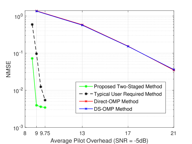
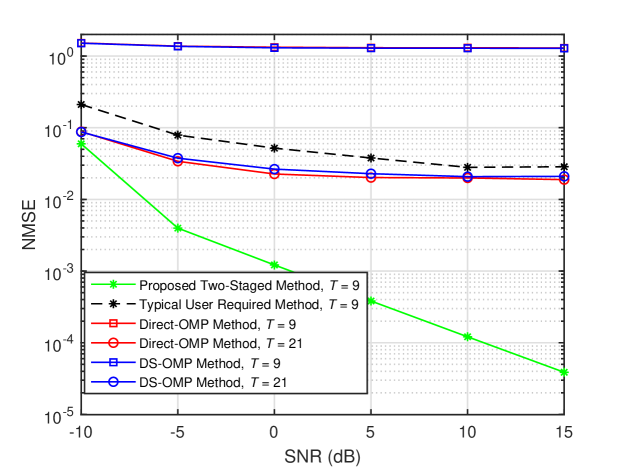
Fig. 2 displays the NMSE performance of different methods versus SNR. We observe the estimation performances of all the methods are unacceptable under low SNR case, e.g., the NMSEs are larger than 10110^{-1} with SNR = 10-10 dB. Fortunately, their NMSEs are improved with the growth of the SNR. In particular, the NMSE of the Proposed Two-Staged Method decreases drastically with the SNR. By contrast, due to the shortage of measurements, the estimation accuracy of the three benchmark methods improves slightly and reaches saturation at relatively high SNR. The gap between the proposed method and the three benchmark methods becomes noticeably larger.

Refer to caption
Figure 2: NMSEs vs. SNR for the ULA-type RIS case when N=100N=100, M=100M=100, K=16K=16.

V Conclusions

In this paper, we proposed a novel two-stage based uplink channel estimation strategy for an RIS-aided multi-user mmWave communication system. In Stage I, all users jointly constructed the ambiguous common RIS-BS channel so as to obtain multi-user diversity gain. In Stage II, each user independently estimated their own ambiguous specific user-RIS channel with reduced pilot overhead. Additionally, theoretical overall minimum number of pilots required by the proposed strategy was analyzed. Simulation results validated that the proposed method outperforms other existing algorithms in terms of pilot overhead.

References

  • [1] C. Pan, H. Ren, K. Wang et al., “Reconfigurable intelligent surfaces for 6G systems: Principles, applications, and research directions,” IEEE Commun. Mag., vol. 59, no. 6, pp. 14–20, Jun. 2021.
  • [2] M. Di Renzo, A. Zappone, M. Debbah et al., “Smart radio environments empowered by reconfigurable intelligent surfaces: How it works, state of research, and the road ahead,” IEEE J. Sel. Areas Commun., vol. 38, no. 11, pp. 2450–2525, Nov. 2020.
  • [3] C. Pan, H. Ren, K. Wang et al., “Intelligent reflecting surface aided MIMO broadcasting for simultaneous wireless information and power transfer,” IEEE J. Sel. Areas Commun., vol. 38, no. 8, pp. 1719–1734, Aug. 2020.
  • [4] A. L. Swindlehurst, G. Zhou, R. Liu, C. Pan, and M. Li, “Channel estimation with reconfigurable intelligent surfaces–a general framework,” Proc. IEEE, early access, pp. 1–27, 2022.
  • [5] X. Wei, D. Shen, and L. Dai, “Channel estimation for RIS assisted wireless communications: Part II - an improved solution based on double-structured sparsity,” IEEE Commun. Lett., vol. 25, no. 5, pp. 1403–1407, May 2021.
  • [6] Z. Wang, L. Liu, and S. Cui, “Channel estimation for intelligent reflecting surface assisted multiuser communications: Framework, algorithms, and analysis,” IEEE Trans. Wireless Commun., vol. 19, no. 10, pp. 6607–6620, Oct. 2020.
  • [7] Y. Wei, M.-M. Zhao, M.-J. Zhao, and Y. Cai, “Channel estimation for IRS-aided multiuser communications with reduced error propagation,” IEEE Trans. Wireless Commun, vol. 21, no. 4, pp. 2725–2741, Oct. 2022.
  • [8] G. Zhou, C. Pan, H. Ren, P. Popovski, and A. L. Swindlehurst, “Channel estimation for RIS-aided multiuser millimeter-wave systems,” IEEE Trans. Signal Process., vol. 70, pp. 1478–1492, Mar. 2022.
  • [9] T. Lin, X. Yu, Y. Zhu, and R. Schober, “Channel estimation for IRS-assisted millimeter-wave MIMO systems: Sparsity-inspired approaches,” IEEE Trans. Commun., vol. 70, no. 6, pp. 4078–4092, Apr. 2022.
  • [10] P. Wang, J. Fang, H. Duan, and H. Li, “Compressed channel estimation for intelligent reflecting surface-assisted millimeter wave systems,” IEEE Signal Process. Lett., vol. 27, pp. 905–909, May 2020.