Energy-Efficient UAV-Mounted RIS Assisted Mobile Edge Computing
Abstract
Unmanned aerial vehicle (UAV) and reconfigurable intelligent surface (RIS) have been recently applied in the field of mobile edge computing (MEC) to improve the data exchange environment by proactively changing the wireless channels through maneuverable location deployment and intelligent signals reflection, respectively. Nevertheless, they may suffer from inherent limitations in practical scenarios. UAV-mounted RIS (U-RIS), as a promising integrated approach, can combine the advantages of UAV and RIS to break the limit. Inspired by this, we consider a novel U-RIS assisted MEC system, where a U-RIS is deployed to assist the communication between the ground users and an MEC server. The joint UAV trajectory, RIS passive beamforming and MEC resource allocation design is developed to maximize the energy efficiency (EE) of the system. To tackle the intractable non-convex problem, we divide it into two subproblems and solve them iteratively based on successive convex approximation (SCA) and the Dinkelbach method. Finally we obtain a high-performance suboptimal solution. Simulation results show that the proposed algorithm significantly improves the energy efficiency of the MEC system.
Index Terms:
Energy efficiency, UAV-mounted RIS, mobile edge computing, trajectory design, passive beamformingI Introduction
Driven by the popularity of mobile users and unprecedented increase of network traffic in the Internet of Things (IoT)[1], mobile edge computing (MEC) is regarded as an emerging paradigm that executes computation-intensive and latency-critical tasks at the network edges to meet the demands of the resource-constrained mobile devices[2]. However, imperfect offloading links limit the exploitation of MEC. For example, since the direct offloading link may be blocked with a high probability, the poor channel condition forces the users to process their tasks locally to maintain strict lantency requirements, which is unbearable for resource-limited mobile users. Hence, many works aim to improve the channel quality of MEC systems. Owing to the line-of-sight (LoS) transmission and flexible maneuverability, it is promising to enable unmanned aerial vehicles (UAVs) to carry an MEC server (UAV-carried server) for providing data exchange and computing services[3], [4]. Particularly,[3] proposed a joint resource allocation and UAV trajectory optimization scheme to maximize the energy efficiency (EE), and [4] deployed multiple ground servers and a UAV server in a cooperative manner to provide high-quality edge computing. As another way to improve the channel quality, reconfigurable intelligent surface (RIS) is a cost-effective and energy-efficient equipment that can be manipulated to alter the incident signal. It is considered as a win-win strategy to integrate RIS into MEC systems[5]. The work in[6] reported that up to 20 of the computing latency can be eliminated with the existence of RIS.
Unfortunately, both UAV and RIS face their respective deficiencies, e.g., finite endurance and limited coverage. To overcome these issues, mounting RIS on UAV (named UAV-mounted RIS, U-RIS) to support terrestrial communication[7] is a promising approach. Compared with the UAV-carried server scheme, the U-RIS structure can be regarded as an effective upgrade to the traditional land server-based MEC system, without the need for routing change and system reconstruction. Furthermore, a RIS is usually much lighter than an MEC server[8], leading to a lower UAV’s on-board energy consumption. Besides, in the RIS-assisted MEC scheme, the RIS coated on the facade of buildings is only effective for the users in the front space. By contrast, on the aerial platform of UAV, RIS can enjoy a better full-angle panoramic beamforming capability towards users.
For the above reasons, we consider a U-RIS assisted MEC system. Due to complex practical environments, the link between the ground users and the MEC server may be blocked. A U-RIS is dispatched to assist the users in offloading their tasks where the signals of users are reflected to the ground MEC server via the U-RIS. To balance the total processing bits and the energy consumption, our goal is to maximize the energy efficiency of the propposed system by jointly optimizing the UAV trajectory, passive beamforming, and resource allocation. The formulated problem is a mixed-integer non-linear fractional programming problem. By leveraging the successive convex approximation (SCA) technique and the Dinkelbach method, we develop an efficient algorithm to obtain a suboptimal solution. Numerical results demonstrate that the proposed algorithm achieves a substantial EE improvement of the MEC systems over other baseline schemes, and significant trade-off is made in the flight trajectory optimization.
II System Model and Problem Formulation
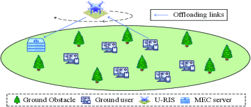
The U-RIS assisted MEC network is shown in Fig. 1, consisting of users, an MEC server and a RIS that is mounted on a UAV. The U-RIS is deployed to assist the MEC server in providing edge computing service to the ground users. Denote by the set of users. Without loss of generality, the time span T is divided into N time slots with size of , which is indexed by .
It is assumed that all the nodes in the MEC system are located in the three-dimensional (3D) Cartesian coordinate system, and the horizontal coordinates of the MEC server as well as user k can be denoted by and , respectively. We assume that the U-RIS flies at a fixed altitude H and its position remains unchanged within each time slot. Thus, the horizontal trajectory of the U-RIS during the time span T can be denoted by the sequence , satisfying the following mechanical and flight constraints
| (1a) | |||
| (1b) | |||
| (1c) | |||
where and are the UAV’s maximum speed and acceleration, and denote the initial and final horizontal positions of the U-RIS, and is the horizontal flight range of the U-RIS. The last part of (1c) is owing to that the U-RIS should be practically tethered to a fixed ground station for dependable power supply and stable control[7].
II-A Communication Model
We assume that the MEC server and the ground users are equipped with a single omni-directional antenna for each. The U-RIS is equipped with reflective elements, forming an uniform rectangular array (URA). Let denote the phase of the th reflecting element in time slot , and be the diagonal phase array for the RIS in the th time slot.
We assume the links from the ground users to the U-RIS (G-U link) and from the U-RIS to the MEC server (U-S link) follow a quasi-static block fading LoS model[9]. The link between user and the U-RIS in the th time slot, denoted by , can be expressed as[10]
| (2) |
where
, where is the channel gain with a distance of 1 meter, is the distance between user and the U-RIS in time slot , is the pass loss exponent due to the LoS transmission. Moreover, and denote respectively the azimuth and elevation angles of user at time slot , is the wavelength of carrier and is the antenna separation. The U-S link in time slot , denoted as , can be modeled similarly.
We consider the TDMA scheme for the task offloading, which means that only one user communicates with the server in a time slot. Denote as the user scheduling variable. If user is chosen to be served by the U-RIS in the th time slot, we have =1, yielding the following constraints
| (3) |
Therefore, the achievable rate of user in the th time slot can be expressed as
| (4) |
where the parameter , and denote the channel bandwidth, fixed transmission power of users and the noise variance respectively. Thus, the average achievable rate of user during the computing cycle is given by .
II-B Computation Model
To exploit the full granularity in task partitioning and computing resources, we consider the way of partial offloading[11]. Specifically, the computing tasks can be divided into arbitrary sizes, and part of the tasks can be offloaded to the server, while the remaining tasks are processed locally. Denote the total offloading and local computing tasks of user over time slots as and in bits, respectively. Let be the maximum tolerable latency of user . Then we have
| (5) |
where denotes the number of CPU cycles required for processing one bit of user , is user ’s fixed CPU frequency, and is the allocated CPU frequency to compute the task of user at the MEC server. This constraint is based on two assumptions: First, the edge computing for user does not start until bits are offloaded; second, using dynamic voltage and frequency scaling (DVFS) technique, the server can dynamically allocate its resources.
II-C Energy Consumption Model
In the MEC system, the total energy consumption over time slots is composed of three main parts: the energy consumed by the users for offloading and local computing, by the server for computing, and by the U-RIS flight. The energy consumption for user can be formulated as111Actually, the offloading duration is , but is mainly occupied by and the energy used for transmission is relatively small[3]. So we can replace it with to simplify the model without performance loss.
| (6) |
where is the switched capacitance coefficient for the users [12]. Denote as the coefficient for the server, and the energy consumption of the server for computing user ’s tasks is
| (7) |
We adopt the novel energy consumption model for rotary-wing UAVs proposed in [13], which takes the practical thrust-to-weight ratio into consideration, i.e.,
| (8) |
where is a factor of the energy consumption for the U-RIS flight during the th time slot, and with . Here is the total mass of the UAV and the RIS; , , , , , and , are all mechanical coefficients; see [13] for more details.
Generally speaking, the energy consumption of the U-RIS is much larger than that of the users and the server, but the latter two are crucial in real MEC networks. Hence, we introduce a weight factor for the sum of , with the weighted total energy consumption formulated as
| (9) |
II-D Problem Formulation
In this letter, the definition of the energy efficiency is the ratio of total computed tasks in bits to the weighted total energy consumption of the system. Our main objective is to maximize the energy efficiency of the MEC system by jointly optimizing the user scheduling , the phase-shift matrix of the U-RIS , the U-RIS’s trajectory , the overall computed tasks in bits and the CPU frequency allocation for different users of server . The problem can be formulated as
| (10a) | |||
| (10b) | |||
| (10c) | |||
| (10d) | |||
| (10e) | |||
where (10b) denotes the phase constraint of the U-RIS, (10c) indicates that there is a threshold for the minimum offloading tasks for user , and (10d) means that the total server’s CPU frequency is limited by the maximum value . Problem (10) is a challenging mixed-integer non-linear fractional programming problem where the objective function and the constraints (3) and (5) are not jointly convex w.r.t. the optimization variables. In the next section, we propose an iterative algorithm to efficiently obtain a suboptimal solution.
III Proposed Algorithm
In this section, we propose an iterative algorithm based on the SCA to obtain a solution to problem (10). Specifically, we divide (10) into two subproblems, i.e., the joint optimization of and as well as that of , and . We solve the two subproblems iteratively until convergence.
III-A Optimizing and for Given , and
To handle the coupled variables, we first consider the design of the phase shift . If the U-RIS chooses to serve user in time slot , i.e., , the achievable rate is denoted as
| (11) |
where . Clearly, if the multipath signals superimpose coherently, the rate can reach the maximum. This means that the U-RIS can play an phase alignment role by setting , yielding the following maximum achievable rate
| (12) |
where . After determining the value of , we relax the integer constraint (3) into a linear form, and obtain the following standard LP problem for the optimization of :
| (13a) | |||
| (13b) | |||
| (13c) | |||
where . This problem can be solved by the CVX solver. Finally, are reconstructed as binary variables via rounding.
III-B Optimizing , and for Given and
For any given and , problem (10) can be recast as
| (14a) | |||
| (14b) | |||
Note that problem (14) is difficult to solve due to the non-convex objective function and constraint (5). To obtain an approximate solution, we first consider convexifying the constraint. By introducing the slack variables , , where , , and the auxiliary variable , constraint (5) can be transformed into
| (15a) | |||
| (15b) | |||
| (15c) | |||
where . Since and can be increased to reduce the objective value, the constraints of and must hold with equality at the optimal solution to problem (14); hence, constraint (5) can be equivalently relaxed into (15) without loss of optimality. Note that is convex with respect to and , so we apply the first-order Taylor expansion of at the given point , in the th iteration to convert the non-convex constraint (15a) to a convex form as follows
| (16) |
where
and .
We next deal with the non-convex objective function. Note that and are the two non-convex terms in the denominator of the objective function. To tackle the non-convexity of , we successively apply the inequalities and for the non-convex term and in , respectively. Finally we get a convex upper bound of , expressed as
| (17) |
To handle the non-convexity of , similarly we introduce the slack variable satisfying . By inequality transformation and applying first-order Taylor expansion at given point in the th iteration, we have
| (18) |
Therefore, problem (14) can be approximated as
| (19c) | |||
| (19d) | |||
| (19e) | |||
| (19f) | |||
This problem is quasi-convex because the objective function consists of a linear numerator as well as a convex denominator and all constraints are convex. Therefore, it can be efficiently solved by existing fractional programming methods, such as the Dinkelbach algorithm.
III-C Overall Algorithm
Based on the solutions obtained in the previous two subsections, the designed overall algorithm for problem (10) is summarized in Algorithm 1. The complexity of the proposed algorithm is . In general, Algorithm 1 yields a lower bound of the original problem, and its performance in improving system energy efficiency is verified in Section IV.
IV Numerical Results
In this section, we analyze the effectiveness of the proposed algorithm with numerical results. The objective of the proposed algorithm is to maximize the total energy efficiency of the whole MEC system (denoted as max total EE), at the expense of the quality of task processing for some individual users. When each user has urgent tasks and it is important to ensure high energy efficiency and fairness, we also propose an algorithm to maximize the minimum energy efficiency over all users (denoted as max min EE) by replacing the objective function in (10) with where . This problem can be solved similarly, and the algorithm will not be described due to space limitations.
Besides, we set two baseline algorithms aiming to maximize the system total energy efficiency for comparison: 1) Heuristic-traj means that the U-RIS traverses each user node along the pre-defined shortest route at a constant speed, with optimized and ; 2) UAV-Server means that a UAV-carried server is used to provide edge computing, with optimized and . This is the traditional practice of the UAV-assisted MEC system. Compared with the proposed algorithm, UAV-Server will not lead to a cascade channel but increase the flight burden. Besides, the maximal CPU frequency of the MEC server in the UAV-Server scheme is lower than that of the land-based MEC server in practice. Simulation parameters are set as 1 MHz, dBm, dB, , m, m/s, , s, m, m, m, m, , , MHz, . , , , , , for , the mass of UAV, RIS and MEC server are 2 kg, 2 kg and 20 kg, respectively.
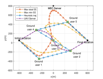
Fig. 4 shows the U-RIS or UAV trajectories of the various algorithms ( s), all of which are significantly different. We observe that in the proposed max total EE algorithm, the U-RIS first flies towards user 1, and then approaches the server along the trajectory colse to user 3. After that, the U-RIS decelerates and finally reaches the endpoint. Flying along this trajectory achieves the highest total energy efficiency because it strikes the best balance between the G-U and U-S links, i.e., an effective trade-off is made between “near the server to enjoy high-quality channel with all user”, and “poor quality channel during flying towards the remote server”. In this algorithm, the U-RIS only meets the minimum demand of the poor users, while serving the users with high channel quality to increase the total processed tasks. On the contrary, the U-RIS in max min EE needs to take account of each user, especially users 1 and 2, whose long-distance from the server leads to greater path loss. For the Heuristic-traj algorithm, the U-RIS flies along a straight-line route through all users, which consumes a lot of energy due to the frequent speed and direction changes. Besides, as for the UAV-Server algorithm, compromises are made between the flight energy consumption and the channel quality. The UAV in this scheme flies to focusing on the service for users 2, 3 and 4 with fewer detours.
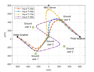
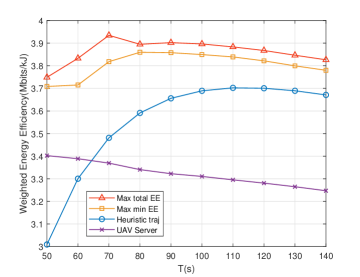
Fig. 4 and Fig. 4 illustrate the trajectories of the max total EE algorithm and the total EE of various algorithms versus , respectively. Different from the characteristics of a general UAV-assisted system, users in the MEC system have their own tolerated latency. Hence the excessive flight time will rather lead to a decrease of the EE (as shown in Fig. 4 when s), so we set a moderate period s to perform the trajectory analysis. In Fig. 4, the trajectory of s has a visible difference from that of other , because it has just achieved the trade-off mentioned above, which is also the reason why the EE peaks at 70 s in the EE curve of max total EE algorithm in Fig. 4. This means that 70 s is the optimal time span of this system. As the period grows longer ( s), it is necessary to make full use of the latency of each user to offload more tasks. Hence the U-RIS adopts a strategy similar to max min EE, and the EE of these two algorithms get close when s. In Fig. 4, it is observed that the proposed max total EE algorithm has a considerable performance gain compared to the baseline algorithms. It is worth noting that the Heuristic-traj algorithm can be treated as a lower bound of the EE for the preliminary system design. Besides, due to the high flight energy consumption of the UAV-Server scheme, the EE under this algorithm shows a downward trend even in the early stage.
V Conclusions
In this paper, the UAV-mounted RIS technique has been introduced to enhance the user offloading link, thereby further improving the performance of the MEC system. We proposed a joint RIS passive beamforming, UAV trajectory and MEC resource allocation optimization algorithm to maximize the EE and obtained a high-quality suboptimal solution. Numerical results gave evidence of the significant benefits that the U-RIS can provide in the MEC system.
References
- [1] M. R. Palattella, M. Dohler, A. Grieco, G. Rizzo, J. Torsner, T. Engel, and L. Ladid, “Internet of things in the 5G era: Enablers, architecture, and business models,” IEEE J. Sel. Areas Commun., vol. 34, no. 3, pp. 510–527, 2016.
- [2] Y. Mao, C. You, J. Zhang, K. Huang, and K. B. Letaief, “A survey on mobile edge computing: The communication perspective,” IEEE Commun. Surv. Tut., vol. 19, no. 4, pp. 2322–2358, 2017.
- [3] M. Li, N. Cheng, J. Gao, Y. Wang, L. Zhao, and X. Shen, “Energy-efficient UAV-assisted mobile edge computing: Resource allocation and trajectory optimization,” IEEE Trans. Veh. Technol., vol. 69, no. 3, pp. 3424–3438, 2020.
- [4] Y. Xu, T. Zhang, Y. Liu, D. Yang, L. Xiao, and M. Tao, “UAV-assisted MEC networks with aerial and ground cooperation,” IEEE Trans. Wireless Commun., vol. 20, no. 12, pp. 7712–7727, 2021.
- [5] M. Mukherjee, V. Kumar, M. Guo, D. B. da Costa, E. Basar, and Z. Ding, “The interplay of reconfigurable intelligent surfaces and mobile edge computing in future wireless networks: A win-win strategy to 6G,” arXiv preprint arXiv:2106.11784, 2021.
- [6] T. Bai, C. Pan, Y. Deng, M. Elkashlan, A. Nallanathan, and L. Hanzo, “Latency minimization for intelligent reflecting surface aided mobile edge computing,” IEEE J. Sel. Areas Commun., vol. 38, no. 11, pp. 2666–2682, 2020.
- [7] C. You, Z. Kang, Y. Zeng, and R. Zhang, “Enabling smart reflection in integrated air-ground wireless network: IRS meets UAV,” IEEE Wireless Commun., vol. 28, no. 6, pp. 138–144, 2021.
- [8] L. Dai, B. Wang, M. Wang, X. Yang, J. Tan, S. Bi, S. Xu, F. Yang, Z. Chen, M. Di Renzo et al., “Reconfigurable intelligent surface-based wireless communications: Antenna design, prototyping, and experimental results,” IEEE Access, vol. 8, pp. 45 913–45 923, 2020.
- [9] Y. Zeng and R. Zhang, “Energy-efficient UAV communication with trajectory optimization,” IEEE Trans. Wireless Commun., vol. 16, no. 6, pp. 3747–3760, 2017.
- [10] S. Li, B. Duo, M. Di Renzo, M. Tao, and X. Yuan, “Robust secure UAV communications with the aid of reconfigurable intelligent surfaces,” IEEE Trans. Wireless Commun., 2021.
- [11] S. Jeong, O. Simeone, and J. Kang, “Mobile edge computing via a UAV-mounted cloudlet: Optimization of bit allocation and path planning,” IEEE Trans. Veh. Technol., vol. 67, no. 3, pp. 2049–2063, 2017.
- [12] H. Mei, K. Wang, D. Zhou, and K. Yang, “Joint trajectory-task-cache optimization in UAV-enabled mobile edge networks for cyber-physical system,” IEEE Access, vol. 7, pp. 156 476–156 488, 2019.
- [13] X. Dai, B. Duo, X. Yuan, and W. Tang, “Energy-efficient UAV communications: A generalised propulsion energy consumption model,” arXiv preprint arXiv:2202.08486, 2022.