Further author information:
C.P.:
E-mail: [email protected]
End-to-end simulations of a near-infrared pyramid sensor on Keck II
Abstract
The future upgrade of Keck II telescope’s adaptive optics system will include a pyramid wavefront sensor working in the near-infrared (J and H band). It will benefit from the recently developed avalanche photodiode arrays, specifically the SAPHIRA (Selex) array, which provides a low noise ( 1 e- at high frame rates). The system will either work with a natural guide star (NGS) in a single conjugated adaptive optics system, or in a laser guide star (LGS) mode. In this case, the pyramid would be used as a low-order sensor only. We report on a study of the pyramid sensor’s performance via end-to-end simulations, applied to Keck’s specific case. We present the expected Strehl ratio with optimized configurations in NGS mode, and the expected residual on low orders in LGS mode. In the latter case, we also compare the pyramid to LIFT, a focal-plane sensor, demonstrating the ability of LIFT to provide a gain of about 2 magnitudes for low-order sensing.
keywords:
Adaptive optics, Wavefront sensing, Infrared, Keck, Pyramid, LIFT1 INTRODUCTION
The future upgrade of Keck II telescope’s Adaptive Optics (AO) system [1] will include a pyramid wavefront sensor [2] working in the near-infrared (J and H band)[3]. The main goal of this upgrade is to perform direct imaging and slit spectroscopy of exoplanets around M dwarfs. The flux from these stars is very faint at optical wavelengths, but sufficient in the near-infrared to use as NGSs in a single conjugated AO system, given the adequate detector technology. The recently developed avalanche photodiode arrays, such as the SAPHIRA (Selex), provide a low noise ( 1 e- at high frame rates) and are thus suitable for this application [4]. In addition to the NGS mode, the system will also provide a LGS mode. In this case, the pyramid would be used as a low-order sensor only. We report on a study of the pyramid sensor’s performance via end-to-end simulations made with PASSATA [5]. After a quick summary of the simulation parameters (section 2), we present the expected Strehl ratio in NGS mode (section 3), and the expected residual on low orders in LGS mode (section 4). In the latter case, the pyramid will not benefit from a hardware rebinning of pixels, and thus will not be in a fully optimized configuration. For this reason, we also compare the pyramid to LIFT [6], a focal-plane sensor, that could provide a better low-order estimation at low flux.
2 Simulations parameters
We list in Table 1 the simulation parameters used for the different cases of this study. The chosen values for the parameters that are optimized (modulation, frequency, control gain…) are given in each specific case, and we only state here the explored ranges of values. The wavefront modes (turbulent Karhunen-Loève and Zernike) are considered to be perfectly reproduced by the deformable mirror (DM). In all cases, the correction is made with an integrator command, and the delay depends on the frequency, with the following rules (taken from ERIS simulations experience [7]):
-
•
: 3 frames delay
-
•
: 2 frames delay
-
•
: 1 frame delay
| Parameter | NGS mode | LGS mode | ||
|---|---|---|---|---|
| 2020 | 3232 | 2020 | 3232 | |
| Sensing band | 1.5 - 1.8 (H band) | |||
| Pupil mask | Keck primary on 512 pixels | Keck primary on 256 pixels | ||
| Mode basis | 250 KL modes | 245 KL modes + 5 first Zernike | ||
| Total transmission (including QE) | 0.3 | |||
| Sky background in H | 14 mag/arcsec2 | |||
| Seeing | 0.63” | |||
| Layers’ altitudes (km) | 0, 500, 1000, 2000, 4000, 8000, 16000 | |||
| profile (normalized in energy) | 0.517, 0.119, 0.063, 0.061, 0.105, 0.081, 0.054 | |||
| Mean wind speed | 9.5 m/s | |||
| Zenith angle | 30° | |||
| Subaperture size | 0.5625 m | 0.35 m | 0.5625 m | 0.35 m |
| APD gain | 30 | |||
| Excess noise factor | 1.4 | |||
| Read-out noise | 0.1 or 1 e- | 1 e- | 0.8 e- | 1 e- |
| Dark current | 0 or 100 e-/s | 20 e-/s | 100 e-/s | 20 e-/s |
| Frequency range | 300-1000 Hz | 200-1000 Hz | ||
| Control gain range | 0.1-0.6 | LIFT: 0.1-0.6 | LIFT: 0.1-0.6 | |
| Pyramid: 0.15-10 | Pyramid:0.25-5 | |||
| Pyramid modulation radius range | 1-3 | 1-2 | 0-2 | |
| FoV | 1” | |||
| Additional HO residual (non corrected) | 60 nm | 0 nm | 60 nm | |
To these parameters, we add the following precisions for the LGS mode:
-
•
High-order loop parameters:
-
–
Sensor: SH 2020 with quad-cells estimating 250 modes.
-
–
LGS = high flux point source at finite distance.
-
–
Tip/tilt filtered and replaced by a residual jitter of 106 mas rms + turbulent tip/tilt.
-
–
Control gain: 0.3.
-
–
-
•
Focus loop (only in 3232 case):
-
–
Correction frequency: 10 Hz.
-
–
Input: focus residual from high-order control + sinusoid of period 5 seconds and amplitude 100 nm (80 nm rms).
-
–
Control gain range: 0.1-1 for LIFT, 0.1-4 for the pyramid.
-
–
Finally, for consistency with the error budget used in a previous study [3], we add a constant error of 165 nm rms to the residual in NGS mode, representing miscellaneous errors from undetermined sources.
3 NGS mode
In this section, we study the performance of the pyramid, in terms of Strehl ratio, for different pupil samplings. We first considered a pupil sampling of 2020 subapertures, in agreement with the current DM’s number of actuators. However, the DM should be upgraded to a MEMS 3232. We thus study in a second step the impact of increasing the pupil sampling to 3232, or to 4040 for robustness reasons.
3.1 Pyramid 2020
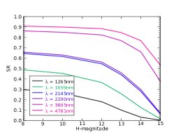
We present here the results of the simulations with a pyramid 2020 in NGS mode (Fig. 1(c)). The parameters, listed in Table 2, are optimized in the ranges described previously to get the highest Strehl ratio. This optimization is simply made by running simulations going through the whole set of parameters and selecting the best one.
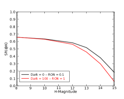
As we lacked information on the detector’s noise, we considered two cases: low noise (no dark current, read-out noise = 0.1 e-) and high noise (dark current = 100 e-/s, read-out noise = 1 e-). The difference between those two cases is not very significant (0.5 magnitude at faint end).
| Magnitude | 8 | 10 | 12 | 13 | 14 | 15 |
| Frequency (Hz) | 1000/1000 | 1000/1000 | 1000/600 | 1000/500 | 600/300 | 600/300 |
| Number of modes | 250/250 | 250/250 | 170/152 | 135/104 | 65/54 | 44/14 |
| Gain | 0.3/0.3 | 0.2/0.2 | 0.15/0.25 | 0.15/0.3 | 0.3/0.55 | 0.3/0.6 |
| Modulation radius () | 1.5 | 1.5 | 1.5 | 1.5 | 1.5 | 2 |
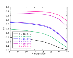
Overall, what we observe on the optimization of the parameters when we are going towards lower fluxes is:
-
•
Decrease in frequency: to collect more flux and reduce the noise error.
-
•
Increase the gain: we cannot remove the background in pyramid images, it is thus taken into account in the normalization when computing the slopes. In the end, the slopes are proportional to the ratio star flux/background, which decreases with respect to the magnitude. A higher gain is needed to compensate that effect. The increase in gain is also needed at lower frequencies, as the correction is done less often.
-
•
Increase in modulation: at low flux, the noise error makes the pyramid work in non-linear regime. The modulation reduces the non-linearity error, at the price of a lower sensitivity (hence greater noise error). A trade-off is made between those two errors to reach the lowest overall error. At high flux, using a high modulation lowers the non-linearity error.
-
•
Decrease the number of modes: estimating less modes improves the noise propagation behavior at low orders.
These results are consistent with the ones presented in an earlier study[3], with a difference of only a few percents of Strehl ratio in K band.
3.2 Impact of a finer pupil sampling
Having a finer pupil sampling allows us to estimate more modes at high flux, but lowers the signal-to-noise ratio (SNR) at low flux. We consider here only the impact at low flux, as it corresponds to more practical cases and is more critical for the system design.
We simulated two different pupil samplings: 3232 and 4040 (in that case, only the subaperture size from Table 1 is changed). The first one matches the MEMS mirror sampling, while the second would help calibrate misregistration errors and thus gain in robustness.
The performance and optimized parameters at magnitude 14 are given in Table 3, for a dark current of 20 e-/s and a read-out noise of 1 e-. The performance for the high noise case of the pyramid 2020 is recalled for reference. It should be noted that the dark current does not have a significant impact here, the results can thus be fairly compared.
| Frequency (Hz) | Number of modes | Gain | Modulation radius () | Strehl ratio (K) | |
|---|---|---|---|---|---|
| 2020 | 600 | 65 | 0.3 | 1.5 | 29.8% |
| 3232 | 200 | 65 | 0.75 | 1.5 | 26.7% |
| 4040 | 200 | 65 | 0.75 | 1.5 | 25.1% |
The finer pupil sampling does not have a strong impact on performance: the loss of Strehl in Ks is 3% for the 3232 and 5% for the 4040. Hence, it seems a reasonable choice to go towards a 4040 sampling, making the system more reliable without a significant loss of performance at low flux.
4 LGS mode
The goal of this section is to assess the achievable residual on tip/tilt and focus in LGS mode, for a NGS on axis or at 15” off axis. We compare the pyramid to LIFT, in order to evaluate the gain of having a focal-plane sensor for this low-order estimation. Indeed, as we cannot do a hardware rebin of pixels on the camera, the pyramid would still utilise a fine sampling and would thus have poorer noise propagation properties for low-order estimation than with a coarse sampling.
As in the previous section, we first considered a pyramid with 2020, and then checked the impact of a finer sampling. For LIFT, the only design parameter that will have an impact on the performance is the pixel scale. We consider here a pixel of 15 or 30 mas, corresponding respectively to a Nyquist and a Nyquist/2 sampling in H band.
4.1 Pyramid 2020
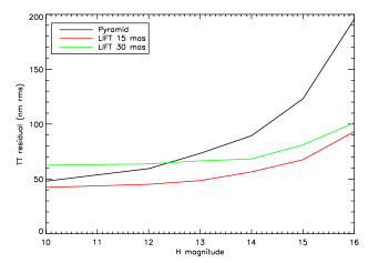
In this part, we only evaluate the residual on tip/tilt, as it is the most important feature of the low-order sensor. The focus estimation will be included in the next section. For practical reasons, the number of reconstructed modes for the pyramid is either 2 (lowest noise error) or 250 (lowest aliasing error).
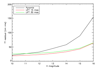
We list in Tables 4, 5 and 6 the optimized parameters for LIFT and the pyramid in each case, as well as the residual on tip/tilt. The residuals obtained with LIFT and the pyramid are compared in Fig. 2(b). We find that LIFT provides a gain of up to 2 magnitudes over the pyramid, either on axis or off axis.
The behavior of the optimized parameters for the pyramid is as described in section 3.1. In particular, we can notice an increase in modulation at high flux when going off-axis: this is due to the increase in amplitude of high-order modes, for which the linearity must be improved. The flux is sufficiently high in that case to use a strong modulation without a significant impact on noise error.
As concerns LIFT’s sampling, the pixel of 30 mas benefits from better noise propagation properties (better SNR/pixel), but does not provide any significant improvement of the performance. On the contrary, it is less efficient off axis, or at high flux in general. Indeed, the signal from high orders, normally far from the spot center, gets more easily mixed with the low orders signal, which is within the spot center. This aliasing error is visible at high flux, where the noise error is negligible, and gets higher when going off axis, where the Strehl ratio is lower. The overall aliasing + noise error is in the end always better with the 15 mas pixel for the considered magnitudes.
| Magnitude | 10 | 12 | 13 | 14 | 15 | 16 |
|---|---|---|---|---|---|---|
| Frequency (Hz) | 1000/1000 | 1000/1000 | 1000/1000 | 1000/1000 | 200/200 | 200/200 |
| Number of modes | 250/250 | 250/250 | 2/250 | 2/2 | 2/2 | 2/2 |
| Gain | 0.5/0.25 | 0.5/0.65 | 0.75/0.65 | 1/1 | 3.5/3.5 | 5/5 |
| Modulation radius () | 0/2 | 0/0 | 0/0 | 0/0 | 0/0 | 0/1 |
| TT residual (nm rms) | 21.4/48 | 32.3/59.4 | 44.6/73.3 | 57.8/89.4 | 88.6/123 | 153.7/195.6 |
| Magnitude | 10 | 12 | 13 | 14 | 15 | 16 |
|---|---|---|---|---|---|---|
| Frequency (Hz) | 1000/1000 | 1000/1000 | 1000/333 | 333/333 | 333/200 | 200/200 |
| Gain | 0.3/0.3 | 0.3/0.3 | 0.2/0.5 | 0.4/0.5 | 0.4/0.4 | 0.4/0.3 |
| TT residual (nm rms) | 18.9/42.3 | 23.2/45.1 | 27.3/48.5 | 33.1/56.4 | 42.9/67.5 | 63.5/93.2 |
| Magnitude | 10 | 12 | 13 | 14 | 15 | 16 |
|---|---|---|---|---|---|---|
| Frequency (Hz) | 1000/1000 | 1000/1000 | 1000/1000 | 333/1000 | 333/500 | 200/333 |
| Gain | 0.4/0.3 | 0.3/0.2 | 0.2/0.2 | 0.5/0.2 | 0.4/0.2 | 0.4/0.3 |
| TT residual (nm rms) | 25.7/62.5 | 28.5/63.7 | 31.5/66.5 | 37.6/68.3 | 45.6/81.1 | 64.5/101.2 |
4.2 Finer pupil sampling
We now check the impact of having a finer-sampled pyramid on the performance at magnitude 14. We also verify that we have a correct estimation of focus on both sensors, and we study the possibility of having 10 mas pixels on LIFT (for design simplicity reasons).
The parameters and results are given in Table 7, for an optimization on tip/tilt correction only (the focus is then added with the same loop parameters).
On axis, there is a clear advantage using LIFT for tip/tilt estimation, with a factor 2 in rms residual. The estimation of focus does not affect the estimation of tip/tilt, whatever the sensor, and LIFT has a slight advantage on this mode as well (factor 1.4).
Off axis, we still have a better estimation of tip/tilt with LIFT, but with less difference (factor 1.4 at best). LIFT’s performance is actually weakly dependent on the frequency: at 1000 Hz, the tip/tilt residual is increased by approximately 5 nm for the 15 mas and 10 mas pixels. The focus correction is similar in all cases, and the tip/tilt estimation is always affected. This might be the result of the sensors getting less and less linear when lowering the Strehl ratio (aliasing error discussed in the previous section). The effect seems stronger on LIFT at fine samplings (15 and 10 mas), but for these cases, as well as the pyramid, it is equivalent to adding an error of approximately 30-35 nm rms. For LIFT with 30 mas pixels, this error is lower, around 20 nm rms. This might be due to the fact that the tip/tilt estimation alone was already affected by non-linear effects.
| LIFT 30 mas | LIFT 15 mas | LIFT 10 mas | Pyramid | |
| Frequency (Hz) | 333/1000 | 333/200 | 333/333 | 333/333 |
| Modulation radius () | 0/0 | |||
| Gain | 0.4/0.1 | 0.4/0.5 | 0.4/0.3 | 4/4 |
| TT residual (nm rms) | 39.3/80.5 | 34.3/67.5 | 34.7/69.8 | 68.9/95.9 |
| TT residual (with focus) | 36.2/82.7 | 33.6/75.9 | 34.8/77.7 | 69.3/100 |
| Gain on focus | 0.6/0.4 | 0.5/0.4 | 0.7/0.3 | 2/1.5 |
| Focus residual (nm rms) | 37/52.9 | 38.4/53.1 | 35.9/53.2 | 50.5/50.8 |
5 CONCLUSION
We have studied the performance of a near-infrared pyramid for the next generation AO of Keck II, which will include a classical AO mode (NGS mode) and a LGS mode. In NGS mode, the pyramid will provide a Strehl ratio in K band of 37% at magnitude H = 14 and 80% at high flux (2020 configuration). The latter can be increased with a finer pupil sampling (3232, or 4040) and a higher degree of correction (i. e. 3232 DM), without degrading significantly the performance at low flux. The 4040 sampling would also provide more robustness to errors such as misregistration. In LGS mode, the pyramid would not benefit from a hardware rebin of pixels, and a focal plane sensor would be preferable to estimate low orders. We have demonstrated that through a comparison with LIFT, which provides a gain of 2 magnitudes on tip/tilt up to 15” off axis and a similar performance on focus. It was also shown that LIFT gives best results with images sampled at Nyquist (15 mas pixels). In future works, we will explore more off-axis distances and seeing conditions to confirm the advantage of using LIFT. We will also study the impact of the atmosphere dispersion on both sensors.
Acknowledgements.
This work was partly funded by INAF (Research Grant DD 27). The Keck II pyramid wavefront sensor is funded by the National Science Foundation under Grant No. AST-1611623.References
- [1] Wizinowich, P., Le Mignant, D., Bouchez, A. H., Campbell, R. D., Chin, J. C., Contos, A. R., van Dam, M. A., Hartman, S. K., Johansson, E. M., Lafon, R. E., et al., “The WM Keck Observatory laser guide star adaptive optics system: overview,” Publications of the Astronomical Society of the Pacific 118(840), 297 (2006).
- [2] Ragazzoni, R., “Pupil plane wavefront sensing with an oscillating prism,” Journal of modern optics 43(2), 289–293 (1996).
- [3] Wizinowich, P., Chun, M., Mawet, D., Agapito, G., Dekany, R., Esposito, S., Fusco, T., Guyon, O., Hall, D., Plantet, C., and Rigaut, F., “Near-infrared wavefront sensing,” Proc.SPIE 9909, 9909 – 9909 – 13 (2016).
- [4] Feautrier, P., Gach, J.-L., and Wizinowich, P., “State of the art IR cameras for wavefront sensing using e-APD MCT arrays,” in [AO4ELT4 Proceedings ], (2015).
- [5] G. Agapito, A. Puglisi, S. E., “Passata: object oriented numerical simulation software for adaptive optics,” Proc.SPIE 9909, 9909 – 9909 – 9 (2016).
- [6] Meimon, S., Fusco, T., and Mugnier, L. M., “LIFT: a focal-plane wavefront sensor for real-time low-order sensing on faint sources,” Optics letters 35(18), 3036–3038 (2010).
- [7] Quirós-Pacheco, F., Agapito, G., Riccardi, A., Esposito, S., Louarn, M. L., and Marchetti, E., “Performance simulation of the eris pyramid wavefront sensor module in the vlt adaptive optics facility,” Proc.SPIE 8447, 8447 – 8447 – 12 (2012).