Effect of a fixed downstream cylinder on the flow-induced vibration of an elastically-supported primary cylinder
Abstract
This paper numerically investigates the influence of a fixed downstream control cylinder on the flow-induced vibration of an elastically-supported primary cylinder. These two cylinders are situated in a tandem arrangement with small dimensionless centre-to-centre spacing (, is the intermediate spacing, and is the cylinder diameter). The present two-dimensional (2D) simulations are carried out in the low Reynolds number () regime. The primary focus of this study is to reveal the underlying flow physics behind the transition from vortex-induced vibration to galloping in the response of the primary cylinder due to the presence of another fixed downstream cylinder. Two distinct flow field regimes, namely steady flow and alternate attachment regimes, are observed for different and Re values. Depending on the evolution of the near-field flow structures, four different wake patterns - ‘2S’, ‘2P’, ‘2C’, and ‘aperiodic’ - are observed. The corresponding vibration response of the upstream cylinder is characterized as interference galloping and extended vortex-induced vibration. As the ratio increases, the lift enhancement due to flow-induced vibration is seen to be weakened. The detailed correlation between the force generation and the near-wake interactions is investigated. The present findings will augment the understanding of vibration reduction or flow-induced energy harvesting of tandem cylindrical structures.
I Introduction
Slender cylindrical structures are commonly used in various engineering applications, such as cables of suspension bridges, pipelines of offshore wells, electric lines, masts, and chimneys, among others. Flow-induced vibration (FIV) of such bluff-body-shaped engineering structures is ubiquitous and has received extensive attention in recent decades (Chen, Dong, and Wang, 2021; Hu et al., 2019; Zafar and Alam, 2018). The separation and rolling up of shear layers give way to vortex shedding behind cylinders, which in turn causes the pulsating forces on them, thereby inducing FIV (Zhang and Ji, 2022; Zhang et al., 2022). When the vortex shedding frequency is close to the structural natural frequency, synchronization takes place, giving rise to high-amplitude vibrations in the lock-in regime. This phenomenon is called vortex-induced vibration (VIV) (Williamson and Govardhan, 2004). Galloping is another kind of aeroelastic instability, where the resulting self-sustained response amplitude increases with the increasing reduced velocity . Galloping usually occurs on structures with sharp edges as they are prone to aeroelastic instabilities. Interestingly, adding additional surface protrusions to the surface of a circular cylinder can also give rise to galloping (Wang et al., 2020, 2021). Further, in tandem arrangement with a considerably small spacing ratio, the downstream cylinder (DC) can induce interference galloping in the response of the upstream cylinder (UC) (Assi et al., 2006).
In the presence of multiple cylinders, the FIV characteristics get significantly altered compared to a single cylinder due to their mutual interference. An elastically mounted cylinder is likely to exhibit wake galloping due to the strong disturbance coming from the wake of another cylinder placed in the near-field (Khan et al., 2022). Previous studies have investigated amplitude and frequency characteristics of the response, different flow field regimes, vortex shedding patterns, and aerodynamic force generation of the wake galloping phenomenon (Assi et al., 2010; Assi, Bearman, and Meneghini, 2010; Bakhtiari et al., 2020; Tang et al., 2022). Ping et al. (2022) reported that the lower response branch of rigidly connected tandem cylinders is quasi-periodic, and it can be divided into two different sub-branches due to the frequency detuning. Zhu and Wang (2019) numerically studied the effect of an UC and spacing ratio on the motion of a DC. The authors reported that the wake pattern changed significantly with the varying spacing ratios and reduced velocities. The downstream circular cylinder exhibited an aperiodic response due to the unstable vortex evolution generated by the rectangular and triangular cylinders. Qin, Alam, and Zhou (2017) investigated the FIV of different-sized tandem cylinders, in which the small UC was fixed, and the large DC was elastically supported, showing that both vortex shedding and gap shear layer switching could lead to a rapid increase in vibration during the initial transition. Hu, Wang, and Sun (2020) reported the vibration response of the circular cylinder in the wake of an UC; three vibration responses of the DC, namely pure vortex resonance, separated pure vortex resonance and wake-induced galloping, and combined pure vortex resonance and wake-induced galloping, were observed. Unlike the vortex shedding vibration mechanism for a single cylinder, there are other vibration excitation mechanisms in tandem cylinders. Borazjani and Sotiropoulos (2009) conducted a study on elastically supported cylinders arranged in series, and they highlighted the significant role of gap flow in initiating and sustaining vibrations in the UC. The gap flow generated substantial oscillatory forces, resulting in the cylinder maintaining large amplitude and low-frequency oscillations.
Adding more cylinders increases complexity in the flow field, including alterations in the shear layer within the gaps and the merging of vortices in the flow field. Consequently, the FIV behaviour of the cylinders also varies. Zhu et al. (2021) studied the fluid force characteristics of three tandem cylinders and pointed out that the fluid forces of the DC are reduced during the transition from continuous reattachment-alternate reattachment to quasi-co-shedding. Tu et al. (2022) numerically studied the FIV characteristics of three cylinders in series by varying , and the shear ratio and showed that the FIV response of the middle and DCs is more sensitive to the parameters mentioned above. When the spacing ratio is 5.5, the interference of the DC on the UC is reduced, and the vibration of the UC closely resembles that of a single cylinder. Duong et al. (2022) numerically investigated the wake flow regime of three elliptical cylinders in series and showed that two kinds of vortex shedding frequencies appear in the middle and DCs while the flow regime is quasi-co-shedding (the vortices behind the DC primarily occur due to the vortex shedding from the UC) and co-shedding (vortex shedding takes place simultaneously behind three cylinders). Hosseini, Griffith, and Leontini (2022) investigated the FIV of six elastically supported cylinders with equal spacing. At a spacing ratio of 3, the flow becomes disordered as the reduced velocity increases. The vibration of the primary cylinder closely resembles that of a single cylinder, while the vibration of the other cylinders exhibits random variations with reduced velocity.
Previous studies have primarily concentrated on assessing the impact of a series of elastically supported cylinders or the wake-induced vibration of the DC. The influence of DC on the FIV of UC has received the least attention. However, it has been shown by a few studies that a DC can give rise to nonlinear and divergent self-excited vibration similar to galloping in the UC cylinder response (Sumner, 2010). Zhu and Wang (2019) investigated the effect of the C-shaped DC on the vibration feature of the UC. The results show that at and the spacing equals to , the UC exhibits the extended body feature; the lift coefficient and amplitude of the UC are reduced by 85.5%, and 94.5% due to the interference of the C-shaped cylinder. Zhang et al. (2017) studied the energy harvesting performance of FIV of tandem cylinders with a gap ratio between 0.3 to 3, in which the DC is fixed and the UC is elastically supported. The experimental results show that the resonance region of the UC is broadened by setting the interference cylinder. In addition, Zhang et al. (2019) experimentally investigated the effect of the spacing and the shapes of the fixed DC on the FIV of the UC. The gap ratio was from 0.15 to 4.5. It is pointed out that when the DC is a square, the synchronous region is increased by 380% compared with that of a single cylinder. However, these studies did not conduct an in-depth analysis of the underlying reason why the presence of the fixed downstream interference cylinder could enhance the vibration of the UC at a low spacing ratio, which will be taken up in this paper.
Summarizing the previous works, many researchers have concentrated on the FIV of the DC in the wake flow. Although a few studies have demonstrated the effect of fixed DC on the UC, the underlying flow mechanisms behind the transition from VIV to galloping of the UC are yet to be clearly understood. Therefore, it is necessary to conduct a systematic, in-depth study to understand the interference mechanism of the fixed DC, especially when the intermediate spacing is small. This is taken up in the present study. Note that the present 2D simulations are carried out in the low regime to avoid the effect of three-dimensionality. Due to the relatively lower computational cost of 2D simulations, many previous studies also have chosen to study the FIV of bluff-body systems in the low regime to capture the essential flow physics and have shown that low simulations are of great significance in unravelling the underlying fundamental vortex dynamics behind the FIV of bluff-body shaped structures. We aim to investigate the following key research questions: (1) what are the wake characteristics for a range of different and spacing ratios in the tandem circular cylinder? (2) what are the vibration characteristics and the FIV transition mechanism of the UC for different and values? (3) what is the role of the wake interference in the intermediate gap between the tandem cylinders in changing the hydrodynamic coefficient of the UC? A series of systematic 2D laminar simulations are carried out in this study to address these questions.
The remainder of this paper is organized as follows. Section 2 comprises of the details of the computational methodology, including the governing equations, the simulation set-up, and the verification and validation of the fluid-structure interaction solver. The flow-field characteristics of the tandem cylinder system are depicted in Section 3, while Sections 4 and 5 present the flow-induced vibration and force generation characteristics of the primary cylinder, respectively. Finally, the salient outcomes of this study are summarized in Section 6.
II Computational Methodology
II.1 Problem Definition
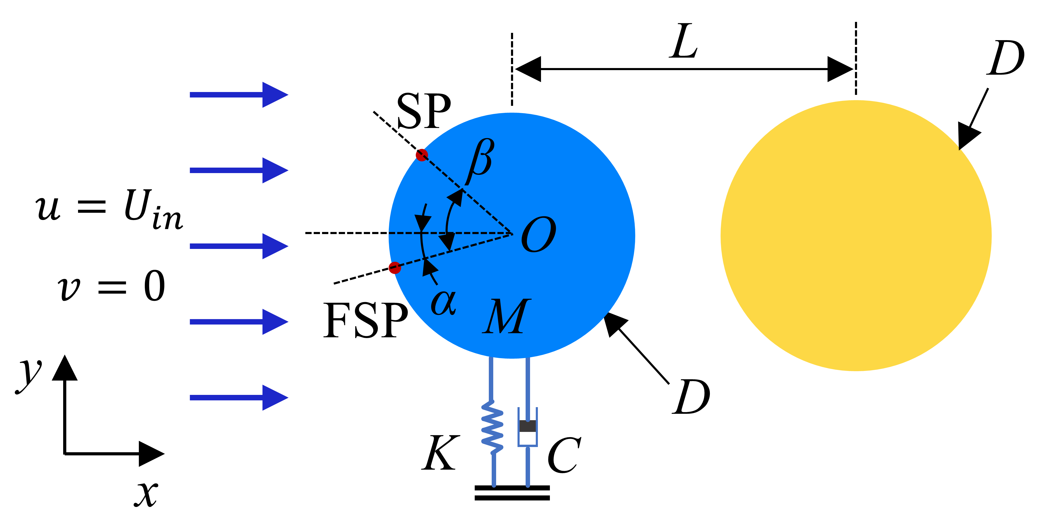
The FIV of an upstream elastically supported cylinder with a downstream fixed control cylinder in the low Reynolds number regime is of present interest; see the problem schematic in Fig. 1. The single-degree-of-freedom elastically supported circular cylinder is located upstream and can move freely along the direction. The fixed control circular cylinder is located downstream. The initial state of the two cylinders is on the same horizontal line. The nondimensional distance between the centers of the two cylinders, , is systematically varied from to , where is the diameter of the circular cylinder.
To facilitate the analysis in the later sections, Fig. 1 shows the front stagnation point of the cylinder marked as FSP and the separation point of the boundary layer marked as SP. The angle is defined as the angle between the front stagnation point and the center horizontal line of the cylinder. The angle is positive when the front stagnation point is above the center horizontal line of the cylinder, and negative when it is below. The angle is the angle between the separation point of the boundary layer and the front stagnation point.
II.2 Governing equations
The viscous Newtonian flow is governed by the continuity and unsteady incompressible Navier-Stokes equations as given in the dimensionless form in Eqs. 1 and 2.
| (1) |
| (2) |
where () denotes the dimensionless time, () are the dimensionless velocity components, () are the dimensionless coordinates, () is the dimensionless pressure, and () is the Reynolds number. Here, is the diameter of the cylinder, is the free-stream velocity, is the dimensional time, are the dimensional coordinates, , , , are the dimensional velocity components, pressure, density, and kinematic viscosity of the fluid, respectively. The finite volume method is used to solve the incompressible flow governing equations. The convection terms are discretized in a second-order upwind scheme, and the pressure and velocity coupling are solved by the SIMPLE algorithm. It is known that for a single cylinder subjected to uniform flow, the vortex shedding occurs when and the wake becomes three-dimensional when (Williamson et al., 1988). Hence, the present study is focused on the low regime; ranging from 50 to 170.
The structural system consists of a fixed DC and an elastically supported UC with a single degree of freedom (sdof) along the cross-flow direction. A typical mass-spring-damper dynamic model describes the motion characteristics of the elastically supported circular cylinder. The motion of the UC in the ‘y’ direction is governed by a second-order linear differential equation describing the dynamics of a sdof system as follows:
| (3) |
where represents the structural mass, represents the system stiffness, and , where is the structural natural frequency. is the displacement of the UC, and denotes the lift force along the ‘y’ direction acting on the cylinder. Equation 3 can be non-dimensionalised using the diameter and the free stream velocity as the length and velocity scales, respectively, as follows:
| (4) |
where nondimensional displacement , damping ratio , reduced velocity , and mass ratio . Here, is the structural damping coefficient, is the structural stiffness), is the structural mass of the cylinder per unit length, and is the structural natural frequency. In this study, is proportional to as the natural frequency of the structure , kinematic viscosity of the fluid , and the cylinder diameter are kept constant throughout the study. The and of the oscillating cylinder system are considered to be 1.113 and 0.01, respectively, following Zhou, So, and Lam (1999). The structural governing equation is numerically solved using the fourth-order Runge-Kutta method.
The two-way coupled fluid-structure interaction (FSI) simulations are carried out using the CFD software Ansys Fluent based on the fully–implicit algorithm, where the structural equations are incorporated through user-defined functions. To calculate the two-way coupled response of the UC, the N-S equations are coupled with the structural governing equations in a staggered manner. The second-order accurate spatial and temporal discretization schemes are used in this study with the absolute and relative tolerance criteria kept at .
II.3 Verification and Validation
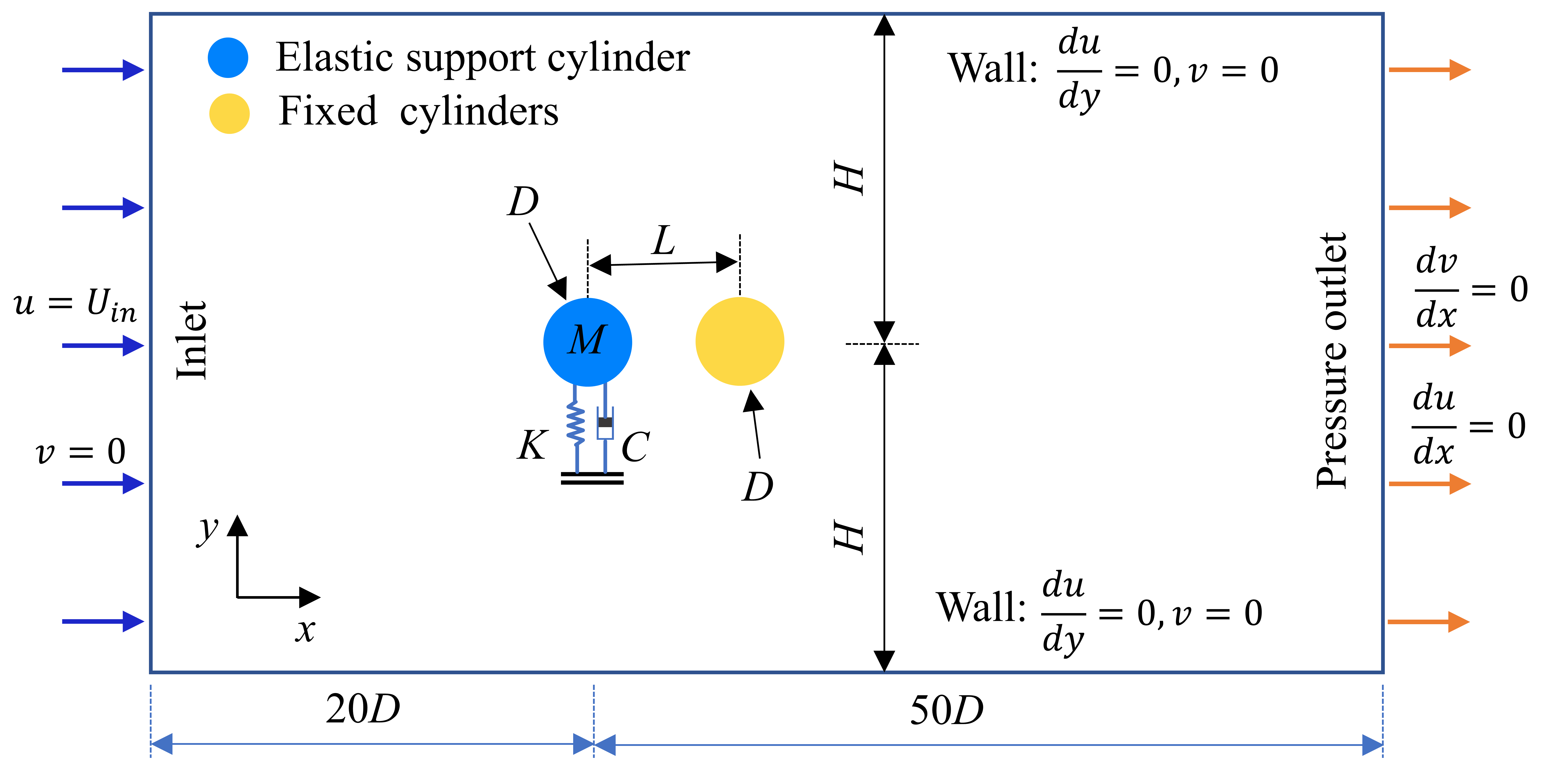
The entire computational domain is rectangular with a size of , where is the diameter of the circular cylinder and is half of the width of the flow field. In the flow direction, the distance between the center point of the elastically supported cylinder and the inlet is , while the distance is from the center of the elastically supported cylinder to the outlet. The boundary conditions are shown in Fig. 2. The boundary settings of the computational domain include the velocity inlet with and , the pressure outlet with and , and the symmetric upper and lower walls with .
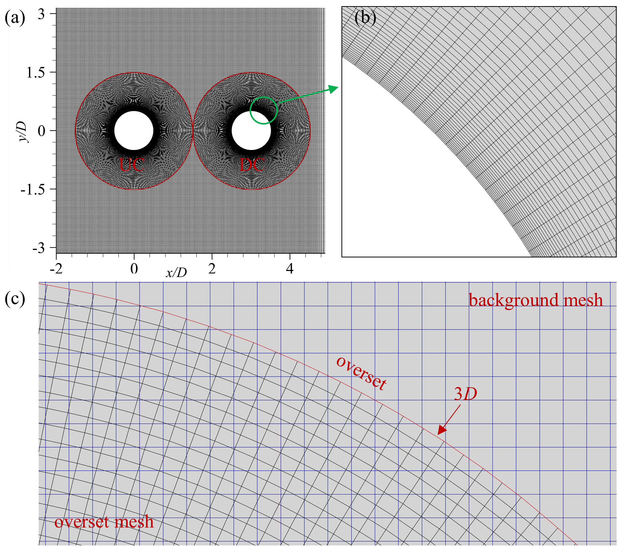
To avoid the numerical instability caused by the excessive mesh deformation due to the large displacement of the upstream elastically supported cylinder, the overset meshing strategy is used in the present study. The computational mesh is shown in Fig. 3, which consists of a background mesh and two overset meshes. The partial mesh of the tandem cylinder is shown in Fig. 3(a), and Fig. 3(b) shows an enlarged view of the cylindrical boundary grid. The boundary of the overset mesh domain is , as seen in Fig. 3(c). To accurately capture the flow-field structures, the perimeter of the cylinder is discretized at equal intervals, and the thickness of the first layer grid around the cylinder structure and the mesh growth ratio in the radial direction are and , respectively. Additionally, the same grid density is used for both overset grid domains.
The effect of domain size on the results is checked by varying the cross-flow height (, , and ) at and . The same foreground mesh for the cylinder walls and the same grid size growth rate are used in these three cases. The time step in the domain-independence study is set to 0.008, meeting the requirement of the maximum Courant number to be less than unity to ensure the stability of the solution scheme. The simulation results are shown in Table 1, the maximum difference is less than . To reduce the computational cost, the value of is considered by comparing the results of , , and for these three cases.
| Background elements | Overset elements | |||||
|---|---|---|---|---|---|---|
| 80896 | 49128 | 0.008 | 0.595 [-] | 1.7309 [-] | 0.1796 [-] | |
| 98784 | 49128 | 0.008 | 0.596 [0.17%] | 1.7353 [0.25%] | 0.1799 [0.17%] | |
| 102144 | 49128 | 0.008 | 0.596 [0.00%] | 1.7418 [0.37%] | 0.1799 [0.00%] |
Next, the mesh size and time-step independence studies are carried out, keeping the computational domain fixed at at and . Case 1, Case 2, and Case 3 are used to check for the grid convergence; and Case 2 and Case 4, with Case 2 being the reference case, are used for non-dimensional time step study. The comparison of vibration response results is presented in Table 2. The number of mesh elements of the three groups is gradually increased. Comparing Case 2 and Case 1, the differences in the maximum dimensionless amplitude , the mean value of the drag coefficient , and the root mean square of the lift coefficient are found to be 0.17%, 0.04%, and 0.45%, respectively. When the number of elements is further increased to achieve Case 3, the differences are reduced to 0%, 0.08%, and 0.11%, respectively. In the time-step independence results, the difference is less than 0.2%. Based on these results, the Case 2 mesh with a non-dimensional time step of 0.003 is selected for further simulations in this paper.
| Case | Background elements | Overset elements | ||||
|---|---|---|---|---|---|---|
| Case 1 | 80896 | 42008 | 0.003 | 0.594 [-] | 1.7492 [-] | 0.1784 [-] |
| Case 2 | 92736 | 49128 | 0.003 | 0.593 [0.17%] | 1.7499 [0.04%] | 0.1792 [0.45%] |
| Case 3 | 106029 | 56248 | 0.003 | 0.593 [0.00%] | 1.7513 [0.08%] | 0.1794 [0.11%] |
| Case 4 | 92736 | 49128 | 0.001 | 0.592 [0.17%] | 1.7516 [0.10%] | 0.1791 [0.06%] |
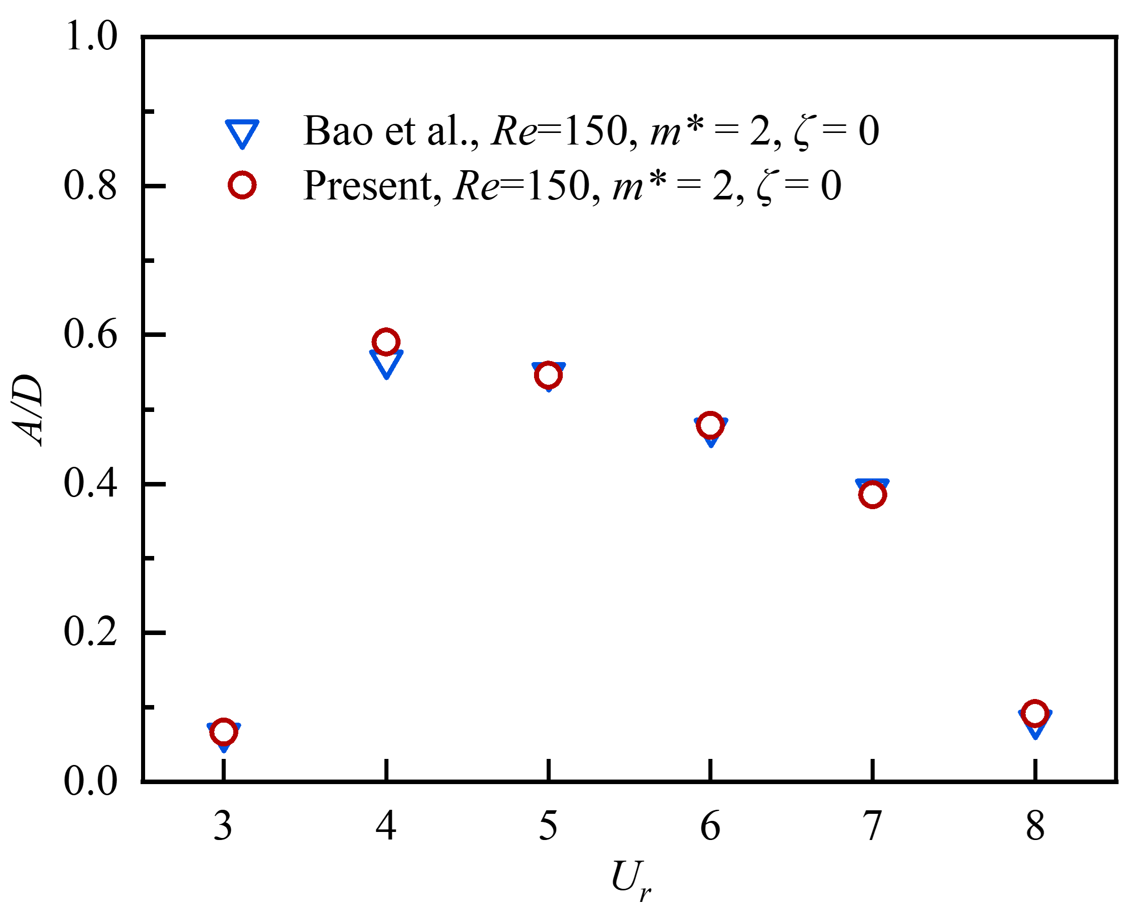
With the chosen simulation setup, the results of the VIV of a single cylinder obtained using the present fluid-structure interaction solver are compared with the reference results of Bao et al. (2012) in the similar regime to check its efficacy. Using the same parameters as Bao et al. (2012), the comparison of dimensionless displacement of the cylinder is shown in Fig. 4. It can be seen that the present results are in good agreement with the reference results. Hence, the present solver can be used for the low regime with confidence.
III Flow field characteristics
In order to understand the effect of a downstream control cylinder, we systematically study the FIV characteristics of the primary cylinder and the underlying wake dynamics for a range of and values. We first characterize the wake patterns through a detailed regime map and unravel the vortex interactions that underline the manifestation of different variety of wake patterns.
III.1 Characterization of different Wake regimes
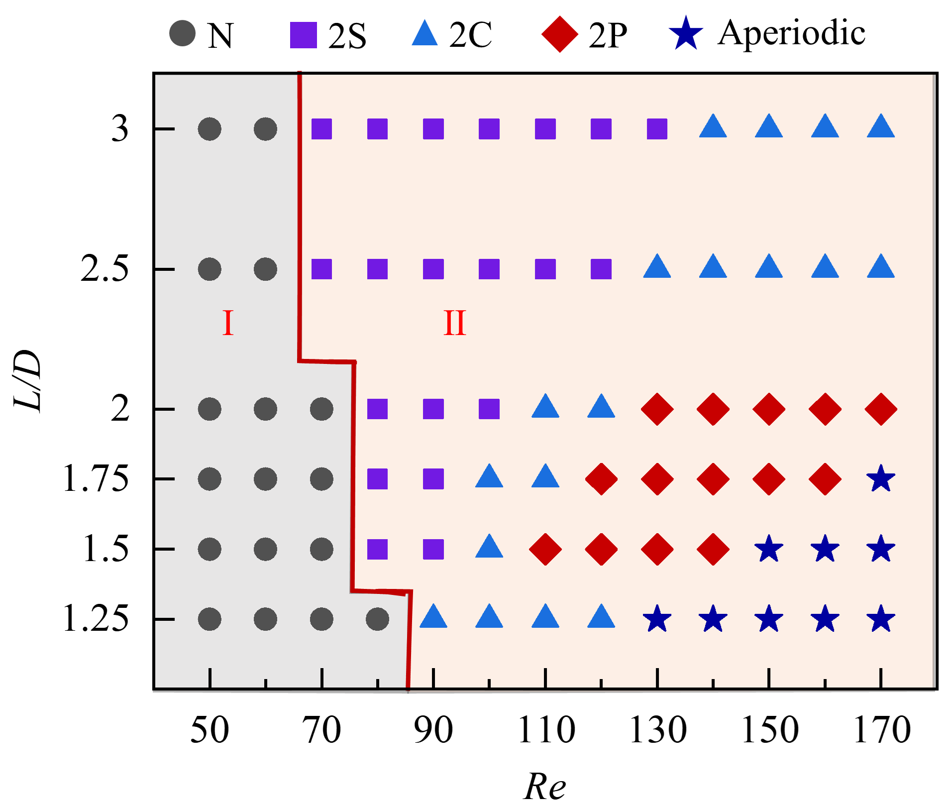
Different wake regimes are characterized by varying and values, and the wake regime map is presented in Fig. 5. The wake can be broadly distinguished into two different regimes according to the development of the shear layer (Ali, Islam, and Janajreh, 2022): the steady flow regime (denoted by I, where there is no vortex shedding behind the DC); the alternating attachment regime (denoted by II). As the value increases from 1.25 to 3, the range of , where steady flow occurs gradually decreases from to , and no vortex shedding occurs in this region. On the other hand, the alternating attachment regime is predominant for . The wake patterns are further classified according to the vortex shedding pattern of the two cylinders. As shown in Fig. 5, the alternating attachment regime can be divided into four sub-regions, namely (i) ‘2S’ (two single isolated vortices are shed in an oscillation cycle of the cylinder), (ii) ‘2C’ (two counter-rotating vortex pairs are shed in an oscillation cycle of the cylinder), (iii) ‘2P’ (two co-rotating vortex pairs are shed in an oscillation cycle of the cylinder)(Stremler et al., 2011), and (iv) aperiodic wake regime (vortex shedding takes place completely irregularly with no periodicity), respectively. It can be seen from the flow regime classification diagram that the characteristics of the flow field are sensitive to and . A detailed analysis of the flow field interactions is presented in the next subsection.
III.2 Underlying vortex interactions
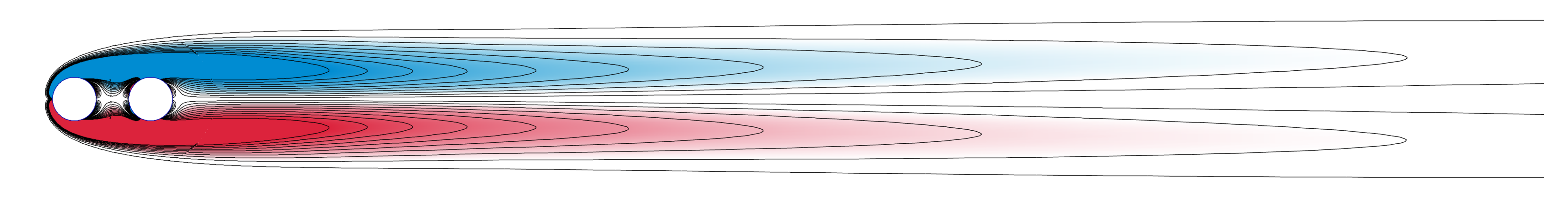
The wake patterns for the steady flow regime and the ‘2S’ vortex shedding pattern in the alternate reattachment regime are shown in Fig. 6 and Fig. 7, respectively. The vorticity is non-dimensionalized, considering as the reference velocity scale and as the reference length scale, as . In the steady flow regime (at = 1.75 and = 60), the shear layer, separating from the UC, directly crosses over the DC, and no vortex shedding takes place behind the DC; see Fig. 6. The displacement () and lift coefficient () of the UC are practically zero in this regime. Fig. 7 shows the temporal evolution of the flow structures around the cylinders, the pressure coefficient () around the cylinders, and the corresponding time-histories of the and (at = 1.75 and = 80). Here, the clockwise vortices are marked in blue (negative), while the counter-clockwise vortices are marked in red (positive). The resulting wake pattern is characterized as a typical Kármán vortex street.
At 1# instance, the vortex P1 is seen to be separated from the shear layer of the DC, while the positive shear layer P2 generated by UC remains completely attached to the lower surface of DC. The negative vortex above the DC N1 is shed alternatively, and the negative shear layer N2 in the gap begins to roll up, adhering to the DC. As a result, the pressure on the upper surface of UC is lower than that on the lower surface, and the pressure difference of the DC is opposite to that of UC at this moment. At 2# instance, as the UC reaches the maximum positive displacement, the negative shear layer in the gap starts adhering to the upper surface of DC. The shear layer P2 rolls up and squeezes the vortex N1. The pressure on the upper surface of UC increases significantly. At 3# instance, the vortex N1 is separated, and the remaining shear layer merges with the negative shear layer N2, forming a new shear layer labelled N2∗. The negative pressure areas of UC and DC are seen to get reversed compared to the 1# instance. The vortex shedding process at 3# to 5# instances is the same as that at 1# to 3# instances, but the vortex shedding direction is the opposite. In Fig. 7(a), the and the time histories follow the same trend. Within the ‘2S’ pattern sub-region, there is a distinctive wake pattern characterized by two-layered vortex streets, as shown in Fig. 7(b). This phenomenon is more pronounced at lower and .
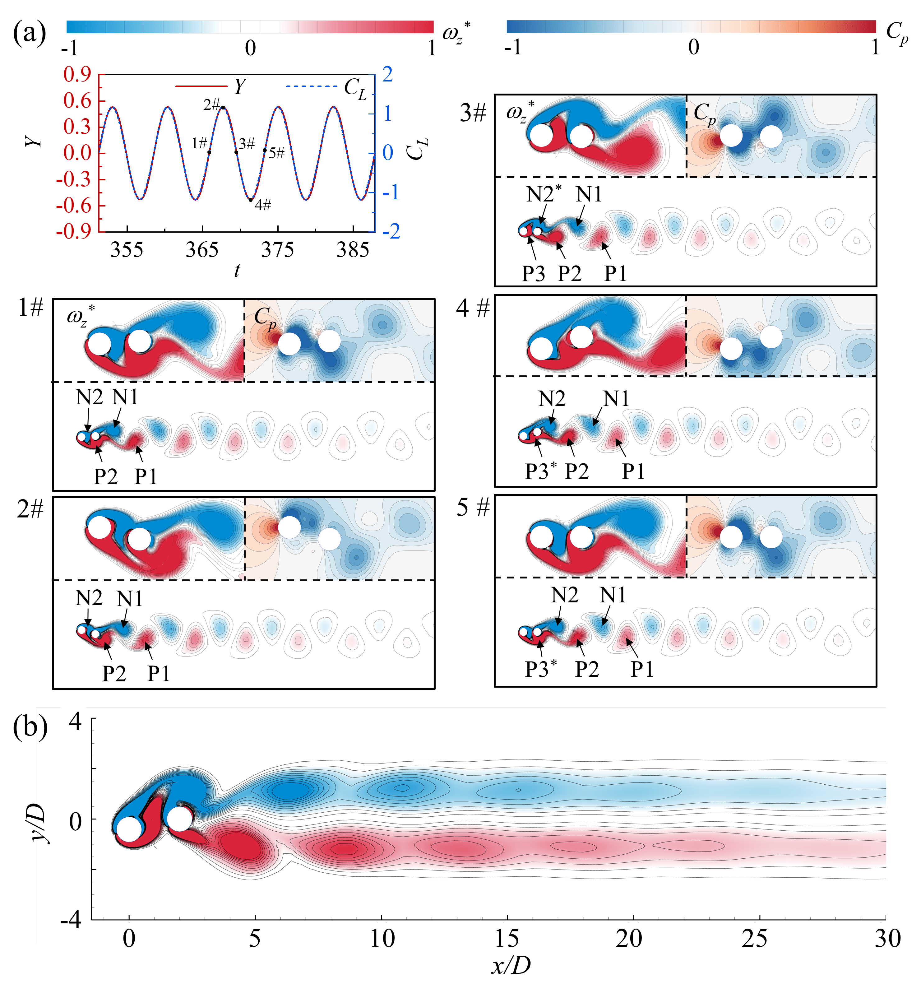
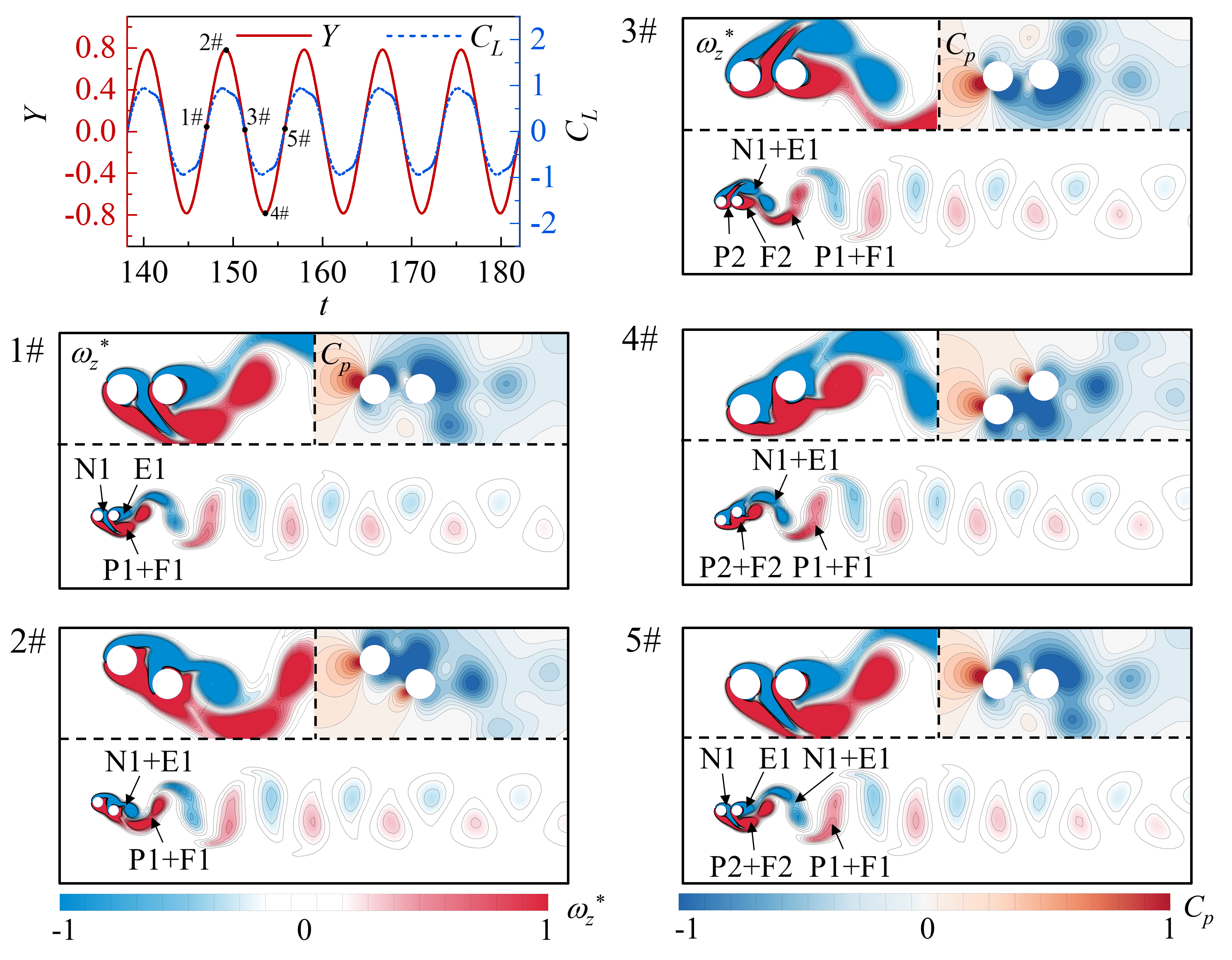
As shown in Fig. 5, the ‘2P’ and ‘2C’ vortex-shedding patterns occurs in a wide range of and . Figs. 8 and 9 show the evolution process of ‘2P’ and ‘2C’ vortex-shedding patterns, the around the cylinders for different and values, respectively. In Fig. 8, the cylinders are situated at the middle position at 1# instance. The remaining shear layer from the negative shedding vortex of the previous cycle is marked as N1, while the negative shear layer within the gap is labeled as N2. Below the tandem cylinder, the positive shear layer from the UC has merged completely with that of the DC and is marked as P2. Both UC and DC have small pressure on the upper surface and high pressure on the lower surface. At 2# instance, the UC reaches the positive maximum displacement. The downward-curling vortex N1 squeezes the shear layer P2, separating it from DC. On the upper surface of the DC, the shear layer N2 is fully attached to the DC, while the shear layers N1 and N2 remain separate. Conversely, the shear layer N2 promotes the shear layer N1 to separate from DC. At 3# instance, the UC returns to the middle position. The shear layer P2 detaches from the DC due to the downward-curling shear layer N1. Due to the pushing and truncation effect of the shear layer N2 and P3, the shear layer N1 also sheds from DC. During the half cycle (from 3# to 5# instances) with negative motion displacement, the vortices N2 and P3 shed from the DC in a similar manner. In the downstream far-field of the DC, the vortices with the same direction between the two periods merge. The interference effect of DC results in a noticeable harmonic component of the frequency spectra of , with the two peaks being almost equal.
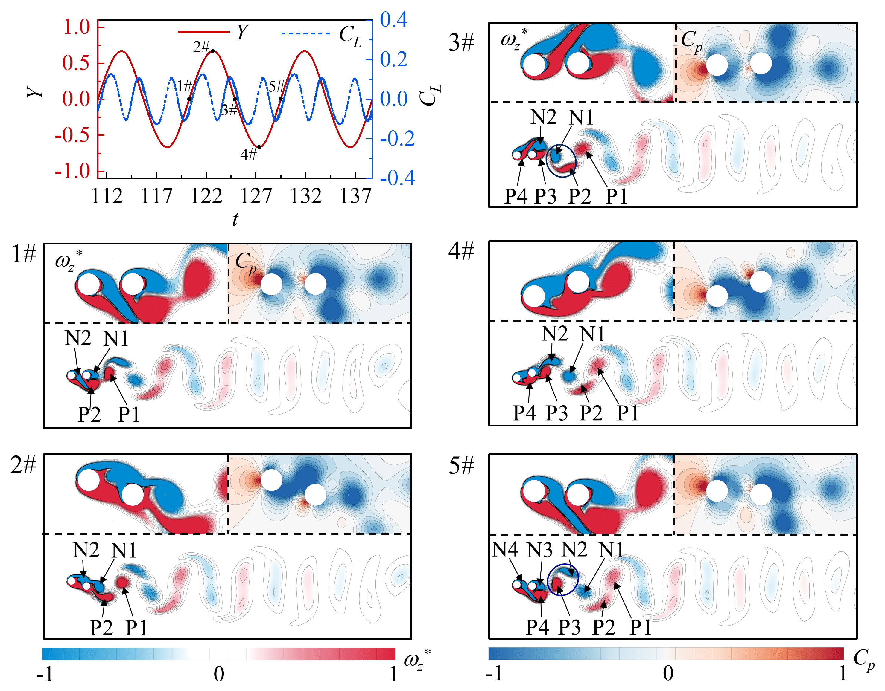
Figure 9 illustrates the evolution process of the ‘2C’ vortex shedding pattern. This vortex shedding pattern is observed between the ‘2S’ and the ‘2P’ or ‘aperiodic’ wake regimes (when ) and on the right side of the ‘2S’ pattern (when ). At 1# instance, the positive shear layers P1+F1 below DC are connected, and there are two shear layers, named E1 and N1, above DC and in the gap. At 2# instance, the shear layer N1 attaches to the upper surface of DC and combines with E1 to form the new vortex named N1+E1. At time 3#, vortex P1+F1 shedding from the DC. Compared with shear layer P3 at 3# instance in Fig. 8, the truncation effect of the remaining shear layer F2 is weakened, and the combination of N1+E1 is not destroyed, but shedding together from the DC at 5# instance in the negative half cycle. In the downstream far field of the DC, two vortices with the same direction merge completely into a vortex, the same as the typical Kármán vortex street. The evolution process of the ‘2S’, ‘2C’ and ‘2P’ patterns reveals that with increasing , the vortex shedding pattern gradually transitions from the ‘2S’ pattern to the ‘2P’ pattern, while the downstream far-field will evolve to the typical Kármán vortex street.
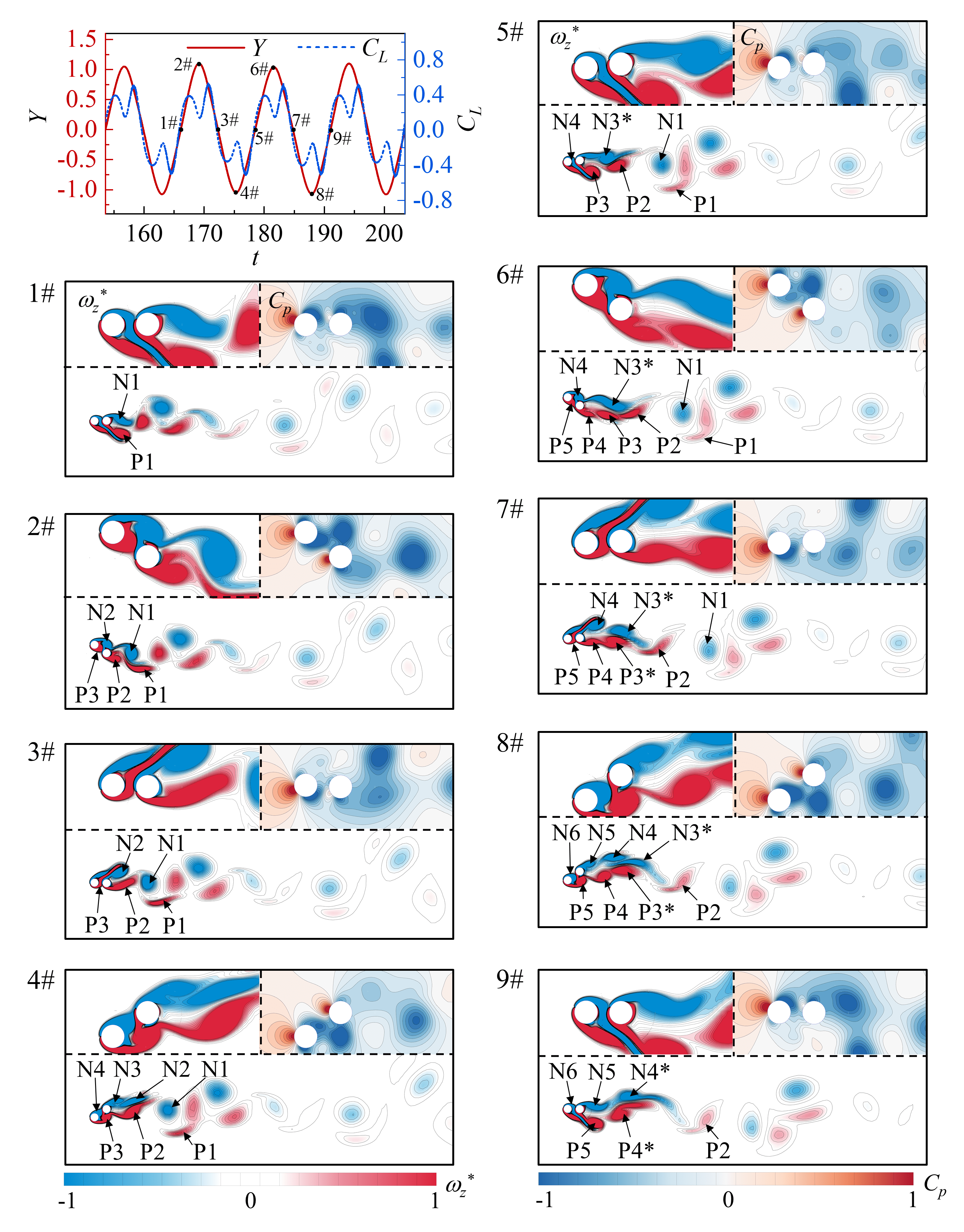
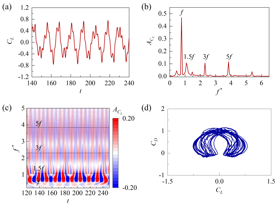
At small and high , the wake behind the tandem cylinders is characterized by an aperiodic vortex shedding pattern (‘aperiodic’ pattern), represented by a five-pointed star in the sub-region of Fig. 5. The corresponding time-histories of and of the UC, the around the cylinders, and the evolution process of vortex shedding are shown in Fig. 10. It can be noted that the shedding pattern around the UC and the displacement of the UC are mostly periodic. However, the interference of the gap flow, and in turn, the wake downstream becomes aperiodic. At 1# instance, vortices N1 and P1 are formed behind the DC. At 2# instance, as the UC reaches its maximum positive displacement, the negative shear layer N2 is attached to the upper surface of DC. The positive shear layer below UC is truncated by DC, forming parts P2 and P3. Simultaneously, vortices N1 and P1 shed from the DC. At 3# instance, shear layer P3 cuts vortex N2 into two parts, forming the shear layers N3 and N4 at the 4# instance. It can be seen that at 4# instance, the shear layer P3 has attached to the lower surface of DC, and the vortex P2 begins to separate from DC. At 5# instance, the vortex P3 is divided into two parts by the shear layer N4. A new vortex labelled N3∗ emerges due to the merge of N2 and N3. At 6# instance, the shear layer N4 attaches to the upper surface of DC, and N3∗ separates from the DC. Below the DC, the vortices P2, P3, and P4 form a long, narrow vortex strip. The vortex P3 merges with part of P4 to form a new vortex, P3∗, at the 7# instance. The vortex N4 is divided into two parts by the shear layer P5 at 7# instance and evolves into vortices N4, N5 and N6 at 8# instance. Finally, the vortex N4 and N3∗ also merge to form N4∗ at 9# instance, and the same is for vortex P4 and P3∗. The time-history, frequency spectra, wavelet spectra of for the DC, and the phase portraits of and of the DC at and are presented in Figs. 11(a)-11(d), respectively. It can be seen that the time history of is irregular with broadband frequency spectra, indicative of the aperiodic nature of the flow field. It is evident that there is no distinct periodic attractor in the phase space. In comparison to the other three sub-regions in Fig. 5, this sub-region exhibits a complex process of wake vortices shedding and merging, lacking regularity in the vortex shedding. The instability of the shear layer separated from the UC can be attributed as the primary agency for triggering this aperiodicity over the DC. Hence, we classify this flow regime as an ‘aperiodic’ wake pattern.
III.3 Analysis of wake characteristics
The wake characteristics behind the tandem cylinder system are analyzed in this subsection. When the UC is in the equilibrium position just before the start of the upward movement, the flow field contour is considered to calculate the vortex width at a position of = 10 downstream. For the streamwise distance, the center-to-center distance between the two adjacent co-rotating vortex cores is calculated at = 10 downstream. All the cases are represented with the same contour levels. It is worth noting that, for the aperiodic cases, the average and standard deviation of the wake width and streamwise distance of the 10 consecutive oscillation cycles are calculated; the results are plotted with the corresponding error bars.
Figure 12(a) illustrates the variation of the near-wake vortex width () for different and values. The error bars in = 1.25, 1.5, and 1.75 represent the statistical results of the varying in the ‘aperiodic’ pattern region. Two representative cases are presented in Fig. 12(b). At , except for the ‘aperiodic’ regime, the wake width gradually increases with the increase of reduced velocity, however, with a decreasing rate of increment. In the ‘aperiodic’ regime, a variety of shedding patterns appear due to complex vortex shedding and merging; there is a different wake width in the wake flow. Comparing the vortex shedding pattern classification in Fig.5, the value increases rapidly in the ‘2S’ and ‘2C’ regimes, while only small changes are observed in the ‘2P’ region. For values between 2.5 to 3 and , the vortex shedding exhibits a ‘2S’ pattern with a double-layered vortex street, and the varies of is small. Subsequently, as the vortex shedding transformed into ‘2S’ pattern with the single-layer vortex street, the gradually increases.
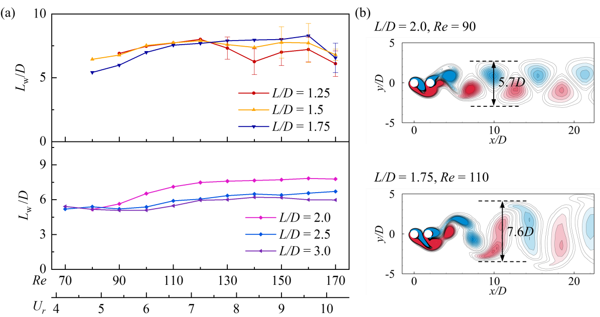
Figure 13(a) presents streamwise distance () for the two adjacent co-rotating near-wake vortices as a function of and . Two representative cases are presented in Fig. 13(b). Different values are observed in the consecutive vortex shedding periods in the ‘aperiodic’ wake regime, which can be attributed to the complex vortex shedding behind the DC. When ranges from 2.5 to 3, increases with increasing , indicating a decrease in the vortex shedding frequency. Based on the vortex shedding pattern classification in Fig. 5, the gradually increases as the vortex shedding pattern evolves from ‘2S’ to ‘2C’ and ‘2P’. When located in the two-layered vortex street, the change of is small.
IV Flow-induced vibration characteristics
In the previous section, the different wake regimes observed with different are analyzed. The results have shown that a strong interference effect due to the presence of the DC affects the vortex shedding patterns of the UC, in turn significantly altering the associated aerodynamic forces. Next, in this section, the flow-induced vibration characteristics of the UC are presented.
IV.1 Amplitude and frequency characteristics
Figure 14 shows the variation of the dimensionless amplitude () and the frequency ratio () of the flow-induced vibration response of the UC as a function of , in comparison to the results of a single cylinder and large spacing ratio . Here, the amplitude is defined as , where and are the maximum and minimum response amplitude, respectively. Figure 15 presents the dynamical classification of the vibration response, in which I represent the steady flow regime, where the displacement of the UC is close to 0; II is the alternating attachment regime. Two vibration types of the UC are distinguished by colour blocks, extended VIV and interference galloping (IG). As can be seen in Fig. 14(a), the dimensionless amplitude of the UC increases gradually with increasing and has a similar trend when varies between 1.25 and 1.75. In addition, the amplitude is the largest when the . When and , the dimensionless amplitude shows a decreasing trend with increasing ; the amplitude does not change significantly for . It can be seen from Fig. 14(b) that the dimensionless frequency of the UC gradually increases with increasing after the UC starts vibrating. Besides, the dimensionless frequency also increases with increasing .
When is 1.25, 1.5, and 1.75, the dimensionless frequencies are locked-in at 0.62, 0.77, and 0.87, respectively, and the vibration response of the UC can be characterized as the interference galloping (Dielen and Ruscheweyh, 1995). The interference effect of the DC on the vibration of the UC gradually weakens with the increasing . When is greater than a critical threshold, the response of the UC transitions to pure VIV (Chunning et al., 2014). As can be seen from Figs. 14(a) and 14(b), when , the dimensionless amplitude and the frequency ratio of the UC response are completely consistent with that of a single circular cylinder. In Fig. 14(a), when is between 2.5 and 3, the dimensionless amplitude reaches its maximum at = 4.8, and then gradually decreases with the increasing . It is worth noting that, when , the dimensionless displacement of the UC is larger than that of a single cylinder. The dimensionless frequency of the UC increases from 0.68 to 1.37 when is between 2.5 and 3. When = 2, the maximum frequency ratio is 1.02 at = 10.2, which is smaller than that observed for the between 2.5 to 3. This indicates that due to the interference effect of the DC, there is a wider lock-in region when = 2. According to Chen et al. (2022), when falls between 2 and 3, it can be classified as extended VIV. The range of also aligns with Bokaian and Geoola (1984).
According to the classification results of the wake regime presented in Fig. 15, there is no vortex shedding behind the cylinder in the steady flow regime, and the displacement of the UC is close to zero in this regime. As increases, the wake changes from the steady flow to the alternate attachment regime, and the UC begins to vibrate with a large amplitude. Comparing with the classification in Fig. 5, the wake shifts from steady flow to the ‘2S’, and then evolves into ‘2C’, ‘2P’, and ‘aperiodic’ pattern with increasing at = 1.5, is different from the evolution process from ‘2C’ to ‘aperiodic’ pattern at = 1.25, resulting a small starting velocity and larger vibration amplitude of the former. At = 1.75, the larger transition range of the ‘2P’ pattern and smaller distribution of the ‘aperiodic’ pattern results in smaller vibration amplitudes compared with = 1.5.
IV.2 Phase difference characteristics
Using the Hilbert transform, the instantaneous phase of the lift coefficient and the dimensionless amplitude is calculated, and then the instantaneous phase difference between the two is obtained. Finally, the root mean square value of the instantaneous phase difference () is estimated to evaluate the phase characteristics of the lift coefficient and the dimensionless amplitude; see Fig. 16. When , the gradually increases with the increasing . The increases to when and , and increases to when increases to 2. Consequently, the increase in the dimensionless displacement decreases with increasing . At = 2, the increases significantly, and the enhancing effect of lift on the cylinder vibration weakens, resulting in a small change in the amplitude of the UC. The of the UC are similar to that of the single circular cylinder for . When and , the reaches (the lift coefficient and the dimensionless displacement are in anti-phase condition), resulting in continuous decreases of the response amplitude of the UC with increasing .
V Force characteristics of the upstream cylinder
Figure 17 shows the variation of the root mean square value of the lift coefficient () and the mean value of the drag coefficient () of the UC with increasing and . It can be seen from Fig. 17(a) that the is almost zero at the steady flow regime due to the absence of vortex shedding. As the increases, the undergoes a sudden jump with the change in flow regime. When and between 80 to 90 or and between 90 to 100, the change of the is very small in the alternate attachment regime, and then gradually decreases with the increasing . On the contrary, the of the UC jumps to the maximum along with the change of flow regime and then decreases with increasing at the condition of . It is worth noting that the slightly increases when and compared to the single cylinder case. This coincides with a slow decreasing trend of the response displacement of the UC. It can be seen from Fig. 17(b) that the value for different follows the same trend. There is a small decrease in the steady flow regime. Then, it increases significantly after the onset of the UC vibration and subsequently decreases with increasing . The of the UC is larger than that of a single cylinder when . It is worth noting that the critical for steady to unsteady flow transition decreases as increases. At , the interference effect of the DC on the UC disappears, and the UC and the single circular cylinder are seen to have the same and .
The time-histories and frequency spectra of for and different are shown in Fig. 18. It can be seen that the frequency spectra primarily comprise a dominant frequency peak (vortex shedding frequency) and its triple harmonic. Due to the interference effect of the DC on the vortex shedding, the triple frequency harmonic component on the time history of becomes more significant as increases. Notably, at = 160, the magnitude of the triple harmonic component exceeds the magnitude of the fundamental frequency and becomes the dominant shedding frequency. The earlier studies (Wu, Ge, and Hong, 2012) showed that the triple harmonic lift is related to three vortices shedding behind the cylinder, resulting in a ‘2T’ vortex shedding pattern. For the present tandem cylinder system, although the ‘2T’ vortex shedding pattern does not appear, the triple harmonic frequency of of UC can be attributed to the shear layer interaction in the intermediate gap flow. The wavelet analysis of the time-history is carried out for = 120 and = 160 at = 2; see Fig. 19. The contour represents the variation of the Continuous Wavelet Transform coefficient with non-dimensional time. The black dotted line is the natural frequency () of the elastically supported cylindrical structure. From the contour in Fig. 19(a), it can be seen that when the = 120, the peaks A1 and C1 at the positive half period of the lift coefficient are located between the positive and negative peaks of the triple harmonic component. When = 120, the two peaks are mainly affected by the first-order fundamental component. While = 160, the variation of the lift coefficient is similar to that of = 120; see Fig. 19(b). However, the peaks (A2 and C2) of the lift coefficient coincide with the peak of the triple harmonic component, that is, the lift coefficient is mainly dominated by the triple frequency harmonic lift.
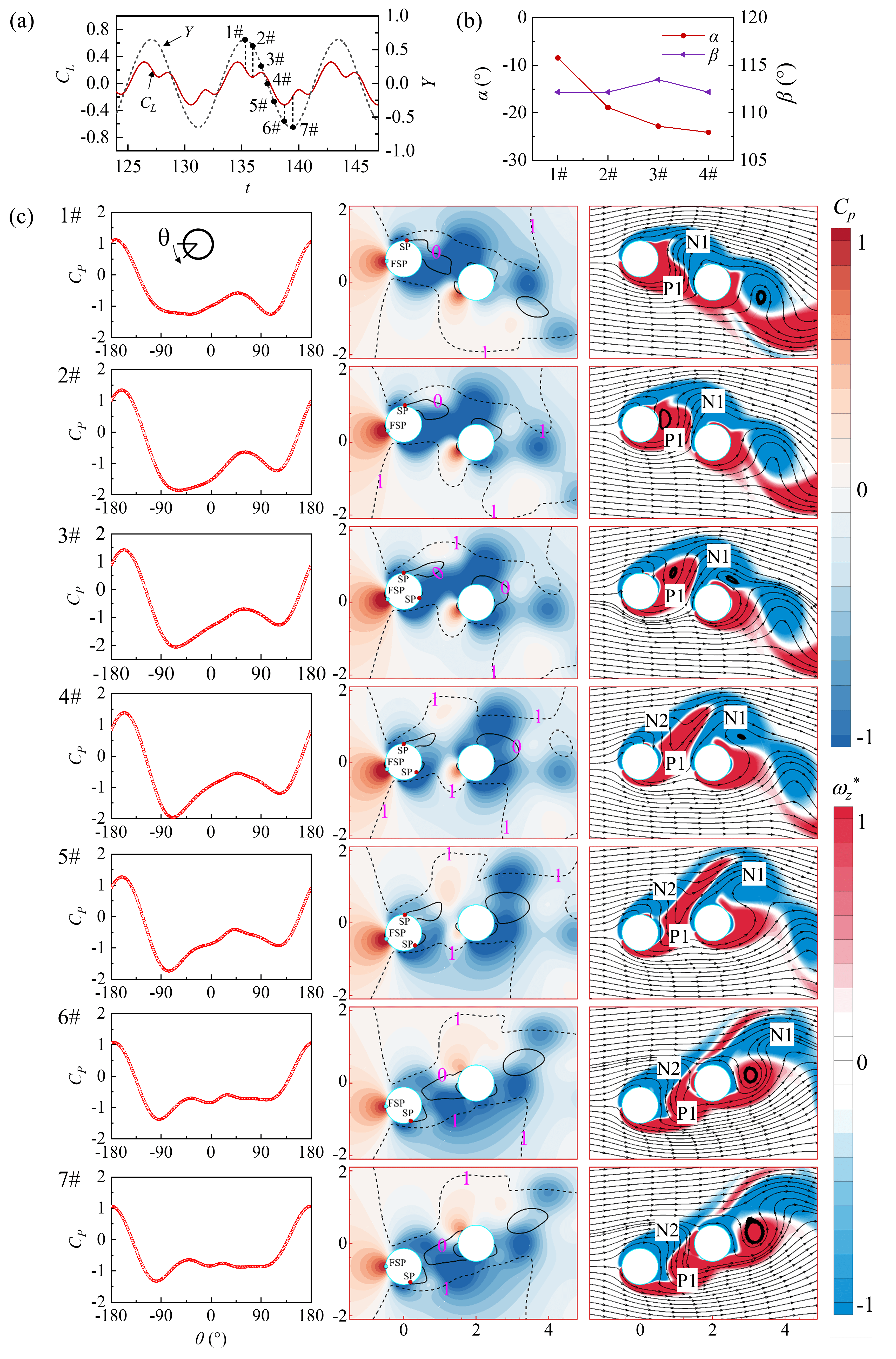
Figures 20-22 show the angle of the separation point of the boundary layer, the variation of the surface pressure coefficient (), the contour of and vorticity at different instances of and time histories for different . Fig. 20(a) shows the lift coefficient and dimensionless amplitude of the UC. In the contour, the solid and dotted lines represent the velocity and , respectively, where is the normalized velocity. The separation point of the boundary layer can be determined from , while the distance between and indicates the thickness of the shear layer. Due to the symmetric motion of the UC, the angles of and are only shown from 1# to 2# instances in Fig. 20(b). In Fig. 20(c), at 1# instance, the separation point of the boundary layer is located on the upper surface of UC, and the angle between the separation point of the boundary layer and the front stagnation point is 118.7∘ (the definition of the angle is supplemented in Fig. 1). In the vorticity contours, the formation of the clockwise vortex N1 results in the maximum pressure difference between the upper and lower surfaces of the UC, in turn, the maximum upward lift coefficient at the 1# instance. From the instances of 1# to 2#, the shear layer P1 moves with upward velocity and the intensity gradually increases, a small counterclockwise vortex is formed in the gap. Meanwhile, the clockwise vortex N1 begins to shed, and the supply of the boundary shear layer to the vortex N1 is weakened. The pressure on the upper surface of UC increases while the pressure on the lower surface decreases, causing the lift coefficient to gradually decrease to zero. From 2# to 3# instances, the counterclockwise vortex P1 causes a downward velocity in the gap, the pressure on the lower surface of the UC is lower than that on the upper surface, and the downward lift coefficient gradually increases. There is no harmonic interference effect at this .
The harmonic components of emerge as the value increases; see Fig. 21(a). It can be seen that the angle between the separation point of the upper surface boundary layer and the front stagnation point is smaller compared to that observed in = 80; see Fig. 21(b). In Fig. 21(c), at 1# instance, the clockwise vortex N1 induces an upward flow velocity in the gap and generates a positive lift force on the UC. At 2# instance, the upper separation point of the boundary layer moves counterclockwise. The shear layer P1 is displaced to the rear side of the UC, and a small counterclockwise vertex is formed. The overall pressure level on the lower surface reduces, resulting in a decreased lift coefficient. From 2# to 3# instances, the counterclockwise vortex in the gap moves upward with the water flow, disrupting the connection between vortex N1 and the upper boundary layer of the UC. The separation point of the shear layer P1 moves downward, and the pressure level on the lower surface of UC increases, resulting in a slightly increased lift coefficient. At the 4# instance, the connection between vortex N1 and UC weakens further, reducing the positive lift coefficient generated by N1 to 0. From the 4# to 7# instances, the growth of shear layer P1 generates a downward lift coefficient. At 6# instance, the shear layer P1 causes a complete downward velocity in the gap. The connection between vortex N1 and UC is completely severed, the pressure on the upper surface of the UC increases to the maximum, and the downward lift coefficient generated by P1 reaches the maximum. At the 7# instance, the enhancement of shear layer N2 leads to a decrease in the pressure on the upper surface and lift coefficient.
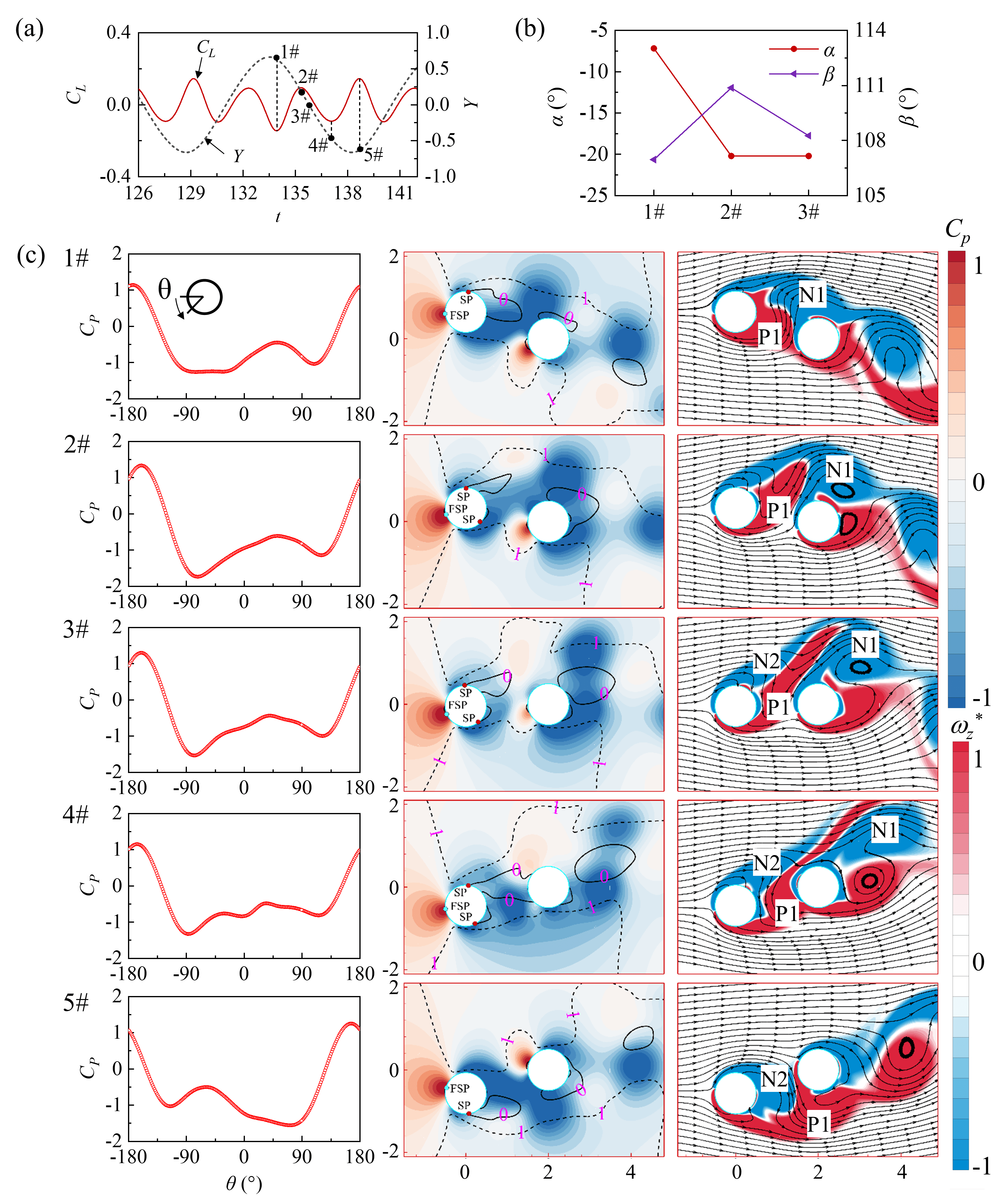
At = 160, the amplitude of the third harmonic frequency of the lift coefficient exceeds the amplitude of the fundamental vortex shedding frequency. As shown in Fig. 22(b), the angle between the front stagnation point and the boundary layer separation point is further reduced compared to that overserved in = 120. At the 1# instance in Fig. 22(c), the UC leave the positive maximum displacement position. The vortex N1 causes an upward flow velocity in the gap, and the positive shear layer P1 moves to the rear of the UC with the water flow. The time-history curves in Fig. 22(a) show that is minimum at this instance. From 1# to 2# instances, the shear layer P1 begins to cut off the connection between vortex N1 and the UC but is not destroyed. The separation point of the boundary layer on the lower surface moves downward, resulting in a decrease in the overall pressure on the lower surface of the UC. From 2# to 4# instances, the flow velocity in the gap turns downward, and the separation point of the lower boundary layer gradually moves downward. The pressure on the lower surface is still lower than that on the upper surface, and the lift coefficient gradually decreases with the variation of vortex P1. At the 4# instances, the connection between vortex N1 and the UC is completely severed, causing an increase in the as the remaining shear layer N2 changes direction in the gap. Figures 21 and 22 show that after the vortex is cut off by the shear layer in the gap, the growth of the remaining shear layer in the gap primarily controls the change in the lift coefficient. This remaining shear layer acts like a switch, and the variation in the lift coefficient depends on its position in the displacement curve. This behaviour differs from the third harmonic lift caused by the ‘2T’ pattern.
VI Conclusions
In the present work, two-dimensional numerical simulations are carried out to study the influence of a fixed DC on the FIV of an elastically supported UC. The simulations are performed for a range of from 50 to 170, and a range of from 1.25 to 3. The influence of and on the FIV of UC is investigated in detail. The main conclusions are summarized as follows:
-
•
There is a significant impact of and on the wake flow regime.Two distinct flow regimes, namely the steady flow, and alternating attachment, have been observed. The steady flow regime occurs in the low regime. The range for the steady flow regime decreases with increasing . With the increase in or , the flow-field transitions from the steady flow regimes to an alternating attachment regime, which comprises the largest area in the map.
-
•
Various vortex shedding patterns are observed behind the tandem cylinders due to the hindrance of the DC on the vortex shedding of the UC. At = 1.25, two vortex shedding patterns, ‘2C’ and ‘aperiodic’, are observed. For is between 1.5 and 1.75, four different vortex shedding patterns are observed: ‘2S’, ‘2C’, ‘2P’, and ‘aperiodic’. At = 2, three different vortex shedding patterns, ‘2S’, ‘2C’ and ‘2P’, are observed. When is greater than 2, only the ‘2S’ and ‘2C’ patterns are observed.
-
•
After the UC starts vibrating, the interference effect of the DC at a small slows down the increase rate of between and . As a result, the lift of the UC continuously promotes the increment of the amplitude at a small . When is between 1.25 and 1.75, as the velocity increases, the remains less than , and the corresponding vibration characteristic of the UC is characterized as interference galloping. The lock-in frequency of the UC increases with increasing but is smaller than the natural frequency of the UC. When , the vibration characteristics of UC show extended VIV. In this vibration regime, the lock-in interval of the cylinder is significantly larger than that of a single cylinder, and the amplitude of the lock-in region gradually decreases with increasing the .
-
•
The hindering effect of the DC on the vortex shedding of the UC results in variations in the shear layer in the gap, acting like a switch and altering the distribution of on the UC surface. When the is between 1.25 and 2, the third harmonic frequency of the of the UC increases with increasing . Moreover, at = 2, the amplitude of the third harmonic frequency component will exceed that of the fundamental frequency component of .
The findings of this study will allow us to better understand vibration reduction in tandem cylindrical structures and lead to the efficient design of flow-induced energy harvesters.
VII Acknowledgements
This work was supported by the National Natural Science Foundation of China (Grant No. 52277227), the Science and Technology Research & Development Joint Foundation of Henan Province-Young Scientists (Grant No. 225200810099), and the Program for Science & Technology Innovation Talents in Universities of Henan Province (Grant No. 23HASTIT010).
Data availability statement
The data that support the findings of this study are available from the first author/corresponding author upon reasonable request.
Declaration of interests
The authors report no conflict of interest.
References
- Chen, Dong, and Wang (2021) L. Chen, Y. Dong, and Y. Wang, “Flow-induced vibration of a near-wall circular cylinder with a small gap ratio at low reynolds numbers,” Journal of Fluids and Structures 103, 103247 (2021).
- Hu et al. (2019) G. Hu, J. Wang, Z. Su, G. Li, H. Peng, and K. Kwok, “Performance evaluation of twin piezoelectric wind energy harvesters under mutual interference,” Applied Physics Letters 115, 073901 (2019).
- Zafar and Alam (2018) F. Zafar and M. M. Alam, “A low Reynolds number flow and heat transfer topology of a cylinder in a wake,” Physics of Fluids 30, 083603 (2018).
- Zhang and Ji (2022) Z. Zhang and C. Ji, “Spacing effect on the vortex-induced vibrations of near-wall flexible cylinders in the tandem arrangement,” Physics of Fluids 34, 097123 (2022).
- Zhang et al. (2022) M. Zhang, Y. Song, A. Abdelkefi, H. Yu, and J. Wang, “Vortex-induced vibration of a circular cylinder with nonlinear stiffness: prediction using forced vibration data,” Nonlinear Dynamics 108, 1867–1884 (2022).
- Williamson and Govardhan (2004) C. H. Williamson and R. Govardhan, “Vortex-induced vibrations,” Annu. Rev. Fluid Mech. 36, 413–455 (2004).
- Wang et al. (2020) J. Wang, S. Gu, C. Zhang, G. Hu, G. Chen, K. Yang, H. Li, Y. Lai, G. Litak, and D. Yurchenko, “Hybrid wind energy scavenging by coupling vortex-induced vibrations and galloping,” Energy Conversion and Management 213, 112835 (2020).
- Wang et al. (2021) J. Wang, C. Zhang, M. Zhang, A. Abdelkefi, H. Yu, X. Ge, and H. Liu, “Enhancing energy harvesting from flow-induced vibrations of a circular cylinder using a downstream rectangular plate: An experimental study,” International Journal of Mechanical Sciences 211, 106781 (2021).
- Assi et al. (2006) G. d. S. Assi, J. R. Meneghini, J. A. P. Aranha, P. W. Bearman, and E. Casaprima, “Experimental investigation of flow-induced vibration interference between two circular cylinders,” Journal of Fluids and Structures 22, 819–827 (2006).
- Khan et al. (2022) H. H. Khan, M. D. Islam, Y. Y. Fatt, I. Janajreh, and M. M. Alam, “Flow-induced vibration on two tandem cylinders of different diameters and spacing ratios,” Ocean Engineering 258, 111747 (2022).
- Assi et al. (2010) G. R. d. S. Assi, P. W. Bearman, N. Kitney, and M. Tognarelli, “Suppression of wake-induced vibration of tandem cylinders with free-to-rotate control plates,” Journal of Fluids and Structures 26, 1045–1057 (2010).
- Assi, Bearman, and Meneghini (2010) G. R. Assi, P. Bearman, and J. Meneghini, “On the wake-induced vibration of tandem circular cylinders: the vortex interaction excitation mechanism,” Journal of Fluid Mechanics 661, 365–401 (2010).
- Bakhtiari et al. (2020) A. Bakhtiari, M. Zeinoddini, H. Ashrafipour, and V. Tamimi, “The effect of end conditions on the flow-induced vibration of circular cylinders in tandem arrangements,” Applied Ocean Research 105, 102406 (2020).
- Tang et al. (2022) R. Tang, Y. Gu, X. Mi, D. Yurchenko, F. Xu, W. Xu, X. Liu, and J. Wang, “Numerical analysis of wiv phenomenon with two in-series cylinders: Wiv suppression and energy harvesting,” Ocean Engineering 262, 112154 (2022).
- Ping et al. (2022) H. Ping, Y. Cao, K. Zhang, Z. Han, D. Zhou, H. Zhu, and Y. Bao, “Vortex-induced vibrations of two rigidly coupled circular cylinders in tandem arrangement,” Ocean Engineering 263, 112316 (2022).
- Zhu and Wang (2019) H. Zhu and K. Wang, “Wake adjustment and vortex-induced vibration of a circular cylinder with a c-shaped plate at a low reynolds number of 100,” Physics of Fluids 31, 103602 (2019).
- Qin, Alam, and Zhou (2017) B. Qin, M. M. Alam, and Y. Zhou, “Two tandem cylinders of different diameters in cross-flow: Flow-induced vibration,” Journal of Fluid Mechanics 829, 621–658 (2017).
- Hu, Wang, and Sun (2020) Z. Hu, J. Wang, and Y. Sun, “Flow-induced vibration of one-fixed-one-free tandem arrangement cylinders with different mass-damping ratios using wind tunnel experiment,” Journal of Fluids and Structures 96, 103019 (2020).
- Borazjani and Sotiropoulos (2009) I. Borazjani and F. Sotiropoulos, “Vortex-induced vibrations of two cylinders in tandem arrangement in the proximity–wake interference region,” Journal of Fluid Mechanics 621, 321–364 (2009).
- Zhu et al. (2021) H. Zhu, S. Wang, T. Zhou, and Z. Shao, “Wake evolution and vortex structure characteristics of flow over two tandem semi-circular cylinders with flat surfaces facing each other,” Physics of Fluids 33, 113604 (2021).
- Tu et al. (2022) J. Tu, Z. He, X. Tan, G. Wang, J. Xu, and Y. Xu, “Study for the cross-flow coupling mechanism of tandem cylinder groups at low reynolds number,” Ocean Engineering 260, 112004 (2022).
- Duong et al. (2022) V. D. Duong, V. D. Nguyen, V. T. Nguyen, and I. L. Ngo, “Low-reynolds-number wake of three tandem elliptic cylinders,” Physics of Fluids 34, 043605 (2022).
- Hosseini, Griffith, and Leontini (2022) N. Hosseini, M. Griffith, and J. Leontini, “Flow-induced vibrations in long rows of cylinders and their links to convective instabilities,” International Journal of Heat and Fluid Flow 94, 108922 (2022).
- Sumner (2010) D. Sumner, “Two circular cylinders in cross-flow: A review,” Journal of Fluids and Structures 26, 849–899 (2010).
- Zhang et al. (2017) L. Zhang, H. Dai, A. Abdelkefi, and L. Wang, “Improving the performance of aeroelastic energy harvesters by an interference cylinder,” Applied Physics Letters 111, 073904 (2017).
- Zhang et al. (2019) L. Zhang, H. Dai, A. Abdelkefi, and L. Wang, “Experimental investigation of aerodynamic energy harvester with different interference cylinder cross-sections,” Energy 167, 970–981 (2019).
- Bao et al. (2012) Y. Bao, C. Huang, D. Zhou, J. Tu, and Z. Han, “Two-degree-of-freedom flow-induced vibrations on isolated and tandem cylinders with varying natural frequency ratios,” Journal of Fluids and Structures 35, 50–75 (2012).
- Ali, Islam, and Janajreh (2022) U. Ali, M. Islam, and I. Janajreh, “Heat transfer and wake-induced vibrations of heated tandem cylinders with two degrees of freedom: Effect of spacing ratio,” Physics of Fluids 34 (2022).
- Stremler et al. (2011) M. A. Stremler, A. Salmanzadeh, S. Basu, and C. H. Williamson, “A mathematical model of 2p and 2c vortex wakes,” Journal of Fluids and Structures 27, 774–783 (2011).
- Dielen and Ruscheweyh (1995) B. Dielen and H. Ruscheweyh, “Mechanism of interference galloping of two identical circular cylinders in cross flow,” Journal of Wind Engineering and Industrial Aerodynamics 54, 289–300 (1995).
- Chunning et al. (2014) J. Chunning, C. Weilin, H. Jilu, and X. Wanhai, “Numerical investigation on flow-induced vibration of two cylinders in tandem arrangements and its coupling mechanisms,” Chinese Journal of Theoretical and Applied Mechanics 46, 862–870 (2014).
- Chen et al. (2022) W. Chen, C. Ji, M. M. Alam, D. Xu, H. An, F. Tong, and Y. Zhao, “Flow-induced vibrations of a d-section prism at a low reynolds number,” Journal of Fluid Mechanics 941, A52 (2022).
- Bokaian and Geoola (1984) A. Bokaian and F. Geoola, “Proximity-induced galloping of two interfering circular cylinders,” Journal of Fluid Mechanics 146, 417–449 (1984).
- Wu, Ge, and Hong (2012) X. Wu, F. Ge, and Y. Hong, “A review of recent studies on vortex-induced vibrations of long slender cylinders,” Journal of Fluids and structures 28, 292–308 (2012).
- Williamson et al. (1988) C. Williamson et al., “The existence of two stages in the transition to three-dimensionality of a cylinder wake,” Physics of Fluids 31, 3165 (1988).
- Zhou, So, and Lam (1999) C. Zhou, R. So, and K. Lam, “Vortex-induced vibrations of an elastic circular cylinder,” Journal of Fluids and Structures 13, 165–189 (1999).