Distinctive magnetic properties of CrI3 and CrBr3 monolayers
caused by spin-orbit coupling
Abstract
After the discovery of magnetism in monolayer CrI3, the magnetic properties of different 2D materials from the chromium-trihalide family are intuitively assumed to be similar, yielding magnetic anisotropy from the spin-orbit coupling on halide ligands. Here we reveal significant differences between the CrI3 and CrBr3 magnetic monolayers in their magnetic anisotropy, resulting Curie temperature, hysteresis in external magnetic field, and evolution of magnetism with strain, all predominantly attributed to distinctly different interplay of atomic contributions to spin-orbit coupling in two materials.
pacs:
Valid PACS appear hereI Introduction
In the family of two-dimensional (2D) materials, exhibiting a range of exciting and advanced propertiesPark_2016 , the intrinsic magnetism was long evasive. The first pathway to realize the magnetic 2D crystal has been exfoliation from layered bulk magnets. Nearly a decade after realization of graphene, exfoliated monolayer FePSe3lee2016ising ; wang2016raman and CrSiTe3lin2016ultrathin were reported to have long-range magnetic order, indirectly demonstrated via Raman and conductivity measurements, respectively. However, the field of 2D magnetism has truly boomed only after the premiere direct evidence of two-dimensional (2D) ferromagnetism, in monolayer CrI3huang2017layer and bilayer Cr2Ge2Te6gong2017discovery , that attracted much attention of the scientific community. Since then, a number of new 2D magnets were synthesized and utilized in different heterostructuresgibertini2019magnetic , including monolayer CrBr3kim2019micromagnetometry and CrCl3klein2019enhancement , other members of the Cr-trihalide family next to CrI3.
Although the number of 2D magnets exfoliated either from magnetic or nonmagneticbonilla2018strong ; fei2018two ; o2018room bulk counterparts is increasingly large, the physics behind the magnetism in these materials is common. Namely, the magnetic moment originates from unpaired -electron of the transition metal atoms, but the stability of magnetization at finite temperature comes as the consequence of magnetic anisotropy, lifting the restrictions stipulated by Mermin-Wagner theoremMermin66 . There are two possible sources of the magnetic anisotropy in 2D materials: one is the anisotropy of the magnetic ion due to the character and symmetry of bond coordination with the non-magnetic atoms, known as single-ion anisotropy (SIA); the other is the anisotropy in magnetic exchange interaction between the magnetic atoms within the crystal. In each case, the spin-orbit coupling (SOC) is a direct responsible for the arising magnetic anisotropyPhysRev.120.91 .
Before the experimental realization of monolayer CrI3, the chromium-halides were predicted to be ferromagnetic in the monolayer formliu2016exfoliating , where by including SOC in the consideration, magnetic anisotropy energies (MAEs) were calculatedzhang2015robust . After the actual exfoliation of CrI3, a more detailed study on the chromium-halides reported the tunability of MAE by strainPhysRevB.98.144411 . Other studies discussed accurate calculation of the critical temperature of CrI3 and other 2D magnetic materials using spin-wave theory and Monte-Carlo (MC) simulations on top of ab initio resultstorelli2019high ; torelli2018calculating ; olsen2019theory , and were mostly focused on the proper description of the magnetic interactions. Very recent works then considered adsorption and substitution of foreign atoms, such as hydrogen or oxygenrassekh2020remarkably ; pizzochero2020atomic ; pizzochero2020inducing , to manipulate the exchange interaction in order to increase the critical temperature.

It is now well established that the origin of the magnetic anisotropy in monolayer CrI3, for both SIA and anisotropy of the exchange interactions, is associated with the SOC of iodine atoms rather than chromium oneslado2017origin ; xu2018interplay ; PhysRevB.101.134418 ; PhysRevLett.122.207201 . As a consequence one can intuitively predict that the magnetic anisotropy of monolayer CrBr3 should be lower as compared to that in CrI3 due to difference in SOC between I and Br. As a corroboration to these predictions, recent experiment established the Curie temperature of CrBr3 as 21 Kkim2019micromagnetometry , significantly lower than one of monolayer CrI3 ( Khuang2017layer ). However, the extent and manner of how individual atomic contributions to SOC affect the magnetic anisotropy in different monolayer magnets remained unaddressed to date. Therefore, in this article we perform a thorough comparison between seemingly similar monolayer magnets, CrI3 and CrBr3, in order to provide a comprehensive (qualitative and quantitative) understanding of the atomically-resolved effects of spin-orbit coupling on magnetism. Specifically, we explore the magnetic anisotropy, variation of magnetism under biaxial strain, critical temperature and response to the magnetic field, and link the differences in SOC in two similar materials to their rather dissimilar emergent magnetic properties.
The paper is organized as follows. In Sec. II we provide details of our computational methodology. The structural and electronic properties, the magnetic properties, and the effect of strain are presented and discussed in Sec. III.1, III.2, and III.3, respectively. In Sec. III.4, the temperature-dependent magnetism and magnetization reversal of the two materials in external magnetic field are discussed. Sec. IV summarizes our findings.
II Computational Methodology
In order to investigate the structural, electronic and magnetic properties we use calculations based on density functional theory (DFT). To obtain magnetic parameters, we employed four-state energy mapping methodologyxiang2013magnetic ; sabani2020ab . When different magnetic configurations are examined, the magnetic moments are constrained in desired directions, in order to prevent their relaxation into the ground state configuration (or any stable configuration other than desired one) during the self-consistent procedure. Heisenberg spin Hamiltonian is considered in the form:
| (1) |
where is a vector. and are matrices describing the magnetic exchange interaction between the different sites and the single-ion anisotropy (SIA), respectively.
We used the Vienna ab initio simulation package VASPvasp1 ; vasp2 ; vasp3 which solves the Kohn-Sham equations iteratively using a plane-wave basis set. To describe electron exchange and correlation, the Perdew-Burke-Ernzerhof (PBE) form of the generalized gradient approximation (GGA)pbe was adopted. The spin-orbit coupling (SOC) was included in all calculations, as VASP includes SOC via following added termPhysRevB.93.224425 to DFT Hamiltonian:
| (2) |
where stands for Pauli spin matrices, is the angular momentum, and is the spherical part of the electron potential. The van der Waals (vdW) forces were taken into account using the DFT-D2 method of Grimmegrimme_d2 . In order to calculate charge transfer between the atoms we employed the Bader charge techniquehenkelman2006fast .
The kinetic energy cut-off of the plane-wave basis set was 600 eV and energy convergence criterion was 10-6 eV in the ground-state calculations. Gaussian smearing of 0.01 eV was used and the pressures on the unit cell were decreased to a value lower than 1.0 kbar in all three directions. On-site Coulomb repulsionPhysRevB.57.1505 parameter, , was taken as 4 eV for magnetic Cr atom.sivadas2015magnetic ; chittari2016electronic ; PhysRevB.99.144401 To avoid interactions between periodically repeating monolayers in vertical direction, our calculations were performed with sufficiently large vacuum space of 13 Å.
For subsequent considerations of the temperature-dependent magnetization and the critical temperature (), we performed spin dynamics simulations based on stochastic Landau-Lifshitz-Gilbert (LLG) equation, using simulation package PhysRevB.99.224414 , adapted to accommodate the anisotropic interactions of our Hamiltonian [Eq. (1)]. 5050 supercell of the spin lattice was considered. The spin system is initialized in random configuration at high temperature and then cooled down with the temperature steps of 0.125 K. To obtain equilibrium magnetization took relaxation over time steps (with time step fs) for each temperature. For the field-dependent calculations, the Zeeman term has been included in Eq. (1), where B is the applied magnetic field; is the g-factor for ; the Bohr magneton and is the magnetic moment of Cr atoms.
| (Å) | (Å) | (∘) | ( / ) | (eV) | |
|---|---|---|---|---|---|
| CrI3 | 2.78 | 6.94 | 92.06 | 1.10/ | 0.55 |
| CrBr3 | 2.55 | 6.40 | 92.90 | 1.33/ | 1.59 |
III Results and Discussion
III.1 Structural and electronic properties
We start from the structural properties of monolayer CrX3, where X stands for ligand I and Br atoms. CrX3 crystallizes in the trigonal space group. The hexagonal planar lattice of Cr atoms is sandwiched between triangular planar lattices of ligand atoms as shown in Figs. 1 (a) and (d) for respective materials. One Cr atom bonds to 6 ligand atoms and each ligand atom bonds to 2 Cr atoms. The structures have 3-fold in-plane symmetry, where the triangular lattices of ligand atoms are 180∘ rotated with respect to each other, which creates octahedral coordination around each Cr atom. As listed in Table 1, the Cr-I and Cr-Br bond lengths are found to be 2.78 Å and 2.55 Å, respectively, which is directly proportional with the radius of the bonding orbital of the ligand, I-5 and Br-4. Consequently, the lattice constants of monolayer CrI3 and CrBr3 are also different, 6.94 Å and 6.40 Å, respectively, consistent with the experimentally measured 6.95 Åli2020single and 6.50 Å.chen2019direct Note that both monolayers exhibit slightly larger lattice constant than their bulk or few-layer counterparts. The covalent bonding character consists of 1.10 and 1.33 donation of Cr and 0.37 and 0.44 gain of I and Br atoms, respectively. This bonding charge is visualized in Figs. 1 (b) and (e), as obtained by subtracting bare atom charge distributions from the charge distribution of the crystals. Charges obviously accumulate to the bonding sites and around Cr atoms. Observed charge accumulation around each ligand clearly shows three ’charge clouds’ that can be divided in two groups, representing two types of bonding between Cr and ligand atoms: the facial () bonding, represented by two charge clouds facing the Cr atoms, and the lateral () bonding, represented by the third charge cloud, in direction orthogonal to the Cr-X-Cr-X plane.
To depict the energetic arrangements of the orbital states, we calculated the partial density of states for two considered materials in Figs. 1 (c) and (f). Both materials are semiconductors, in which the valence band maximum is dominated by -orbital of the ligand. On the other hand, -orbital of Cr resides much deeper in the valence band, with similar energetic delocalization for both CrI3 and CrBr3. , and are degenerate, and are plotted together. and orbitals are also degenerate and appear at the conduction band. and orbitals are degenerate as well, and dominate the valence band maximum. orbital mostly resides in the middle of the valence band. One should note that in order to obtain orbital states compatible with the octahedral coordination, the general coordinates are rotated as suggested by Rassekh et al.rassekh2020remarkably . Therefore we consider -plane and -axis of the general Cartesian coordinates aligned with the local coordinates, where the Cr-X-Cr-X plane is considered as -plane, and axis is orthogonal to that plane. Orbital decomposition shows that both materials exhibit very similar orbital delocalizations. This is also visible in the charge density variations shown in Figs. 1 (b) and (e). Purple regions show the depletion of charges of isolated atoms through the charge density of the crystal. It is obvious that the orbitals laying along the Cr-X bonds exhibit most delocalization. We understand from the charge depletion and the orbital decomposition of DOS that , and orbitals are localized and do not show any variation from their single-atom form. and orbitals form a hybridization with the and orbitals as expected for an octahedral coordination. Beside these similarities, the particular difference between CrI3 and CrBr3 is found between 4 of Br and 5 of I, leading to energetic differences of the hybridization. Since 4 orbital of Br is more confined as compared to 5 of I, the states of CrBr3 are shifted to higher energies. Therefore, the band gap values are different, found as 0.55 eV and 1.59 eV for CrI3 and CrBr3, respectively.

III.2 Magnetic properties
III.2.1 Spin-orbit coupling and magnetic anisotropy energy
It is already known that monolayer CrI3 exhibits ferromagnetism at finite temperature due to the magnetic anisotropy originating from SOC on I atoms. It is natural to assume that a similar mechanism is responsible for ferromagnetism in CrBr3, as proposed in previous studiesPhysRevB.98.144411 . In what follows we validate that assumption, but more importantly, we analyze deeper the differences in individual atomic contribution to the total SOC in monolayer CrI3 and CrBr3, and the consequences thereof.
First of all, we calculate the total energy leading to magnetic anisotropy energy (MAE) and the contributed SOC energy (), relative to the respective ground-state energies, depending on the spin direction angle () with respect to the out-of plane direction. In other words, and , where angle is measured from -axis (see Fig. 2(b)). MAE is found to be 0.67 (0.11) meV for for CrI3 (CrBr3) favoring the out-of-plane direction. In the literature, the reported MAE values vary from meV to meV for CrI3 (CrBr3) depending on the approximations used.zhang2015robust ; PhysRevB.98.144411 ; Albaridy However, MAE of CrI3 is 4-5 times larger than that of CrBr3 in each previous report, as is in the present study. As shown in Fig. 2(a), MAE and exhibit sinusoidal functional behavior. It is further remarkable that MAE is not equal to , which indicates that the collective rotation of the spins allows further relaxation of the spatial part of the wave function, to a lower energy. The ratio between MAE and is around 0.5 for either monolayer, at each angle .
Furthermore, we calculate the atomic contributions to the total SOC energies for the spins pointing in - ( and ) and -direction ( and ), as shown in Figs. 2 (c) and (d). The total contribution from Cr atoms is significantly lower than that from ligand atoms, which confirms results of previous workslado2017origin ; xu2018interplay . More importantly, the atomic contributions of both I and Br vary depending on the direction of the bond coordination of the ligand with respect to the spin direction. To be more direct, in Fig. 2(c) the ligands X1, X2, X5, and X6 energetically prefer the spin pointing in the -direction, while X3 and X4 prefer the spin in -direction. On the other hand, in Fig. 2(d), the contributions from X1, X2, X5, and X6 are almost zero, however, X3 and X4 prefer the spins aligned with -direction. Briefly, the contribution depends on the direction of the orbital angular momentum of the ligand , , which lay on the respective Cr-X bonding directions as and . There is interplay with the and orbitals through the hybridization. On the other hand, is orthogonal to Cr-X-Cr-X plane. These results not only confirm the previous works suggesting the main contribution of MAE originates from SOC of the ligand atoms, but also reveal that the main contributions are stemming from the bonding orbitals. Previously, Lado et al. reported MAE of monolayer CrI3 as a function of SOC strength on Cr and I (ligand) separately and concluded that the SOC on ligand is the dominant factor on the MAE.lado2017origin Here we further reveal that not every ligand has positive contribution to MAE - those with a bond with Cr atom aligned with magnetization direction of interest, will have negative (or no) contribution. The apparent difference between CrI3 and CrBr3, on the other hand, is a direct consequence of the relative strength of the SOC of 5 orbital of the I atom compared to the 4 orbital of the Br atom.
| pair | MAE | ||||||||||
|---|---|---|---|---|---|---|---|---|---|---|---|
| (-) | (meV) | (meV) | (meV) | (meV) | (meV) | (meV) | (meV) | (meV) | (meV/f.u.) | (meV/f.u.) | |
| CrI3 | -0.22 | -0.07 | 0.67 | 1.21 | |||||||
| (1-2) | -5.10 | -3.72 | -4.63 | 0.00 | 0.00 | 0.83 | |||||
| (2-3) | -4.07 | -4.76 | -4.63 | -0.60 | 0.72 | -0.42 | |||||
| (2-5) | -4.07 | -4.76 | -4.63 | 0.60 | -0.72 | -0.42 | |||||
| -4.41 | -4.41 | -4.63 | 0.00 | 0.00 | 0.00 | ||||||
| CrBr3 | -0.04 | -0.01 | 0.11 | 0.22 | |||||||
| (1-2) | -3.45 | -3.29 | -3.42 | 0.00 | 0.00 | 0.09 | |||||
| (2-3) | -3.33 | -3.41 | -3.42 | -0.07 | 0.08 | -0.05 | |||||
| (2-5) | -3.33 | -3.41 | -3.42 | 0.07 | -0.08 | -0.05 | |||||
| -3.37 | -3.37 | -3.42 | 0.00 | 0.00 | 0.00 |
III.2.2 Magnetic exchange interaction and SIA
To characterize the magnetic properties of the two monolayers under study, we calculate the magnetic exchange interactions matrix () in the first nearest-neighbor (NN) approximation, using a supercell shown in Fig. 3. Due to the threefold in-plane symmetry of CrX3, once the exchange matrix of one of the three first NN pairs is obtained, such as for the pair (1-2), the matrices of other first NN pairs, (2-3) and (2-5), can be calculated by rotation operation on the exchange matrix of pair (1-2) around the out-of-plane axis. The so obtained pairwise results are listed in Table 2. Depending on the considered coordinate axes, the exchange matrix of a pair can change. Here (1-2) pair lays on the -axis, consequently (2-3) and (2-5) pairs make and angle with the -axis. Each pair of CrI3 and CrBr3 has a symmetric exchange matrix, due to preserved inversion symmetry, hence no Dzyaloshinskii-Moriya interaction (DMI) is presentsabani2020ab . All diagonal elements show that both monolayer materials exhibit ferromagnetic interaction in the first NN consideration. As an effective exchange interaction for Cr, the mean of the matrices of (1-2), (2-3), and (2-5) pairs is listed in Table 2 as , and is identical for each magnetic site in the respective monolayer. In this form of representation, it is clearly seen that CrI3 exhibits stronger ferromagnetic exchange as compared to CrBr3. It is also rather remarkable that the out-of-plane exchange anisotropy, of CrI3 is 0.22 meV, much larger than 0.04 meV of CrBr3. Finally, we also calculated SIA, which as a result of threefold symmetry is represented by a single parameter, , out of nine elements of the matrix. of CrI3 is found to be meV, much larger than that of CrBr3, meV. Both monolayers exhibit negative SIA, which indicates the energetic preference of the spin alignment in the out-of-plane direction. It is worth to mention that Xu et al. previously calculated exchange interaction using different set of calculation parameters for CrI3 and therefore reported different values,xu2018interplay however, our results are qualitatively consistent with their ones. Namely, they found the ferromagnetic diagonal elements with anisotropy favoring the out-of-plane direction, symmetric off-diagonal elements, and SIA parameter of Cr atoms favoring out-of-plane as well. They also analysed the exchange and SIA parameters as a function of SOC strength and concluded the main contribution to those parameters comes from the SOC in I atoms as Lado et al.lado2017origin did.
In order to reveal the effect of SOC from another perspective, we next calculated the exchange matrix and SIA parameter in the non-collinear scheme without SOC. As expected, the exchange matrix for both monolayers is diagonal, with equal diagonal elements. SIA parameter is zero, which is also expected. The results confirm that the origin of the magnetic anisotropy, consequently the origin of the magnetization of these monolayer materials, is the spin-orbit interaction. However the comparison between exchange parameters with and without SOC further indicates the difference between CrI3 and CrBr3. The exchange parameter of CrI3 without SOC is found to be meV which is between meV and meV when SOC is included. For CrBr3, on the other hand, it is found to be meV which is almost equal to the in-plane exchange meV. Therefore, one understands that the SOC in CrI3 not only enhances the exchange interaction of the out-of-plane spin components but also reduces the interaction of the in-plane components. For CrBr3, the SOC contributes to the interaction of out-of-plane spins only.


III.3 Effect of strain
The responses of monolayer CrI3 and CrBr3 to biaxial strain are further revealing the influence of SOC on the magnetic exchange interaction. Principally, the structural changes upon straining are similar for CrI3 and CrBr3. Cr-Cr distance changes according to the degree of strain applied (), however, the Cr-X bond length varies . Most of the changes therefore accumulate to the Cr-X-Cr (X = I, Br) angle, varying . Such changes in the angle cause distortion in the octahedral coordination, as illustrated in Fig. 4(a). Therefore, it is expected that strain induces the interaction of two bonds of one ligand due to bong-angle modification and leads to modification of the SOC contribution in both Cr and the ligand.
We next calculated the total energy difference and the total SOC energy difference between out-of plane and in-plane spin alignments under biaxial strain. As shown in Figs. 4 (b) and (c), of monolayer CrI3 [orange curve in Fig. 4(b)] linearly increases under increasing tensile strain, which is similar to its behavior in CrBr3 [green curve in Fig. 4(c)]. However, the behavior of the two materials under compressive strain is completely different. CrI3 exhibits parabolic increase with increasing compressive strain, while CrBr3 maintains linear behavior and decreases with increasing compressive strain! The atomic contributions reveal the source of these behaviors. As shown by magenta curve in Fig. 4(b), iodine contribution dominates the behavior for both compressive and tensile strain. For CrBr3 in Fig. 4(c), in case of the compressive strain, the contributions from Cr and Br are almost equal but have opposite sign, meaning that Br atoms favor to have spin in out-of-plane direction while Cr atoms prefer in-plane spin direction. For tensile strain, Br contribution dominates and both Cr and Br prefer out-of-plane spin alignment. Since the structural changes of both monolayers under strain are similar, one expects similar variation of Cr energies, however, Cr of CrI3 exhibits three times larger energy variation as compared to Cr of CrBr3. This indicates that the anisotropy related with Cr also originates from the bonding electrons rather than Cr-only electrons. In Figs. 4 (d) and (e) we show the charge density variation for and strain in both CrI3 and CrBr3. It is clearly seen that in case of compressive strain the bonding charges of two different bonds of one ligand overlap. This reveals the origin of the interaction under compressive strain. For tensile strain, the bonding charges are clearly separated and exhibit no overlap.
Our results for behavior of MAE are generally in good agreement with results reported by Ref. PhysRevB.98.144411, . In case of CrBr3 we also obtain that MAE is smallest in case of strain and it is linearly growing, reaching the maximum for strain. In case of CrI3, however, our results agree with Ref. PhysRevB.98.144411, only for the compressive strain - with increased compressive strain, anisotropy is growing. On the other hand, with tensile strain, we report completely different behavior of MAE in CrI3, compared to Ref. PhysRevB.98.144411, . There, anisotropy was decreasing with increased tensile strain, while in our study, the behavior is different - anisotropy grows with increased tensile strain.

The variations of exchange parameters and SIA under biaxial strain are also examined based on the considerations related to Table 2 and Fig. 3. The mean values of the exchange matrices of three NNs are plotted as a function of strain in Fig. 5(a). The ferromagnetic exchange interaction increases with the tensile strain and decreases with compressive strain for both CrI3 and CrBr3, for all components. The variation on the curves of CrI3 is much larger such that the compressive strain almost equalizes CrI3 and CrBr3 in terms of exchange interaction, and the difference between two monolayers increases with tensile strain. These results agree with Ref. PhysRevB.98.144411, only in case of compressive strain. Namely, both our study and mentioned previous work suggest that with compressive strain, two materials become less FM. However in case of tensile strain, our results suggest that materials are more FM than in pristine case, while in Ref. PhysRevB.98.144411, , the opposite was suggested. In Fig. 5(b), the anisotropy between in-plane and out-of-plane exchange parameters, , is plotted as a function of strain. of CrI3 increases for increasing either tensile or compressive strain. It is important to note that the behavior of is consistent with the behavior of MAE in Fig. 4, since most of the contribution to MAE comes from the anisotropy of the exchange interaction of the first NN. For CrBr3, the anisotropy slightly increases (decreases) under tensile (compressive) strain, which is also consistent with the behavior of MAE. In Fig. 5(c), SIA is presented as a function of strain. SIA in CrI3 exhibits a gradually slowing decrease (in absolute value) when moving from compressive to tensile strain. In CrBr3 on the other hand, SIA exhibits opposite behavior to that of CrI3. It is significant that for compressive strain beyond SIA parameter becomes positive, indicating preference for in-plane direction of magnetization. Notice that SIA is an order of magnitude smaller than the exchange parameter, therefore its contribution to overall magnetic properties is limited. However, MAE of CrBr3 under high compressive strain is of the same order as SIA, indicating that the drop of MAE is due to the decrease of SIA parameter, while stays almost constant.
III.4 Temperature-dependent magnetization and hysteresis in applied magnetic field
The above-indicated differences in the strength of the magnetic exchange parameters, exchange anisotropy, and SIA parameter between two magnetic monolayers under investigation can be monitored via temperature-dependent magnetization and hysteretic behavior in applied magnetic field, which are both readily experimentally accessible. Having obtained all the parameters to construct the Heisenberg spin Hamiltonian in Eq. (1) for strained monolayers, we next calculate the temperature-dependent magnetization of CrI3 and CrBr3 and the corresponding where the magnetic phase transits from paramagnetic to ferromagnetic state. We used stochastic LLG simulation to obtain the temperature-dependent magnetization Mz/Ms(), where Mz is the out-of-plane magnetization and Ms is the saturation magnetization. As shown in Figs. 6 (a) and (b), the obtained of the unstrained monolayers of CrI3 and CrBr3 of 56 K and 38 K is reasonably close to the experimentally obtained values of 45 K and 21 K, respectively. These values are also consistent with those found in previous workstorelli2018calculating ; torelli2019high , obtained using renormalization spin-wave theory combined with classical MC calculations111Note that the feeding parameters in those works were obtained by DFT calculations with slightly different parametrization than used in the present work, such as eV instead of eV.. Further, as shown in Fig. 6(c), decreases (increases) under compressive (tensile) strain, mainly due to the previously described strong variation of the exchange parameters with strain. In case of CrBr3, contrary to CrI3, the influence of and SIA is very small since the variation of those parameters under strain can be considered negligible. One should note that the behavior of as a function of strain presented here is completely different than that reported in Ref. PhysRevB.98.144411, where is calculated using mean-field theory. Such disagreement is hardly a surprise since in Ref. PhysRevB.98.144411, a single exchange parameter is used to determine in absence of information on anisotropy. Further we note that two monolayer materials have almost equal at compressive strain. In the case of tensile strain on the other hand, the difference between of CrI3 and CrBr3 increases with strain. CrBr3 reaches the saturation of K at around 3% strain while CrI3 exhibits K at 5% strain and tends to further increased with further straining.

The behavior of Mz/Ms() curves is also illustrative of the difference between the two materials. In general, all curves are well fitted by the functional behavior , where is the critical exponent. In Fig. 6(d), obtained exponents are plotted as a function of strain, together with values from different available models for comparison. In our results, the critical exponent of monolayer CrI3 at all strains can be approximated by . This value suggests that strong out-of-plane anisotropy of CrI3 separates its behavior from those expected by 3D models and sets it closer to the 2D limit. Our value of is also comparable with the value of obtained in Ref. PhysRevB.97.014420, for bulk CrI3 since the intralayer interactions dominate the magnetic behavior even in bulk CrI3.222It is interesting to mention that the critical exponent of the 2D XY model is estimated as bramwell1993magnetization from the experimental observations on several layered magnets such as BaNi2(PO4)2, Rb2CrCI4 and K2CuF4, which is very close to of CrI3. We believe this to be a coincidence, since 2D XY model is based on the easy-plane anisotropy contrary to the out-of-plane easy-axis of CrI3. It is also known that 2D XY model does not exhibit standard spontaneous phase transition, which should deviate from the behavior we obtained in our simulations at around . CrBr3 with , on the other hand, is much closer to the 3D Ising value () due to weak out-of-plane anisotropy. Our result is validated by (albeit at the lower margin of) recently obtained from magnetization measurements by Kim et al.kim2019micromagnetometry .
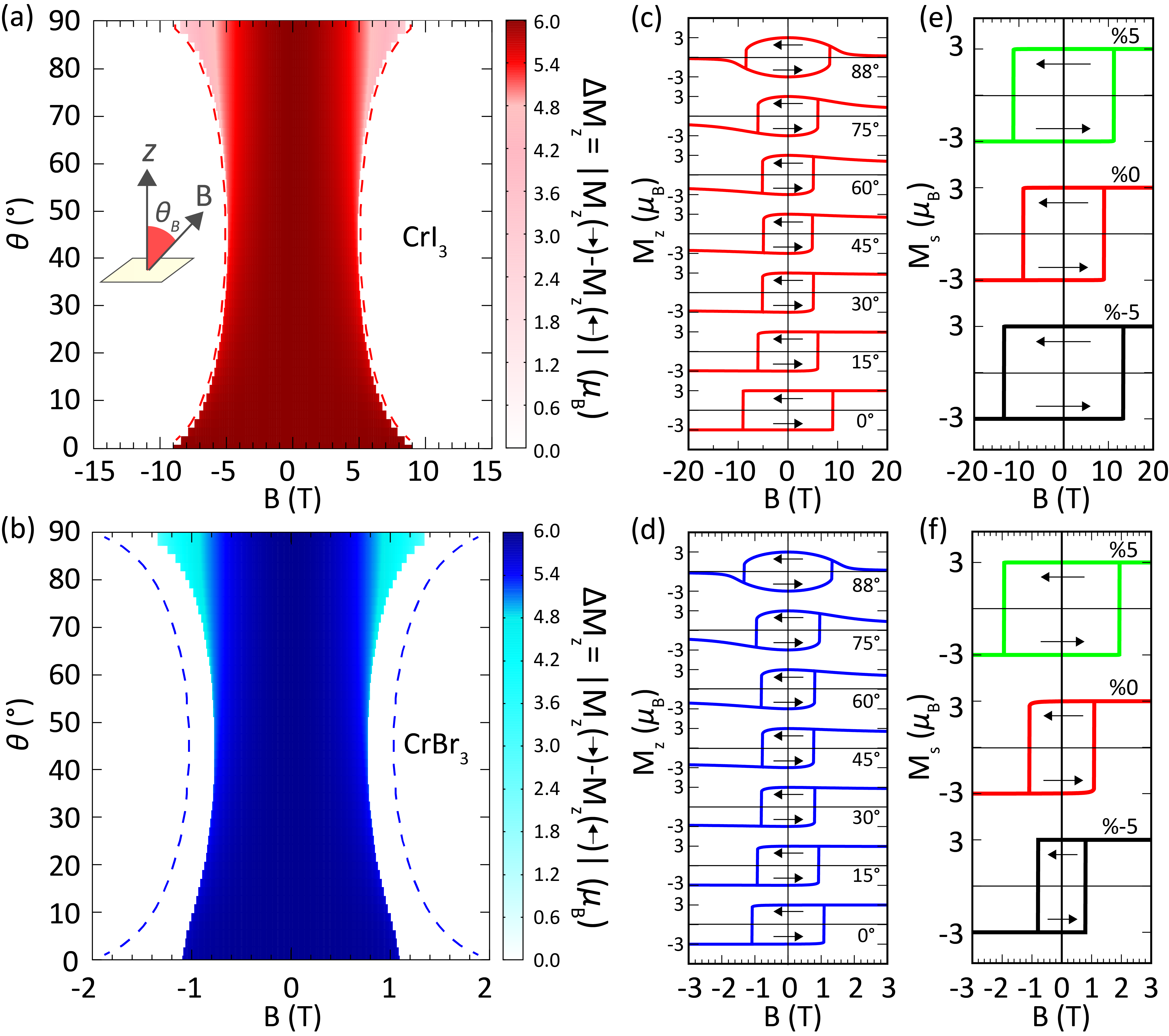
Finally, motivated by its accessibility by advanced magnetometry,kim2019micromagnetometry we calculated the hysteretic behavior of the monolayers under magnetic field tilted by angle from the -axis, for both CrI3 and CrBr3.
In the simulations, the spin system is initialized at high applied field, where all the spins are aligned to the magnetic field direction. The field is then looped in steps of T and T for CrBr3 and CrI3 respectively, where the magnetization is relaxed by time steps for each value of field. Dipole-dipole interactions have been included in the simulations. In Fig. 7(a,b), we show the obtained as a color-map plot where shades of red (CrI3) and blue (CrBr3) color show the deviation of hysteresis loop from the rectangular shape. In Figs. 7 (c) and (d), we plot the corresponding hysteresis curves for selected tilt angles of the applied magnetic field. One clearly sees that hysteresis loops evolve from sharp rectangular to an oval form as the tilt angle is increased, as was recently shown experimentally by Kim et al. for the case of monolayer CrBr3.
In absence of dipolar interactions, the behavior of magnetic spins in external field is captured by minimization of the energy , where is the energy associated with the magnetic field, and grows linearly with increasing . The value of the critical, ’switching’ field for the given angle , scaled to the switching field for [] is then analytically obtained from the condition that the energy extrema coalesce, leading to equation
| (3) |
This functional dependence of critical field on the tilt angle perfectly reproduces the numerically calculated switching field, shown by dashed lines in Figs. 7(a,b). Notably, the switching field in absence of dipolar interactions () shows symmetric behavior with respect to . However, with dipolar interactions included, that symmetry is broken in case of CrBr3, and switching field for becomes significantly lower than for . The latter was indeed validated experimentally, in Ref. kim2019micromagnetometry, . However, dipolar interactions cause no changes in the critical field of CrI3 for any , which is another important distinction between two materials that could be verified by Hall micromagnetometry.
One should however note that in our considerations we do not involve finite size effects nor demagnetization, or temperature fluctuations, likely playing an important role in experiment (next to the ever-present defects in the monolayers, that can facilitate magnetic reversal locally). Our simulations explore primarily the effect of the microscopic parameters on the apparent magnetic behavior, with a goal of capturing the intrinsic differences between CrI3 and CrBr3. As a consequence, the switching fields in our simulations are significantly larger than experimentally reported values of 0.15T huang2017layer for CrI3 and 0.03Tkim2019micromagnetometry for CrBr3, for . Having said that, our simulations capture the large ratio between switching fields of the two monolayer materials (approximately 8 and 5 for simulation and experiment, respectively).
To feature yet another experimentally verifiable difference between monolayer CrI3 and CrBr3, we also calculated the hysteresis curves for the strained magnetic monolayers under out-of-plane magnetic field. We recall that MAE and SIA, plotted in Fig. 4(b,c) and Fig. 5(c), respectively, showed distinctively different behavior in two materials when under strain. As shown in Figs. 7 (e) and (f), the width of the hysteresis loop strongly changes with the strain. However, while the switching magnetic field of monolayer CrI3 increases under both compressive and tensile strain, the switching field of monolayer CrBr3 is reduced by compressive strain while the tensile strain increases the switching field stronger than was the case in CrI3 (measured with respect to the unstrained case). This behavior can thus be mapped on the behavior of exchange anisotropy and SIA under strain, all rooted in the known difference in spin-orbit coupling between the two materials.
IV Conclusions
We compared two of the very first ferromagnetic 2D materials, monolayer CrI3 and CrBr3, belonging to the same chromium-trihalide CrX3 family. Although very similar qualitatively in structural and electronic properties (with some quantitative differences such as lattice constant, bond length, and electronic band gap), these materials exhibit strong differences in magnetic properties and their behavior with external stimuli. We attribute these differences to the spin-orbit interaction not only on ligand atoms (X=I, Br) and but also at the bonding orbitals. We show that the energetic preference of the direction of spin of a ligand directly depends on the bonding direction of that particular ligand relative to the spin direction. That means spin-orbit coupling (SOC) energy contribution of an individual ligand can be predicted qualitatively via its coordination and spin direction.
We also present the magnetic exchange parameters for the two monolayers. The mean exchange interaction in CrI3 is larger that one of CrBr3, but the difference between their out-of-plane anisotropy values () as well as between single-ion anisotropies (SIA) are more than significant. We also clearly demonstrated that the origin of both the out-of-plane anisotropy and the SIA is the spin-orbit interaction, since our analogous analysis without SOC yielded no exchange anisotropy and no SIA.
By applying biaxial strain, we revealed further differences between monolayer CrI3 and CrBr3. The strain mostly changes the Cr-X-Cr angle instead of the bond length. That results in significant structural distortion of the octahedral units of the monolayers. Magnetic anisotropy energy (MAE) of CrI3 increases under either compressive and tensile strain while MAE of CrBr3 linearly increases (decreases) under increasing tensile (compressive) strain. This difference in the variation of MAE is reflected on the corresponding changes in the out-of-plane anisotropy of the exchange parameters and the SIA parameter. With such differences in obtained parameters for the two materials, we calculated the temperature-dependent magnetization for pristine and the strained monolayers, to reveal much stronger variation with strain of in CrI3 than in CrBr3. The found critical exponent of our data places CrBr3 virtually in the 3D regime, owing to its low out-of-plane anisotropy, contrary to the strong 2D character of CrI3.
For facilitated direct observation of the reported differences between monolayer chromium-trihalides, and as a direct probe of their magnetic anisotropy, fostered by spin-orbit coupling, we also calculated the behavior of hysteretic magnetization loops as a function of the tilt angle between the applied field and the monolayer plane. We revealed that magnetic behavior of CrBr3 is far more affected by dipolar interactions than is the case in CrI3, but also that the behavior of the switching field with strain is entirely different in two materials, analogously to previously observed differences in MAE and SIA as a function of strain. These findings are yet another proof that even subtle differences in atomic contributions to spin-orbit coupling between two akin materials can lead to rather dissimilar magnetic properties, and can be broadly tuned by gating, straining and heterostructuring of the 2D material. Although sourced in properties at atomistic scale, these differences can clearly manifest in macroscopic observables and are verifiable experimentally (owing to e.g. recent advances in Hall magnetometry). Therefore, tailored solutions for spatially engineered spin-orbit coupling in magnetic monolayers present an attractive roadmap towards advanced spintronic and magnonic nanocircuitry.
Acknowledgements.
This work was supported by the Research Foundation-Flanders (FWO-Vlaanderen) and the Special Research Funds of the University of Antwerp (TOPBOF). The computational resources and services used in this work were provided by the VSC (Flemish Supercomputer Center), funded by Research Foundation-Flanders (FWO) and the Flemish Government – department EWI.References
- (1) J.-G. Park, Journal of Physics: Condensed Matter 28, 301001 (2016).
- (2) J.-U. Lee, S. Lee, J. H. Ryoo, S. Kang, T. Y. Kim, P. Kim,C.-H. Park, J.-G. Park, and H. Cheong, Nano letters 16, 7433 (2016).
- (3) X. Wang, K. Du, Y. Y. F. Liu, P. Hu, J. Zhang, Q. Zhang,M. H. S. Owen, X. Lu, C. K. Gan, P. Sengupta,et al., 2D Materials 3, 031009 (2016).
- (4) M.-W. Lin, H. L. Zhuang, J. Yan, T. Z. Ward, A. A. Puret-zky, C. M. Rouleau, Z. Gai, L. Liang, V. Meunier, B. G.Sumpter,et al., Journal of Materials Chemistry C 4, 315 (2016).
- (5) B. Huang, G. Clark, E. Navarro-Moratalla, D. R. Klein,R. Cheng, K. L. Seyler, D. Zhong, E. Schmidgall, M. A.McGuire, D. H. Cobden,et al., Nature 546, 270 (2017).
- (6) C. Gong, L. Li, Z. Li, H. Ji, A. Stern, Y. Xia, T. Cao,W. Bao, C. Wang, Y. Wang et al., Nature 546, 265 (2017).
- (7) M. Gibertini, M. Koperski, A. Morpurgo, and K. Novoselov, Nature nanotechnology 14, 408 (2019).
- (8) M. Kim, P. Kumaravadivel, J. Birkbeck, W. Kuang, S. G.Xu, D. Hopkinson, J. Knolle, P. A. McClarty, A. Berdyu-gin, M. B. Shalom et al., Nature Electronics 2, 457 (2019).
- (9) D. R. Klein, D. MacNeill, Q. Song, D. T. Larson, S. Fang, M. Xu, R. A. Ribeiro, P. C. Canfield, E. Kaxiras, R. Comin et al., Nature Physics 15, 1255 (2019).
- (10) M. Bonilla, S. Kolekar, Y. Ma, H. C. Diaz, V. Kalappattil, R. Das, T. Eggers, H. R. Gutierrez, M.-H. Phan, and M. Batzill, Nature nanotechnology 13, 289 (2018).
- (11) Z. Fei, B. Huang, P. Malinowski, W. Wang, T. Song,J. Sanchez, W. Yao, D. Xiao, X. Zhu, A. F. May et al., Nature materials 17, 778 (2018).
- (12) D. J. O’Hara, T. Zhu, A. H. Trout, A. S. Ahmed, Y. K.Luo, C. H. Lee, M. R. Brenner, S. Rajan, J. A. Gupta,D. W. McComb et al., Nano letters 18, 3125 (2018).
- (13) N. D. Mermin and H. Wagner, Physical Review Letters 17, 1133 (1966).
- (14) T. Moriya, Phys. Rev. 120, 91 (1960).
- (15) J. Liu, Q. Sun, Y. Kawazoe, and P. Jena, Physical Chem-istry Chemical Physics 18, 8777 (2016).
- (16) W.-B. Zhang, Q. Qu, P. Zhu, and C.-H. Lam, Journal ofMaterials Chemistry C 3, 12457 (2015).
- (17) L. Webster and J.-A. Yan, Phys. Rev. B 98, 144411 (2018).
- (18) D. Torelli, K. S. Thygesen, and T. Olsen, 2D Materials 6, 045018 (2019).
- (19) 19 D. Torelli and T. Olsen, 2D Materials 6, 015028 (2018).
- (20) T. Olsen, MRS Communications 9, 1142 (2019).
- (21) M. Rassekh, J. He, S. F. Shayesteh, and J. J. Palacios, Computational Materials Science 183, 109820 (2020).
- (22) M. Pizzochero, Journal of Physics D: Applied Physics 53, 244003 (2020).
- (23) M. Pizzochero and O. V. Yazyev, The Journal of Physical Chemistry C 124, 7585 (2020).
- (24) J. L. Lado and J. Fernández-Rossier, 2D Materials 4, 035002 (2017).
- (25) C. Xu, J. Feng, H. Xiang, and L. Bellaiche, npj Computational Materials 4, 1 (2018).
- (26) L. Chen, J.-H. Chung, T. Chen, C. Duan, A. Schneidewind,I. Radelytskyi, D. J. Voneshen, R. A. Ewings, M. B. Stone,A. I. Kolesnikov, B. Winn, S. Chi, R. A. Mole, D. H. Yu,B. Gao, and P. Dai, Phys. Rev. B 101, 134418 (2020).
- (27) D.-H. Kim, K. Kim, K.-T. Ko, J. Seo, J. S. Kim, T.-H.Jang, Y. Kim, J.-Y. Kim, S.-W. Cheong, and J.-H. Park,Phys. Rev. Lett. 122, 207201 (2019).
- (28) H. Xiang, C. Lee, H.-J. Koo, X. Gong,and M.-H.Whangbo, Dalton Transactions 42, 823 (2013).
- (29) D. Sabani, C. Bacaksiz, and M. V. Milošević, Phys. Rev. B 102, 014457 (2020).
- (30) G. Kresse and J. Hafner, Phys. Rev. B 47, 558 (1993).
- (31) G. Kresse and J. Furthmüller, Computational materials science 6, 15 (1996).
- (32) G. Kresse and J. Furthmüller, Phys. Rev. B 54, 11169 (1996).
- (33) J. P. Perdew, K. Burke, and M. Ernzerhof, Phys. Rev. Lett. 77, 3865 (1996).
- (34) S. Steiner, S. Khmelevskyi, M. Marsmann, and G. Kresse,Phys. Rev. B 93, 224425 (2016).
- (35) S. Grimme, Journal of Computational Chemistry 27, 1787 (2006).
- (36) G. Henkelman, A. Arnaldsson, and H. Jónsson, Compu-tational Materials Science 36, 354 (2006).
- (37) S. L. Dudarev, G. A. Botton, S. Y. Savrasov, C. J.Humphreys, and A. P. Sutton, Phys. Rev. B 57, 1505 (1998).
- (38) N. Sivadas, M. W. Daniels, R. H. Swendsen, S. Okamoto,and D. Xiao, Physical Review B 91, 235425 (2015).
- (39) B. L. Chittari, Y. Park, D. Lee, M. Han, A. H. MacDonald,E. Hwang, and J. Jung, Physical Review B 94, 184428 (2016).
- (40) P. Jiang, C. Wang, D. Chen, Z. Zhong, Z. Yuan, Z.-Y. Lu,and W. Ji, Phys. Rev. B 99, 144401 (2019).
- (41) G. P. Müuller, M. Hoffmann, C. Dißelkamp, D. Schüurhoff,S. Mavros, M. Sallermann, N. S. Kiselev, H. Jónsson, andS. Blügel, Phys. Rev. B 99, 224414 (2019).
- (42) P. Li, C. Wang, J. Zhang, S. Chen, D. Guo, W. Ji, and D. Zhong, Science Bulletin (2020).
- (43) W. Chen, Z. Sun, Z. Wang, L. Gu, X. Xu, S. Wu, andC. Gao, Science 366, 983 (2019).
- (44) R. Albaridy, A. Manchonand, and U. Schwingenschlögl, J. Phys.: Condens. Matter 32 355702 (2020).
- (45) Y. Liu and C. Petrovic, Phys. Rev. B 97, 014420 (2018).
- (46) S. Bramwell and P. Holdsworth, Journal of Physics: Condensed Matter 5, L 53 (1993).