Diffuse laser illumination for Maxwellian view Doppler holography of the retina
Abstract
We present the benefits of using diffuse illumination in laser holography for ophthalmic applications. Integrating a diffusing element introduces angular diversity in the optical radiation and reduces spatial coherence, effectively distributing the illumination beam’s energy across the focal plane of the eyepiece. This configuration allows for an expanded field of view in digitally computed retinal images, as the eyepiece can be positioned closer to the cornea to achieve a Maxwellian view of the retina without compromising ocular safety. By avoiding the formation of a laser hot spot near the cornea, diffuse illumination facilitates easier compliance with American and European safety standards for ophthalmic devices. Importantly, this approach does not introduce any adverse effects on digitally computed Doppler images.
I Introduction
Optical holography methods increasingly leverage the use of laser radiation for coherent, phase-resolved computational imaging in ophthalmology from camera recordings of interference patterns of the light backscattered by the retina beating against a separate reference beam. This imaging scheme is highly suited to the computation of local optical Doppler contrasts [1] and permits imaging of both the anterior and posterior segments of the eye from the same recorded data set of raw interferograms [2]. Yet for the particular case of retinal imaging, extending the field of view of the computed images used to be avoided to prevent high local irradiance of the cornea beyond permissible laser exposure recommendations from American and European ophthalmic safety norms. In previous work, the eye was typically illuminated with 2 mW or less of constant exposure to near infrared laser light focused in front of the cornea, at a distance either equal to or greater than the eye focal length, depending on the desired field of view [2]. When focusing exactly in the eye front focal plane, the obtained field of view has, at most, a similar extension for the iris and retina. The iris acts as an image field diaphragm instead of an aperture stop, which prevents wide-angle imaging. For instance, the construction of a full image of the posterior pole of the retina (the portion centered on the macula that includes the optic nerve) required image rendering and stitching from numerous sequential acquisitions [3].
In this letter, we report on the use of diffuse laser illumination to increase the field of view of digital holography up to a Maxwellian view of the retina, which consists in illuminating and collecting light from a large retinal area by a converging beam focused near the eye’s nodal point, approximately 17 mm in front of the retina [4]. The proposed optical arrangement avoids the need for eye dilation for wide-field holographic imaging of the retina.
II Experimental setup


The experimental setup is based on a Mach-Zehnder inline interferometer (Fig. 1). The near-infrared radiation from a diode laser (Thorlabs FPV852P, wavelength : = 852 nm, model 40750) is split 10% - 90% respectively into linearly-polarized reference and illumination arms, emerging from polarization-maintaining fibers (Thorlabs PM780-HP, numerical aperture : NA 0.12). The illumination beam passes through an engineered diffuser (Thorlabs ED1-C20-MD SM1-Threaded Mount, diameter : 1”, 20° circle tophat engineered diffuser) and an eyepiece made of two biconvex lenses of 60 mm focal length each, with an effective focal length of 33 mm. Two cameras are used to record interferograms of the cross-polarized backscattered light component with respect to illumination. One is used for real-time preview (Adimec Quartz Q-2HFW-Hm/CXP-6-0.5 camera, pixel pitch : 12 m), and another one is used for offline image rendering (Ametek Phantom V2012, frame rate: 35 kHz, pixel pitch : m, frame size : pixels). The latter is used for all the interference pattern measurements used for image rendering. The retina of a volunteer is illuminated with a continuous-wave laser beam focused through the eyepiece in three distinct layouts sketched in Fig. 2 :
-
•
the illumination beam was focused at the natural focus point of the eye (Fig. 2), in the absence of diffuser.
-
•
the illumination beam waist was homogeneously spread by introduction of a diffuser. No change of relative position between the cornea and the lenses of the eyepiece was made (Fig. 2),
-
•
the cornea-to-eyepiece distance was reduced in the presence of the diffuser in order to increase the field of view (Fig. 2).
Informed consent was obtained from the subject, experimental procedures adhered to the tenets of the Declaration of Helsinki, study authorization was obtained from the appropriate local ethics review boards - Personal Protection Committees (CPP Sud-Est III: 2019-021B) and National Agency for the Safety of Medicines and Health Products (ANSM No. IRDCB : 2019-A00942-55); the clinical trial was registered under the reference NCT04129021. The patient positioning was monitored by real-time computation and visualization of clutter-free inline digital holograms of the eye fundus from an input stream of 16-bit, 1024-by-1024-pixel interferograms recorded at 800 frames per second with the Adimec Quartz camera. This was done by Fresnel transformation and principal component analysis of stacks of 64 consecutive holograms [5], with the digital hologram streaming software holovibes.
III Optical configuration. Interference pattern measurement
Fig. 4 illustrates the optical configuration used for interference pattern measurement, from which image rendering is made. The focal length of one imaging lens is 60 mm (Thorlabs LB1723-B; N-BK7 bi-convex lens, diameter : 2”, = 60.0 mm, Anti-reflective coating: 650-1050 nm). The doublet has a focal length of 33 mm, for a distance between its composing lenses of about 1 cm, according to Gullstrand’s formula. The optical conjugate of the sensor plane is set in front of the cornea, at a distance 33 mm from the center of the doublet. At this distance, the sensor-to-cornea magnification ratio is . To calculate the sensor to retina magnification ratio of the digitally rendered image, the optical system of the eye must be considered. In the thin lens approximation (first-order properties of the optical system of the eye), light rays passing close to the optical center are not deflected. The sensor to retina magnification ratio of the digitally rendered image can therefore be estimated. For an average axial length of the eye of 25 mm, . The pixel pitch of the rendered image with the angular spectrum propagation method for numerical reconstruction distances from the cornea to the retina has a constant value for a given magnification ratio. The image pitch in the iris and the retina plane are , respectively. The lateral field of view of the rendered image in the iris and retina planes are and respectively; the former typically fits within the normal pupil size in adults which varies from 2 to 4 mm in diameter in bright light to 4 to 8 mm in the dark [6]. The lateral field of view at the iris plane is of the order or smaller than the typical iris aperture, whereas the field of view in the eye fundus is maximized. This configuration can be adapted by changing : 1- the cornea-to-eyepiece distance, 2- the focal length of the eyepiece, 3- the sensor-to-eyepiece distance.

IV Digital image rendering
Offline computation and registration of high-quality Doppler images from 12-bit, 768-by-768-pixel interferograms recorded at 35,000 frames per second by the Ametek Phantom V2511 camera was done by angular spectrum propagation [1], singular value decomposition filtering and short-time Fourier transformation [3] with the image rendering software holowaves. Numerical rendering of Doppler fundus images from the broad fluctuation frequency band between 2 kHz and 17 kHz and from the high frequency band from 12 kHz to 17 kHz are displayed in Fig. 3. These images were computed from raw interferograms acquired in the three layouts of Fig. 2.
V Radiometric measurements and irradiance estimation
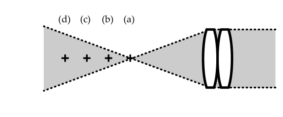
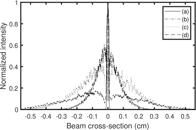
The maximum allowable exposure of the eye to optical radiation is dictated by power areal density (irradiance) limits. To estimate the irradiance of the optical illumination of both segments of the eye, we measure cross-section distributions and profiles, and the total power of the near-infrared laser beam used for eye illumination.


V.1 Optical power
The measurements of the optical power of the illumination beam were carried out using a photodiode associated with a portable digital console for measuring optical power and energy (Thorlabs S121C & PM100D). The optical power of the laser beam was measured in the waist plane of the laser, over an active detection area of 9.7 mm 9.7 mm with an entrance aperture diameter of 9.5 mm.
V.2 Beam cross section
The irradiance distribution of the optical radiation at the cornea is evaluated with and without diffuser in Fig. 6 and Fig. 5, respectively. The measurements were taken at different distances from the focal plane to evaluate the beam cross-section distribution with the bare sensor array of a camera (XIMEA XIQ model MQ042xG-CM, 2048-by-2048 pixel frame; pixel pitch : 5.5 m). The horizontal cross section profiles in Fig. 5 and Fig. 6, averaged over 165 microns vertically around the center of the distribution describe the radial distribution of the light intensity around the cornea. A quantitative irradiance map was assessed at the waist of the laser beam in diffuse illumination configuration in Fig. 7, from the measured irradiance distribution, for a total illumination power of 22 mW.


VI European safety limits standard
The European standard ISO 15004-2:2007 specifies fundamental requirements for optical radiation safety for ophthalmic instruments and is applicable to all ophthalmic instruments that direct optical radiation into or at the eye and for which there is a specific light hazards requirement section. It is also applicable to all new and emerging ophthalmic instruments that direct optical radiation into or at the eye. Ophthalmic instruments are classed into either group 1 or group 2 in order to distinguish instruments that are non-hazardous from those that are potentially hazardous. The proposed instrument can belong to group 1 as long as it complies with the maximum permissible exposure of the anterior and posterior segments, reported hereafter.
A diffuse laser beam is focused in front of the eye and then transmitted inside the eye, according to Fig. 2. When the anterior segment of the eye is in the focal region of the illuminating beam (Fig. 2), wide-field Maxwellian view of the retina [4] is made possible. Under the eye illumination conditions illustrated in Fig. 2 and Fig. 2, the smallest of the retina and corneal surfaces exposed to the light beam is that of the cornea. Beam cross-section measurements and radial illumination profiles are plotted in Fig. 6, for a 33 mm effective focal length eyepiece.
VI.1 MPE of the retina (ISO)
According to the ISO 15004-2 (2007) standard [8], in order to avoid thermal hazard, in conditions of continuous-wave, monochromatic illumination of the retina, the maximum permissible exposure (MPE : irradiance in ) weighted by the thermal hazard factor must not exceed the value (Eq. 5.4.1.6.a from Table 2 in [8])
| (1) |
where and are the monochromatic irradiance, and the thermal hazard weighting factor. For an illumination wavelength between 770 nm and 1400 nm, the weighting factor varies monotonously between and (Table A.1 in [8]). The value is chosen for the calculations. From Eq. 7, the maximum permissible exposure of the retina is . According to the ISO norm guidelines, this limit should be assessed in a local 0.03 mm-radius (-area) disc in the retina plane where the irradiance is maximum. Because of the high-contrast speckle illumination, it is safe to divide this irradiance value by a factor 2 ; hence .
The measurement of the illumination beam cross-section is done according to the procedure described in section V.2. The narrowest radial illumination distribution in Fig. 6 measures the minimum beam spread at its waist (line b); it is flat in its center within a disc of 1 mm of radius. Let’s consider that the total optical power limit should pass through a 1 mm-radius circular aperture of area . We have .
In diffuse Maxwellian illumination conditions, the actual beam cross section profile cannot be more narrow in the retina plane than the distribution in Fig. 6 that is measured at the beam waist plane, at position (b) in Fig. 6. The irradiance distribution in this plane at each pixel location (pitch : , pixel area : ) is assessed for a total input power of 22 mW. This total impinging optical power limit of 22 mW distributed according to Fig. 6 results in an irradiance map reported in Fig. 7. The maximum local irradiance in the map is about .
That maximum local irradiance is assessed over an area of one pixel, which is smaller than the one mentioned by the ISO norm for the retina (), so that exposure compliance with the norm is always ensured. Hence, the highest irradiance received on a 0.03 mm-diameter disk at the level of the retina satisfies , for a total illumination power = 22.0 mW. This limit is assessed for the optical configurations sketched in Fig. 2 and Fig. 2.
VI.2 MPE of the anterior segment (ISO)
VI.2.1 Illumination of the cornea and crystalline lens
According to Eq. 5.4.1.4 in table 2 of the ISO 15004-2 (2007) standard [8], the irradiance must be evaluated by taking the average of the highest localized radiation power received on a disc 1 mm in diameter at the level of the cornea, i.e. an area of , and should not exceed . The narrowest radial illumination distribution in Fig. 6 measures the minimum beam spread impinging on the cornea; it is flat in its center for more than 1 mm. A luminous power = 2.5 mW distributed spatially according to this distribution is of the order of a uniform irradiance integrated on a disk of 2.0 mm radius and area, i.e. we can estimate the irradiance : . Under these conditions, the highest average surface power of radiation received on a disk of 1 mm in diameter at the level of the anterior segment is , for a total illumination power = 2.5 mW. This limit is for the optical configurations sketched in Fig. 2, Fig. 2, and Fig. 2.
VI.2.2 Convergent illumination of the anterior segment
The maximum exposure limit for convergent illumination of the anterior segment of the eye is given by Eq. 5.4.1.5 in table 2 of the ISO 15004-2 (2007) standard [8]. The maximum permissible irradiance must be evaluated by taking the unweighted average of the highest localized radiation power received on a disc 1 mm in diameter at the level of the cornea. The irradiance of the cornea and of the crystalline lens within a 1 mm aperture shall not exceed .
Let’s consider that the total optical power limit should pass through this 1 mm-diameter aperture of area . In order to mitigate the issue of the presence of any local speckle variation - i.e. constructive or destructive interference, this limit value is divided by 2. This sets the optical power limit to . The narrowest measured radial illumination beam profile in Fig. 6 defines the minimum possible beam extension, which can be minimized by a disc of 2 mm-diameter. A total luminous power = 15.7 mW distributed spatially with a flat distribution bounded by this disc results necessarily in an irradiance much lower than .
A flat illumination of total power concentrated within a disk of 2.0 mm-diameter and area , defines an irradiance level which complies with the MPE of the anterior segment of the eye. The highest irradiance received on a 1 mm-diameter disk at the level of the anterior segment satisfies , for a total illumination power = 15.7 mW. This limit is for the optical configuration sketched in Fig. 2.
VII American safety limits standards 2014
The American standard ANSI Z136.1-2014 specifies fundamental requirements for optical radiation safety for ophthalmic instruments. Within the retinal hazard region of the optical spectrum, for wavelengths from 400 nm to 1400 nm, optical sources are considered either point or extended. Point sources subtend a visual angle less than or equal to = 1.5 mrad (section 8.1 in [9]). Extended sources subtend an angle greater than . The MPEs for extended sources are listed in Table 5e and Table 5f in [9]. The MPEs are expressed relative to the limiting aperture area and, therefore, a limiting aperture or limiting cone angle shall be used for measurements or calculations with all MPEs. The limiting aperture is the maximum circular area over which irradiance or radiant exposure shall be averaged. (section 8 in [9]).
VII.1 MPE for a point source (ANSI 2014)
The maximum permissible exposure (MPE, in ) for a point source ocular exposure for an exposure duration from 10 to 30,000 seconds is
| (2) |
(from Table 5c in [9]), where the correction factor for radiation wavelengths between 700 and 1050 nm is
| (3) |
(from Table 6a in [9]), where is the radiation wavelength expressed in nm. For = 852 nm, MPE . This value for the MPE is given only for comparison purposes with the relevant MPEs for the retina and the cornea calculated for an extended source hereafter.
VII.2 MPE of the retina for an extended source (ANSI 2014)
The maximum permissible exposure of the retina (MPE, in ) for an extended source ocular exposure for an exposure duration from (Eq. 6) to 30,000 seconds is
| (4) |
(from Table 5f in [9]), where the value of is given by Eq.6, the correction factor for radiation wavelengths between 700 and 1050 nm is given by Eq.3, and the correction factor for an extended source is
| (5) |
(from Table 6b in [9]), where the angular parameters , , and are the source angle (expressed in mrad), and the lower and upper bounds mrad, mrad. The angular subtense, , is based on an effective Gaussian image at 1/e of peak irradiance points, and , are determined from the equations in Table 6b and Table 6c in [9]. When computing , dimensions less than are set equal to , and values greater than 100 mrad are set equal to 100 mrad. The angular parameter estimated from Fig. 6 by using a 4.0 mm distance at 1/e of peak irradiance points of the narrowest effective Gaussian irradiance distribution in Fig. 6, and a typical axial length of the eye of 25 mm : ; hence . The correction time for an extended source is
| (6) |
(from Table 6b in [9]), where the angular parameter is set to the upper limit value mrad because diffuse laser illumination satisfies the required conditions for an extended source; hence = 100 s. For a radiation wavelength of = 852 nm, the maximum permissible exposure of the retina calculated from Eq. 4, is . In the most restrictive case (i.e. minimum extent of the irradiance at the retina), this value is reached outside of Maxwellian view conditions, where the total optical power would be distributed according to the narrowest irradiance profile from Fig. 6 within the retina, which is approximated by a uniform irradiance integrated on a disk of 1.0 mm radius and area. In that case, .
As recommended in [9], the MPE for sources larger than are based on retinal irradiance or retinal radiant exposure, yet additional MPE of the anterior segment guidelines for the Maxwellian view of the retina are given specifically and analyzed hereafter.
VII.3 MPE of the anterior segment for an extended source (ANSI 2014)
The irradiation of the anterior segment in Maxwellian view is the subject of additional guidance (section 8.3.4 in [9]) : irradiation of large retinal areas (“Maxwellian View”) may result in high irradiances of the anterior segment of the eye. If the iris is not exposed, the irradiance of the cornea and of the crystalline lens within a 1 mm aperture shall not exceed for an exposure time 10 s, and for 10 s. The most restrictive irradiance limit is . This limit is the same as the one treated in section VI.2.2 for the ISO norm, which gives the same estimated value for MPE of the cornea : , reached for a total laser power of 15.7 mW impinging on the cornea.
VII.4 MPE of the iris for an extended source (ANSI 2014)
Exposure of the iris shall not exceed five times the MPE’s of the skin (see 8.4 and Table 7). For hazard analysis of the iris, the limiting aperture for corneal exposures for wavelengths 1200 nm to 1400 nm (see Table 8) shall be used for all wavelengths
VIII American Safety Limits Standards 2021
The American standard ANSI Z136.8-2021 specifies fundamental requirements for optical radiation safety for ophthalmic instruments. In this updated version of the 2014 standards, it is not distinguished anymore points from extended optical sources. The MPEs for Group 1 continuous wave radiation sources are listed in Table 2 (paragraph 5.4.1) in [10], relatively to the limiting aperture area expressed as the maximum circular area over which irradiance or radiant exposure shall be averaged like in the previous standard [9].
VIII.1 MPE of the retina (ANSI 2021)
According to the ANSI Z136.8-2021 standard [10], in order to avoid thermal hazard, in conditions of continuous-wave, monochromatic illumination of the retina, the maximum permissible exposure (MPE : irradiance in ) weighted by the thermal hazard factor must not exceed the value (Eq. 5.4.1.6 from Table 2 in [10]).
| (7) |
where and are the monochromatic irradiance, and the thermal hazard weighting factor (Tables A.1 in [10]). The value is chosen for the calculations (wavelength of 852 nm). This value of is the only difference between the ANSI 2021 and the ISO standards, then we apply the same calculation procedure as in section VI.1.
The maximum permissible exposure of the retina is . A factor 1/2 is applied on this limit because of the high-contrast speckle illumination, to obtain . One consider that the total optical power limit should pass through a 1 mm-radius circular aperture of area . We have .
In diffuse Maxwellian illumination conditions, we assess the pixel irradiance for the narrowest profile, with a total input power of 20.3 mW. This results in the same irradiance map distribution as reported in Fig. 7, but with a maximum local irradiance of . Hence, the highest irradiance received on a 0.03 mm-diameter disk at the level of the retina is , for a total illumination power = 20.3 mW.
VIII.2 MPE of the anterior segment (ANSI 2021)
The maximum exposure limit for the anterior segment for our wavelength of 852 nm is given by Eq. 5.4.1.5 in table 2 of the ANSI Z136.8-2021 standard [10]. This limit only applies to instruments that in normal use irradiate the eye with beams that have a diameter of 2 mm or less at any point. Given the measured illumination pattern reported in Fig. 6, one can assume that all the optical radiation passes through a 2 mm-diameter circular aperture at the pupil plane. This assumption sets an upper bound to the real irradiance at the anterior segment because the real optical focus spot is wider than a 2 mm-diameter circular aperture. Being the same limit as in section VI.2.2 (irradiance within a 1 mm aperture taken at any plane in the anterior segment must not exceed ), calculations and results are the same. In that conditions, the highest irradiance received on a 1 mm-diameter disk at the level of the anterior segment is , for a total illumination power = 15.7 mW.
The Group 1 continuous wave instrument limit in Eq. 5.4.1.4 of Table 2 in the ANSI Z136.8-2021 standard [10] is not applicable, as our operating wavelength (852 nm) falls outside the specified range (915–2500 nm).
IX Discussion
In the absence of diffuser (Fig. 5), the illumination pattern in the neighborhood of the beam focal plane has a very energetic central bright spot (hot spot, Fig. 5) that should be removed to comply with both ISO and ANSI exposure safety norms. The use of an engineered diffuser that scatters all the input laser beam and filters non-diffracted light (Fig. 6) has several benefits : the issue of the presence of a hot spot is alleviated and the cornea-to-eyepiece distance can be reduced to increase the lateral field of view of the reconstructed eye fundus image. The field of view of the eye fundus image for a given iris aperture is much wider with than without diffuser, as shown in Fig. 3.
The quantitative estimates for the maximum permissible exposure (MPE) of the eye to a continuous-wave, extended near infrared laser source by Maxwellian-view holography with diffuse illumination, from our interpretation of European and American safety standards, are the following :
-
•
MPE of the retina (ISO 15004-2:2007) : maximum local irradiance of over a 0.03 mm-radius disc for a total laser power of 22.0 mW impinging on the retina.
-
•
MPE of the cornea and the crystalline lens (ISO) : , reached for a total laser power of 2.5 mW impinging on the cornea.
-
•
MPE of the anterior segment (ISO 15004-2:2007) for convergent illumination : , reached for a total laser power of 15.7 mW impinging on the cornea.
-
•
MPE of the retina (ANSI Z136.1-2014) : , reached for a total laser power of 6.2 mW impinging on the retina.
-
•
MPE of the cornea (ANSI Z136.1-2014) : , reached for a total laser power of 15.7 mW impinging on the cornea.
-
•
MPE of the retina (ANSI Z136.8-2021) : , reached for a total laser power of 20.3 mW impinging on the retina.
-
•
MPE of the cornea (ANSI Z136.8-2021) : , reached for a total laser power of 15.7 mW impinging on the cornea.
In the particular case of focused light impinging on the retina, i.e. for small-field retinal imaging, the proposed diffuse laser illumination scheme will prevent the formation of a laser hotspot in the posterior segment of the eye, so that the irradiance received by the retina stays compliant with safety limitations. In that regard, diffuse illumination acts as and improves the function of the long multimode fiber with a small core used to reduce the spatial coherence of the laser to image the cornea without causing risk to the retina [11]. That is highly valuable for high resolution retinal imaging configurations, because it decreases dramatically the local laser irradiance, and hence circumvents the issue of viewing a laser from within a collimated beam that produces a small ( 20 to 30 m) or nearly diffraction-limited retinal image, which will be nearly a point source, and subject to restrictive guidelines regarding maximum permissible exposure, listed in Table 5a, Table 5b, Table 5c, and Table 5d in [9]. Thorough investigation of high resolution laser Doppler imaging of the retina with diffuse illumination will be the subject of another study.
The proposed optical arrangement sketched in Fig. 1 and Fig. 4 can be used effectively for Maxwellian view (wide-field) holography of the human retina. Eye dilation is usually rendered unnecessary for imaging the posterior pole of the retina.
-
•
To ensure full compliance with the European standard ISO 15004-2:2007, we recommend limiting the optical power in the diffuse illumination setup for Doppler holography to a maximum of 2.5 mW at a wavelength of 852 nm, measured at the focal plane of the eyepiece. This limit is imposed by the maximum permissible exposure of the cornea and crystalline lens highlighted in section VI.2.1.
-
•
To meet the requirements of the American standard ANSI Z136.1-2014, we suggest maintaining a maximum optical power of 6.2 mW at a wavelength of 852 nm in the diffuse illumination configuration for Doppler holography, measured at the focal plane of the eyepiece. This limit is imposed by the maximum permissible exposure of the retina highlighted in section VII.2.
-
•
To meet the requirements of the American standard ANSI Z136.8-2021, we suggest maintaining a maximum optical power of 15.7 mW at a wavelength of 852 nm in the diffuse illumination configuration for Doppler holography, measured at the focal plane of the eyepiece. This limit is imposed by the maximum permissible exposure of the anterior segment highlighted in section VIII.2.
X Conclusion
Diffuse laser illumination offers several key advantages in holographic imaging for ophthalmology:
-
•
Enhanced safety compliance: Meeting American and European safety standards for ophthalmic devices is simplified compared to traditional laser illumination. Diffuse illumination reduces the risk associated with a laser focal spot on the cornea or retina, making compliance with safety limits more achievable. The irradiance level remains within the maximum permissible exposure for both the cornea and retina, regardless of the distance between the cornea and the illumination focus plane. This flexibility improves eye safety, especially during patient positioning.
-
•
Expanded field of view: By positioning the illumination and imaging optics focus closer to the cornea, the computed field of view for retinal images can be increased, enabling a Maxwellian view of the retina without compromising safety.
-
•
No need for eye dilation: Diffuse illumination eliminates the need for eye dilation, even for full posterior pole imaging.
-
•
Uncompromized Doppler imaging: There is no negative impact on Doppler images of blood flow, preserving image quality and diagnostic accuracy.
The authors declare that the research was conducted in the absence of any commercial or financial relationship that could be construed as a potential conflict of interest.
XI ACKNOWLEDGEMENTS
This work was supported by the IHU FOReSIGHT (ANR-18-IAHU-01), the European Research Council, the Sesame program of the Region Ile-de-France (4DEye, ANR-10-LABX-65), and the French National research agency (ANR LIDARO).
References
- [1] L. Puyo, M. Paques, M. Fink, J.-A. Sahel, and M. Atlan. In vivo laser doppler holography of the human retina. Biomedical Optics Express, 9(9):4113–4129, Sep 2018
- [2] Puyo, Léo, Clémentine David, Rana Saad, Sami Saad, Josselin Gautier, José Alain Sahel, Vincent Borderie, Michel Paques, and Michael Atlan. ”Laser Doppler holography of the anterior segment for blood flow imaging, eye tracking, and transparency assessment.” Biomedical optics express 12, no. 7 (2021): 4478-4495.
- [3] Léo Puyo, Michel Paques, and Michael Atlan, Spatio-temporal filtering in laser Doppler holography for retinal blood flow imaging, Biomed. Opt. Express 11, 3274-3287 (2020)
- [4] Sliney, David, et al. ”Adjustment of guidelines for exposure of the eye to optical radiation from ocular instruments: statement from a task group of the International Commission on Non-Ionizing Radiation Protection (ICNIRP).” Applied optics 44.11 (2005): 2162-2176.
- [5] Puyo, Leo, Loic Bellonnet-Mottet, Antoine Martin, Francois Te, Michel Paques, and Michael Atlan. ”Real-time digital holography of the retina by principal component analysis.” arXiv preprint arXiv:2004.00923 (2020).
- [6] Robert H. Spector Clinical Methods: The History, Physical, and Laboratory Examinations 3rd edition, Chapter 58 : The pupils https://www.ncbi.nlm.nih.gov/books/NBK381/
- [7] William F Ganong and Kim E Barrett. Review of medical physiology, volume 22. McGraw-Hill Medical ^ eNew York New York, 2005.
- [8] AFNOR European Standard for Safe Use of Lasers ISO, 2007.
- [9] Laser Institute of America American National Standard for Safe Use of Lasers ANSI Z136.1-2014.
- [10] Laser Institute of America American National Standard for Ophthalmics – Light Hazard Protection for Ophthalmic Instruments Z80.36-2021.
- [11] Egidijus Auksorius, Dawid Borycki, and Maciej Wojtkowski, ”Multimode fiber enables control of spatial coherence in Fourier-domain full-field optical coherence tomography for in vivo corneal imaging,” Opt. Lett. 46, 1413-1416 (2021)