Development of Musculoskeletal Legs with Planar Interskeletal
Structures to Realize Human Comparable Moving Function
Abstract
Musculoskeletal humanoids have been developed by imitating humans and expected to perform natural and dynamic motions as well as humans. To achieve desired motions stably in current musculoskeletal humanoids is not easy because they cannot maintain the sufficient moment arm of muscles in various postures. In this research, we discuss planar structures that spread across joint structures such as ligament and planar muscles and the application of planar interskeletal structures to humanoid robots. Next, we develop MusashiOLegs, a musculoskeletal legs which has planar interskeletal structures and conducts several experiments to verify the importance of planar interskeletal structures.
I INTRODUCTION
The tendon-driven musculoskeletal humanoids [1], [2] which imitates a human body structure, have muscles around bone structures as actuators. Muskuloskeletal humanoids are designed as a model of human beings and expected to perform natural and dynamic motions as a human being can do. Benefits of human mimetic structures are, for example, ball joints that have no singularity and redundant muscles, which enables variable stiffness control. However, muscle route can dynamically change in the current musculoskeletal humanoids as each muscle expands and contracts. This change makes it challenging to maintain the sufficient moment arm of muscles in any posture. Therefore it is difficult to apply enough torque to joints to perform the desired motions in some postures. In this study, we focus on interskeletal structures, such as muscles and ligaments, which act over different skeletal structures to solve this problem.
Ligaments are the essential interskeletal structures which bond different skeletal structures like muscles, but they passively act with joints; on the other hand, muscles actively act. The primary function of ligaments is to make restrictions within joints and determine the relative direction of movements and the range of motion. Even when the muscles do not perform tension, ligaments act passively to joints, stabilize joints and prevent the joint dislocation [3]. In many robots, axle-bearing and joint angle limits are implemented as a rigid mechanism. These rigid joints restriction cannot handle impact force and often break irreversibly. Non-rigid hardware systems are required to realize joint structures that have an elastic and complex range of motion.
Previous researches on joint restriction using non-rigid materials are as follows, deformable membrane capsule for an open ball glenohumeral joint which restricts translational motion [4], the ligament which restricts joints movement in rolling surface [5] and anthropomorphic robotic hands that have silicon rubber sleeve ligaments [6]. The mechanism in [4] prevents dislocation by covering ball joints with rubber. This mechanism has a trade-off between the strength of rubber and the range of motion, and the deterioration of rubber can be inevitable. In [5], the bundle of fibers restricts joint movement in the knee to the rolling surface. This research only considers the two-dimensional movement, so this mechanism cannot handle the rotational movement of the knee. The robotic hand in [6] has achieved flexible manipulation by using ligaments and shows the importance of ligaments in human-robotic hand structures.
To restrict spherical joints non-rigidly, wires and sleeves with high strength in the pulling direction are considered effective. However, using wires in three-dimensional structures is hard because wires cannot maintain their path under various configurations and wires tend to be caught in rough mechanical structures such as ditches and protuberance. In [7], the planar muscles solved some of these problems, but the insufficient durability in the shear direction is still yet to be solved.
In this study, we focus on muscles and ligaments as interskeletal structures, implement human mimetic planar interskeletal structures in the musculoskeletal humanoid Musashiolegs (Fig. 1), evaluate planar interskeletal structures and achieve a range of motion equivalent to human being and high torque performance in various postures. First, we describe the merits of planar interskeletal structures and evaluate them by modeling wires as nonlinear elastic units. Next, we discuss the application of planar interskeletal structures to musculoskeletal humanoids. Finally, we implement the musculoskeletal legs using planar interskeletal structures and confirm the robot has a function equivalent to a human being by conducting premilinary experiments.
II PLANAR INTERSKELETAL STRUCTURE
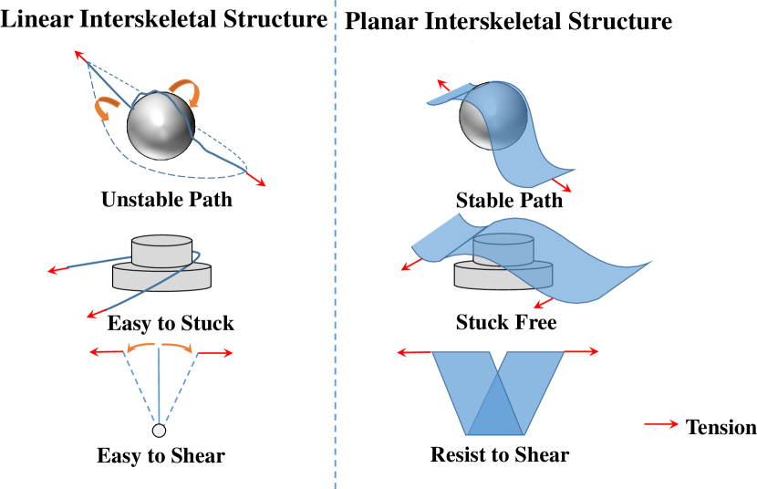
We define two types of interskeletal structures; linear interskeletal structure and planar interskeletal structure. Linear interskeletal structure is attached to skeletal structures with points and linearly contacts with skeletal structures. Planar interskeletal structure is attached to skeletal structures with lines and planarly contacts with skeletal structures. The planar interskeletal structure has the following three merits: (1) it can maintain the stable path; (2) it has stuck-free design; (3) it has high durability to the shear force.
II-A Stable Contact Realized by Planar Structures
When the planar interskeletal structure contacts with the spherical skeletal structure, it can fit the skeletal structure by changing its path to transit to a lower energy potential state. This characteristics of the planar interskeletal structure keeps the skeletal structure inside of its surface. However, the skeletal structure under the linear interskeletal structures can easily deviate from them. When the joint deviates from the linear interskeletal structure, it is hard to support or control the joint by ligaments or muscles [7]. On the other hand, the planar interskeletal structure can stably transmit the muscle tension to the joint because it can maintain the planar contact with the skeletal structure even if the joint angle changes.
II-B Catching Prevention Mechanism by Planar Structure
The linear interskeletal structure has small contact areas and is often caught in roughness of skeletal structures. This phenomenon increases involuntary tension between tendons in linear interskeletal structures, and therefore forcibly causes the change of muscle path and increases friction. Compared to linear interskeletal structures, planar interskeletal structures have large contact surfaces with skeletal structures and cover skeletal structures by their surfaces. This feature prevents the planar interskeletal structure from being caught in the folds of skeletal structures.
II-C Durability to Shear Force
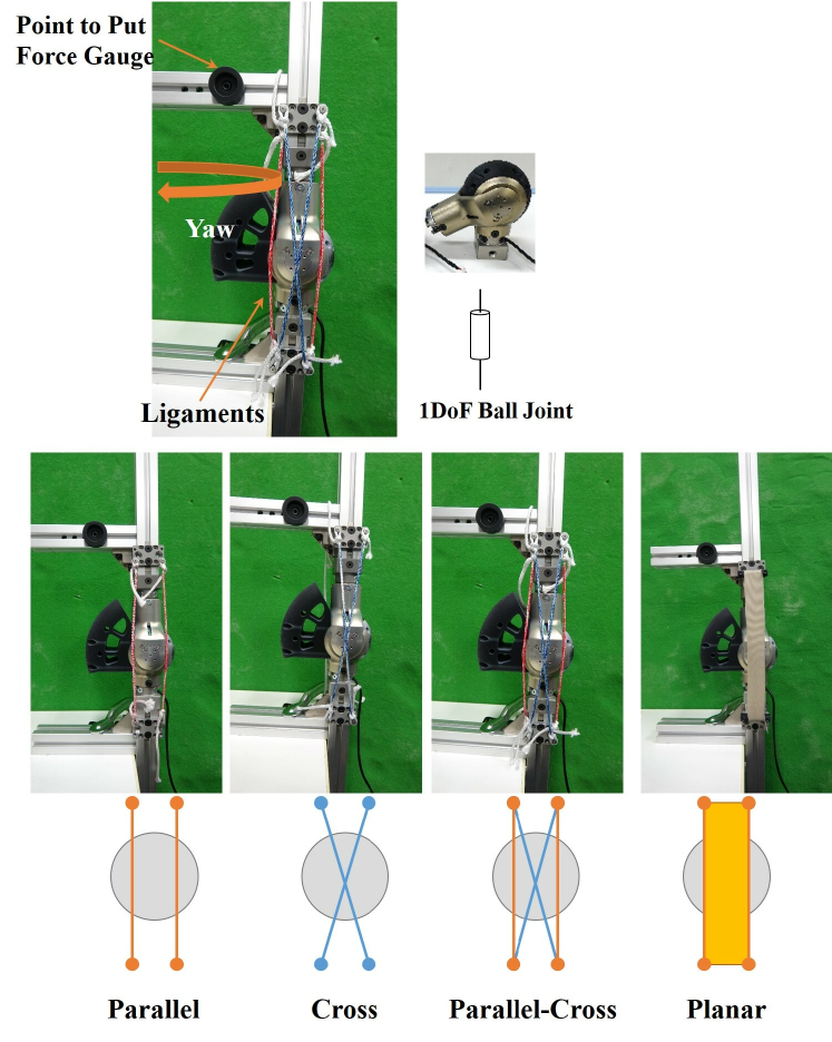
The linear skeletal structure can handle force in the pulling direction by its elasticity on the condition of being fixed by their position (rotationally free), but can hardly handle force in the orthogonal direction. Therefore the planar muscle [7], which is simply constructed by parallel muscles, cannot produce high power in the shear direction. On the other hand, we expect the planar interskeletal structures to handle force in the shear direction by interfering with fibers. We model the elasticity of planar interskeletal structures as a cluster of fibers and compares it with some liner interskeletal structures. Fig. 3 shows schematic diagram of skeletal structures.
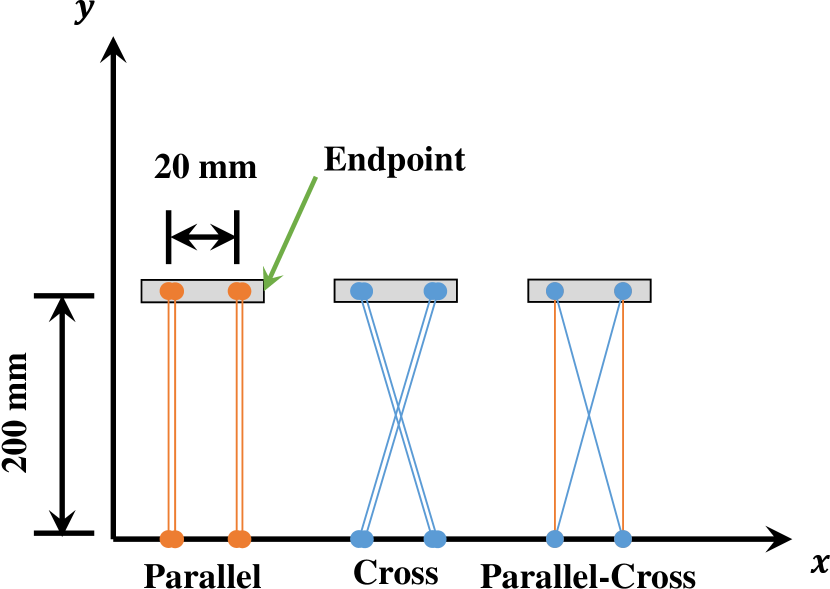
Breen, et al. modeled the precise model of woven cloth based on the minimization of energy [8]. However, in this study, we model woven cloth as truss structure which is tracked by parallel and crossed wires (as shown in parallel-cross in Fig. 3), to consider external forces in only two directions on surface. The model which is tracked by parallel wires (Fig. 3 parallel) and the model which is pulled by crossed wires (Fig. 3 cross) will be compared with the planar-coss model. We assume that the tension and the elongation of wires have the following relationship.
| (1) |
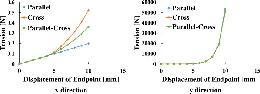
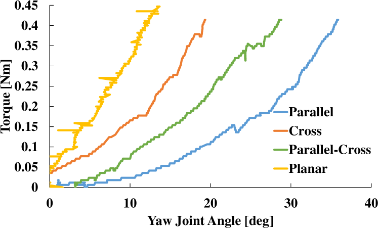
is the tension and is the stiffness of wire. is multiplied by the difference of current length of wire and equilibrium length of the wire . We modeled it so that the tension of the wire develops according to the exponential function as the wire elongates. The tension develops only when the wire elogates over the constant elongation. The dead-band of the each wire is setted in . We set /mm, mm. is calculated based on the assumption that mounting points are 200mm away in the direction of axis in Fig. 3, 20 mm away in axis. On the condition that each structure has 4 wires, the result is shown in Fig. 4. It shows that parallel-cross structure can bear the force of the shear direction more than parallel structure and cross structure. In addition, this result shows that three sutructures have almost same durability in the pulling direction, but parallel-cross structure is a little stronger than cross structure in the pulling direction. Parallel structure is most strongest in the pulling direction. However, in order to use the advantage of merits described in II-A and II-B, planar structure which is modeled as parallel-cross sturucture is necessary, because linear sturcture cannot use the advantage of these merits.
The actual elasticity of each model against shear force was verified in an experiment using wires by Dyneema. An overview of the experiment is shown in 5. In this experiment, the wires were attached in such a way that restoring force was generated for the yaw degree of freedom of the knee joint as described in IV-B. In addition to the three wire attachment settings, a planar structure made of cloth was added for comparison. The results of the experiment are shown in 6. The result shows similar tendency to the simulation result. Although it is not possible to simply compare wires and a cloth because of the different materials and attachment methods, the planar structure made of a cloth is superior to the wire in terms of elasticity.
III DEVELOPMENT OF MUSCULOSKELETAL LEGS WITH PLANAR INTERSKELETAL STRUCTURES
In this section, examples of applying the interskeletal planar structure to a humanoid robot will be described. First, the specification of ”MusashiOLegs” will be described. Next, the requirements for the application of the planar interskeletal structure to musculoskeletal legs will be described. Finally, we will describe the implementation of the planar interskeletal structure to the MusashiOLegs.
III-A Musculoskeletal Humanoid “MusashiOLegs”
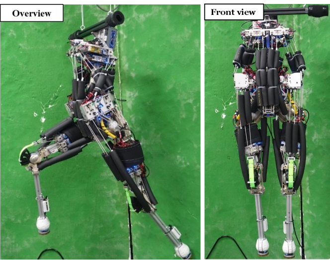
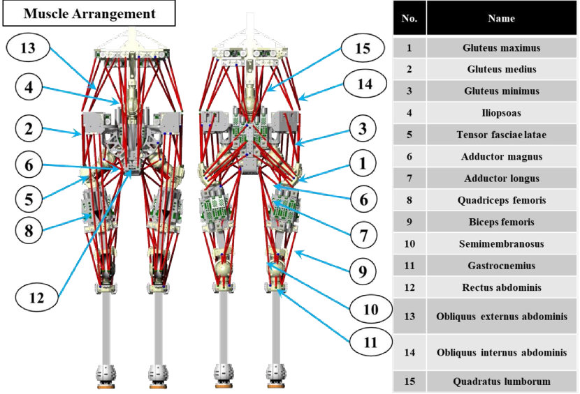
In this research, we developed the musculoskeletal humanoid legs MusashiOLegs (Fig. 7) as a successor of the musculoskeletal humanoid Musashi [9]. MusashiOLegs has 3 DOF in the spine joint, 3 DOF in the hip joints and 2 DOF in the knee joints. Each joint are constructed with pseudo spherical joints [9]. We show the overview and the muscle arrangement of MusashiOLegs in Fig. 7. The skeletal structures are drived by the contraction of the muscles (BLDC motors wind the chemical fiber Dyneema) [10]. It has 40 actuators as muscles, and some wires are folded back to gain enough torque with relatively few actuators.
III-B Design Requirements of Planar Interskeletal Structures
This section discusses the requirements of applying the interskeletal planar structure to humanoid robots. We classify the interskeletal structures into two types; the passive planar interskeletal structure and the active planar interskeletal structure. The passive planar structure cannot produce force by itself and only transmit force to the other body parts like ligaments. The active planar structure exists in actively drivable body parts such as muscles.
III-B1 Passive Planar Interskeletal Structures
Ligaments is an example of interskeletal structures which act passively to joints. The main role of passive planar interskeletal structures is to restrict the range of joint angles and stabilize joint movement. These inskeletal structures cannot produce tension or torque by itself. Therefore it is necessary to attach skeletal structure by human so that it can produce tension only at the angle limit. Next, we clarify the requirements to design a passive planar interskeletal structure as a body part of a musculoskeletal humanoid.
We use non-rigid material to achieve soft angle limit like a human being. Continuously applying tension to non-rigid material lead to irreversible change of its sturcture and weaken the tension generated by its material. To keep constant tension at the angle limit, the tension of elastic material should be adjusted if it is necessary. Makino, et al. developed a mechanism which can restrict DOF in finger joints using linear interskeletal structures (wires) in a five-fingered hand with machined springs [11]. In [11], they have shown twisting wires can adjust the equilibrium length and the tension of the ligament. However, when using the planar interskeletal structure to restrict joints, we cannot twist the planar structures, such as woven cloth. The planar structure should be fixed to skeletal structure with line contact so that the planar structure can be pulled as 2d structure. In addition, to prevent the interference of the interskeletal structure with muscles, the attachment part should be compact.
To summarize these conditions, the requirements are the following.
-
•
Easy to adjust the tension
-
•
Capable of fixing the interskeletal structure to the skeletal structure by line contacts
-
•
Compact structure
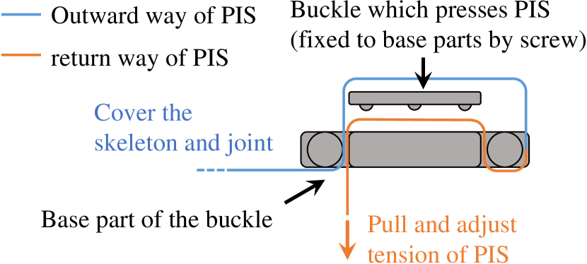
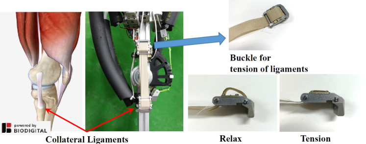
We adapt buckle mechanism (Fig. 8) to satisfy these requirements. This mechanism can strongly hold ligament by pressing force and friction of cover parts and can easily change the length of the ligament. In addition, separating this mechanism into two parts makes this mechanism compact.
III-B2 Active Planar Interskeletal Structures
In comparison to a ligament, the muscle can actively contract. Ligaments are required to perform tension around the angle limit of the joint. Planar muscles are on the contrary required to perform and transmit torque generated from each muscle in any configuration. When planar muscle is actuated, muscles contact strongly with skeletal structures and there can be large friction. Therefore we need to reduce friction between muscles and skeletal structures in order to keep muscles moving. To summarize these conditions, the requirements which can realize the actively drivable planar interskeletal structure are following.
-
•
Structure which can maintain the sufficient moment arm to perform high joint torque
-
•
Surface material which enables smooth contact of muscle with a skeletal structure
The smooth contact of muscles with skeletal structure is considered to be especially important. In the human body, a sheath of tendon and a fascia plays this role.
III-C Application of Planar Interskeletal Structures to Musculoskeletal Legs ”MusashiOLegs”
In this subsection, we discuss the application of planar interskeletal sturcture to the musculoskeletal humanoid. First, we describe the two passive planar interskeletal structures; iliofemoral ligaments and knee collateral ligaments. Next, two active planar interskeletal structures is described; pattella ligaments and gluteus maximus.
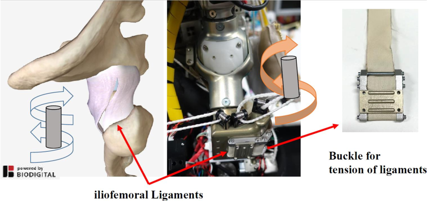
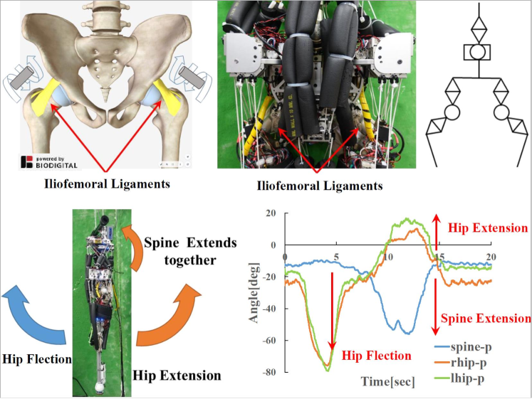
III-C1 Iliofemoral Ligaments
The iliofemoral ligament is the ligament that winds around a caput femoris. The main role of this ligament is to restrict the hip joint angles. The iliofemoral ligament relieves when the hip joints are bent. On the other hand, when the iliofemoral ligament is tensioned, it prevents the trunk of the body from dropping backward. An iliofemoral ligament should be attached to the bending axis of hip joints winding around them as a human being. This mechanism is expected to work as a soft joint limit in the hip joints. We used the buckle mechanism (Fig. 8) to attach ligament through the underside of the bending axis of hip joints (Fig. 9). This planar interskeletal structure uses the advantage of all merits described in section II to wind around the hip joint and softly limit the range of joint angle.
III-C2 Knee collateral ligaments
The collateral ligament in the knee joint softly restricts the movement of the knee joint in the bending position and stabilizes the knee joint in the extending position. We used the buckle mechanism to attach the collateral ligament to the skeletal structure. They were attached over the knee joint in the same positions as those in the human knee joint. The tension of the collateral ligament is adjusted in a soft bending position (Fig. 10). This planar interskeletal structure uses the advantage of all merits described in section II to stably contact with skeletal sturctures and softly limit joint angles.
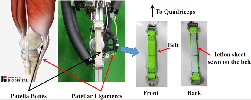
III-C3 Patella ligaments
The patella ligament connects a quadriceps femoris with a tibia. This ligament is not a muscle. However, in this study, we treat it as the actively drivable interskeletal structure, because its role is close to a muscle.
The patella ligament expands and contracts along the front side of the femur and patella bone. If there is no patella bone, the moment arm in the knee joint will decrease by [13]. Therefore to maintain the moment arm of the patella ligament and the quadriceps, the musculoskeletal humanoid needs the skeletal structure biologically equivalent to the patella bone. We used the skeletal component equivalent to the patella bone to maintain the moment arm.
To achieve smooth contact of the patella ligament with the patella bone, we used the belt attached to the muscles through the relay parts that fold back muscles. Besides, we sewed the Teflon sheet on the backside side of the belt, as shown in Fig. 11. This mechanism makes the patella ligament strong and decreases the friction between the patella ligament and the patella bone. This is one of the merits of planar interskeletal structure described in II-B. This planar interskeletal structure also uses the advantage of merits described in II-A to stably transmit torque from muscle actuator to skeletal sturcture.
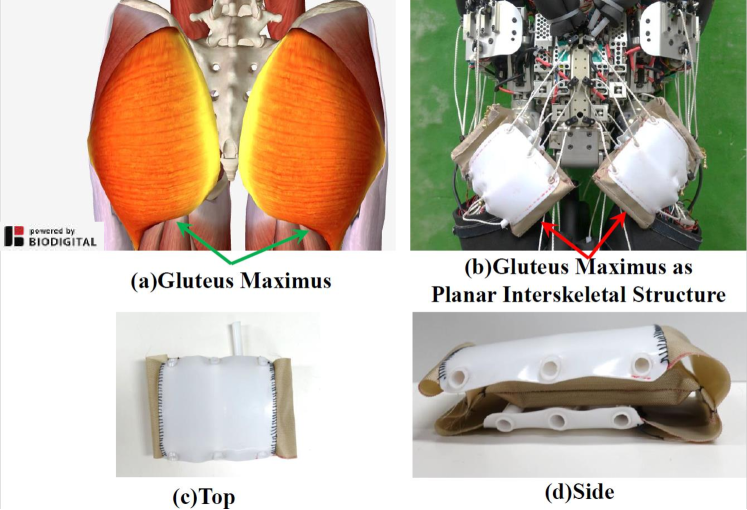
III-C4 Gluteus maximus
The gluteus maximus is the strongest muscle in the human body and is the crucial antigravity muscle [3]. This muscle covers the hip joint, and the main role is extension and extorsion of the hip joint. Not only the surface contact by the planar interskeletal structure but also the thickness of the gluteus maximus is considered to play an essential role in maintaining the moment arm. In addition, we had to decrease the friction between the gluteus maximus and the hip joint to actuate the hip joint, because the gluteus maximus has a huge contact area with a skeletal structure and performs high torque sufficient to support the whole weight of the human body.
In this study, we realized the thick gluteus maximus by using the pocket which contains polyethylene cushioning material sewn to the Teflon sheet, as shown in Fig. 12. To prevent friction between wires and skeletal structure, we implemented the Teflon tube to protect the wire path. Also, we achieved smooth contact of planar interskeletal structure and the hip joint by using the Teflon sheet sewn to the outside of the polyethylene pocket. This planar interskeletal structure uses advantage of the merit described in II-A and II-B.
IV Experiments
IV-A Basic Experiment of Planar Iliofemoral Ligament
First, we will confirm that the iliofemoral ligament made of the elastic planar interskeletal structure can softly restrict the range of motion. In the human body, when a human moves the femur towards the backside of the body, tension is applied to the iliofemoral ligament and the iliofemoral ligament restricts the extension axis of the hip joint. This restriction makes the pelvis and the femur move together. We confirm that the hip joint of MusashiOlegs has the same function.
The external force is applied to the femur in both directions of extension and bending, on the condition of the trunk of the body being suspended. In order to evaluate the passive torque in the hip joint applied by the ligament, muscles around the pelvis are slackened. The result of this experiment is shown in Fig. 13. In Fig. 13, spine-p, rhip-p, lhip-p represent the joint angle of the spine pitch, rleg hip pitch and lleg hip pitch. When the hip joint is bent, the joint angle of the spine does not change. However, when the hip joint is extended, the passive torque by the iliofemoral ligament locks the hip joint and the joint angle of the spine changed.
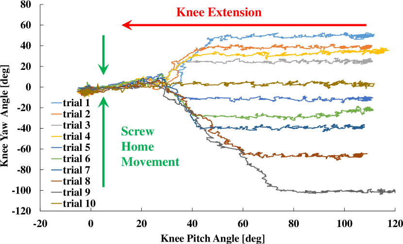
IV-B Human Comparable Moving Function: Screw-Home Movement of Knee Joint
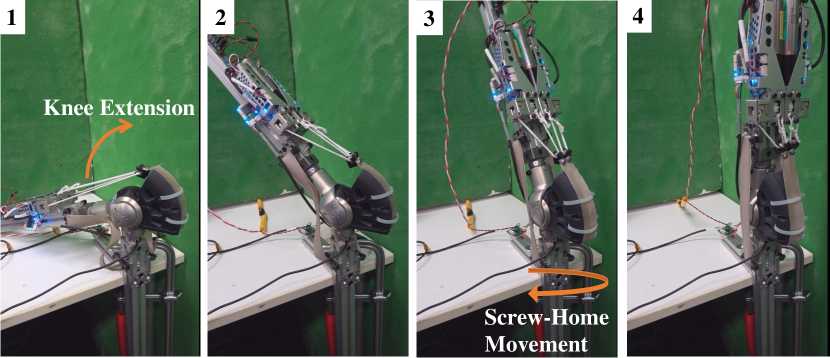
In this experiment, we confirm that the screw-home movement in the knee joint is realized by the passive torque generated from the planar collateral ligament. The screw-home movement is the function of the planar collateral ligament. The ligament allows complex rotational movement in knee flexion configuration, but the ligament locks the range of angle and stabilizes the knee joint in knee extension configuration. The previous research realized screw-home movement by the only rigid mechanism [14]. However, this mechanism cannot handle the impact force in the knee extension configuration and can break irreversibly. Not only the realization of a complex range of motion but also the soft restriction which can absorb impact force is important. We will show that the planar interskeletal structure implemented in III-C2 can satisfy these characteristics.
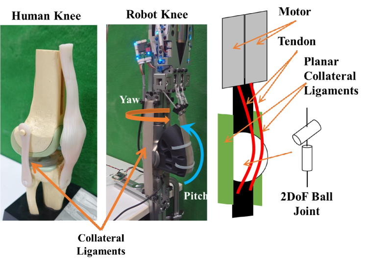
The schematic diagram of the knee joint attached to the collateral ligament and muscles is shown in Fig. 14. The collateral ligament is attached to the skeletal structure over the pseudo spherical joint which has 2Dof in yaw and pitch axis in Fig. 14. The quadriceps extend the knee joint. The collateral ligament should be attached to the skeletal structure of the thigh, because the screw-home movement is also the effect of the quadriceps. In this study, to evaluate only the effect of passive torque by the collateral ligament, the knee joint was fixed so that the quadriceps do not generate screw torque.
In these conditions, we set the knee joint bent and screwed randomly and extend knee joint using muscle actuators. Fig. 15 shows the result of 10 trials of extension of the knee joint from the randomly screwed configuration. This figure shows that the yaw joint angle of the knee joint converged to deg as the knee extends. As shown in Fig. 16, when the screwed knee joint extends, we observe that the screw-home movement by the passive torque of the collateral ligament locked the rotational axis of the knee joint as the knee joint extends.
IV-C Performance of High Torque in a Wide Range of Motion
We conducted a squat motion experiment to show that the musculoskeletal humanoid legs with planar interskeletal structures can perform high torque in a wide range of motion. In this experiment, muscles must maintain a moment arm to support the body weight of humanoid legs in a wide range of motion. We send muscle length direction to each muscle actuators using learned body image [15] which maps muscle length to joint angles.
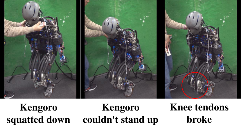
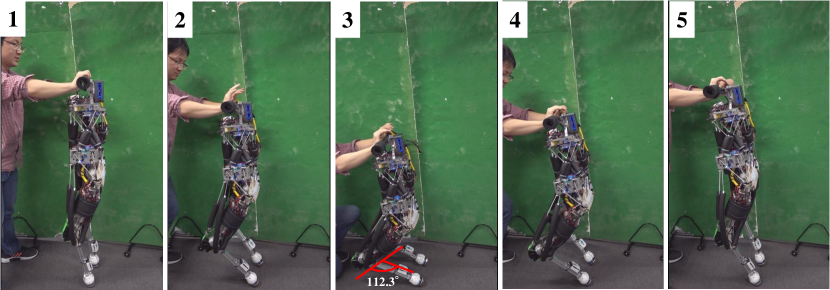
We show the result of the experiment in Fig. 17 and Fig. 18. The musculoskeletal humanoid without the planar interskeletal structures [16] could not perform the squat motion, because it could not apply sufficient torque to joints. On the other hand, the musculoskeletal legs with the planar interskeletal structures achieved deep squat motion from the state {} .
IV-D Pedal Switching Experiment as Environmental Contact Situation
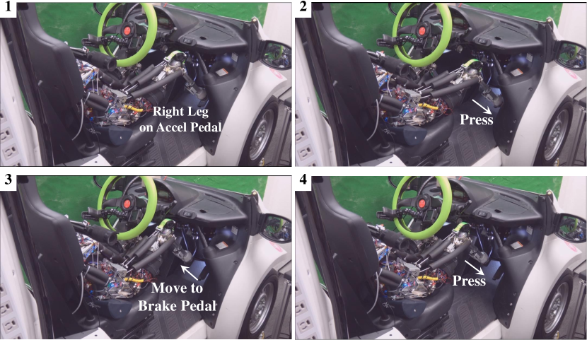
Finally, we conducted the pedal switching experiment as environmental contact situation. In the pedal switching experiment, muscles must maintain the moment arm to transmit sufficient torque to each joint in tight postures. Also, the musculoskeletal legs must perform the task under friction with the car seat. In this experiment, the musculoskeletal legs is required to, first press the accel pedal, second put its foot away from the accel pedal, third move its foot to the above position of the brake pedal and finally press the brake pedal. The car used in this experiment is B.COM Delivery of extremely small EV COMS series. We send muscle-length direction to each muscle actuator using learned body image [15] which maps muscle length to joint angles.
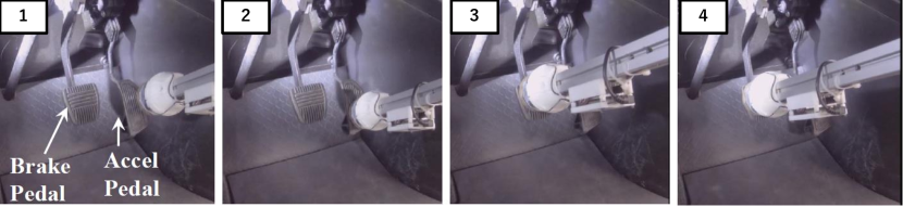
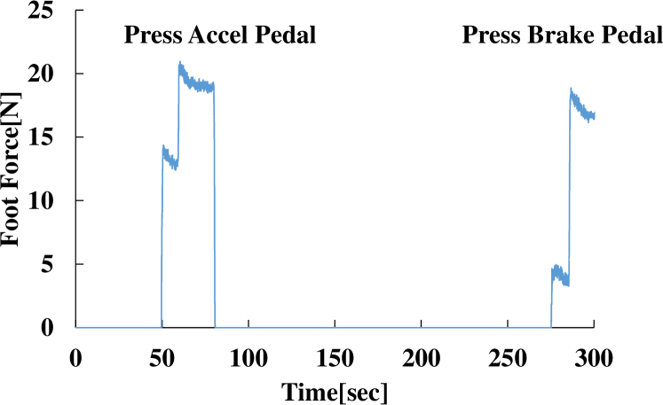
The experimental appearance is shown in Fig. 19. In addition, Fig. 20 shows the appearance from the view above feet and Fig. 21 shows the foot force sensor data during the experiment. In previous research, the musculoskeletal humanoid pressed pedals using one leg for each pedal; the left leg for the brake pedal, and the right leg for the accel pedal [17]. This was because that the musculoskeletal humanoids could not produce enough torque to raise each leg in a seated situation. On the other hand, the musculoskeletal humanoid legs with planar interskeletal structures achieves pedal switching by single-leg like a human being. It can produce enough torque to raise the leg in the seated situation desptie friction between the car seat and the body.
V CONCLUSION
In this study, we discussed the role of interskeletal structures that cover joints and tract different skeletal structures and showed the importance of planar interskeletal structures. We showed that the planar interskeletal structure has three key features; stable contact with the surface of the skeletal structure, prevention of being caught in folds of structure and the tolerance of the tension in the shear direction. About the tolerance of the tension in the shear direction, we showed planar structure has better resistance compared to liner structures, using simulation. Then we designed the musculoskeletal legs with planar interskeletal structures. We applied passive planar interskeletal structures to iliofemoral ligaments and knee collateral ligaments in order to softly restrict joint angles in the angle limit. Active planar interskeletal structures were applied to patella ligaments and gluteus maximus in order to maintain the moment arm of muscle and stably transmit torque to skeletal structures. Also, we conducted experiments that require human comparable moving function and verified the effectiveness of the planar interskeletal structures. In future works, we would like to investigate control systems utilizing the high joint stiffness and stable torque performance. Also, we would like to realize the learning based controller which can control the behavior of planar interskeletal structures.
References
- [1] Y. Asano, K. Okada, and M. Inaba, “Design principles of a human mimetic humanoid: Humanoid platform to study human intelligence and internal body system,” Science Robotics, vol. 2, no. 13, 2017.
- [2] I. Mizuuchi, T. Yoshikai, Y. Sodeyama, Y. Nakanishi, A. Miyadera, T. Yamamoto, T. Niemela, M. Hayashi, J. Urata, Y. Namiki, T. Nishino, and M. Inaba, “Development of musculoskeletal humanoid kotaro,” in Proceedings 2006 IEEE International Conference on Robotics and Automation, 2006. ICRA 2006., 2006, pp. 82–87.
- [3] I.A.Kapandji, PHYSIOLOGIE ARTICULAIRE ii. Lower Limb 5th ed. Ishiyaku Pub, inc, 1996.
- [4] A. Fujii, S. Nakashima, M. Kawamura, K. Kawaharazuka, S. Makino, Y. Asano, K. Okada, and M. Inaba, “Development and functional evaluation of a deformable membrane capsule for an open ball glenohumeral joint,” in 2018 7th IEEE International Conference on Biomedical Robotics and Biomechatronics (Biorob), 2018, pp. 853–858.
- [5] T. Sonoda, “Design of rolling joint employing ligament-type constraint method (in japanese),” Journal of the Robotics Society of Japan, vol. 37, no. 10, pp. 955–961, 2019.
- [6] Z. Xu, E. Todorov, B. Dellon, and Y. Matsuoka, “Design and analysis of an artificial finger joint for anthropomorphic robotic hands,” in 2011 IEEE International Conference on Robotics and Automation, 2011, pp. 5096–5102.
- [7] M. Osada, T. Izawa, J. Urata, Y. Nakanishi, K. Okada, and M. Inaba, “Approach of “planar muscle” suitable for musculoskeletal humanoids, especially for their body trunk with spine having multiple vertebral,” in 2011 11th IEEE-RAS International Conference on Humanoid Robots, 2011, pp. 358–363.
- [8] D. E. Breen, D. H. House, and M. J. Wozny, “Predicting the drape of woven cloth using interacting particles,” in Proceedings of the 21st Annual Conference on Computer Graphics and Interactive Techniques, ser. SIGGRAPH ’94. New York, NY, USA: ACM, 1994, pp. 365–372.
- [9] K. Kawaharazuka, S. Makino, K. Tsuzuki, M. Onitsuka, Y. Nagamatsu, K. Shinjo, T. Makabe, Y. Asano, K. Okada, K. Kawasaki, and M. Inaba, “Component modularized design of musculoskeletal humanoid platform musashi to investigate learning control systems,” in Proceedings of the 2019 IEEE/RSJ International Conference on Intelligent Robots and Systems, 2019, pp. 7300–7307.
- [10] Y. Asano, T. Kozuki, S. Ookubo, K. Kawasaki, T. Shirai, K. Kimura, K. Okada, and M. Inaba, “A sensor-driver integrated muscle module with high-tension measurability and flexibility for tendon-driven robots,” in 2015 IEEE/RSJ International Conference on Intelligent Robots and Systems (IROS), 2015, pp. 5960–5965.
- [11] S. Makino, K. Kawaharazuka, A. Fujii, M. Kawamura, T. Makabe, M. Onitsuka, Y. Asano, K. Okada, K. Kawasaki, and M. Inaba, “Five-fingered hand with wide range of thumb using combination of machined springs and variable stiffness joints,” in 2018 IEEE/RSJ International Conference on Intelligent Robots and Systems (IROS), 2018, pp. 4562–4567.
- [12] “Biodigital human: Anatomy and health conditions in interactive 3d,” https://www.biodigital.com/.
- [13] K. Hervert, “Mechanical function of the patella,” The Journal of Bone and Joint Surgery, vol. 53A, pp. 1551–1560, 1971.
- [14] Y. Asano, H. Mizoguchi, T. Kozuki, Y. Motegi, J. Urata, Y. Nakanishi, K. Okada, and M. Inaba, “Achievement of twist squat by musculoskeletal humanoid with screw-home mechanism,” in 2013 IEEE/RSJ International Conference on Intelligent Robots and Systems, 2013, pp. 4649–4654.
- [15] K. Kawaharazuka, S. Makino, M. Kawamura, A. Fujii, Y. Asano, K. Okada, and M. Inaba, “Online self-body image acquisition considering changes in muscle routes caused by softness of body tissue for tendon-driven musculoskeletal humanoids,” in Proceedings of the 2018 IEEE/RSJ International Conference on Intelligent Robots and Systems, october 2018, pp. 1711–1717.
- [16] Y. Asano, T. Kozuki, S. Okubo, M. Kawamura, S. Nakashima, T. Katayama, I. Yanokura, T. Hirose, K. Kawaharazuka, S. Makino, Y. Kakiuchi, K. Okada, and M. Inaba, “Human mimetic musculoskeletal humanoid kengoro toward real world physically interactive actions,” in 2016 11th IEEE-RAS International Conference on Humanoid Robots, 2016, pp. 876–883.
- [17] K. Kawaharazuka, K. Tsuzuki, S. Makino, M. Onitsuka, K. Shinjo, Y. Asano, K. Okada, K. Kawasaki, and M. Inaba, “Task-specific self-body controller acquisition by musculoskeletal humanoids: Application to pedal control in autonomous driving,” in Proceedings of the 2019 IEEE/RSJ International Conference on Intelligent Robots and Systems, 2019, pp. 813–818.