Deriving Rewards for Reinforcement Learning from Symbolic Behaviour Descriptions of Bipedal Walking
Abstract
Generating physical movement behaviours from their symbolic description is a long-standing challenge in artificial intelligence (AI) and robotics, requiring insights into numerical optimization methods as well as into formalizations from symbolic AI and reasoning. In this paper, a novel approach to finding a reward function from a symbolic description is proposed. The intended system behaviour is modelled as a hybrid automaton, which reduces the system state space to allow more efficient reinforcement learning. The approach is applied to bipedal walking, by modelling the walking robot as a hybrid automaton over state space orthants, and used with the compass walker to derive a reward that incentivizes following the hybrid automaton cycle. As a result, training times of reinforcement learning controllers are reduced while final walking speed is increased. The approach can serve as a blueprint how to generate reward functions from symbolic AI and reasoning.
I Introduction
Many problems, in particular in robotics, can be phrased as optimization problems. Popular approaches to solve optimization problems are unsupervised learning techniques, such as reinforcement learning (RL) [1, 2]. RL requires both the definition of a reward function, which characterizes the quality of a solution, and an optimization algorithm to reach the maximum reward. When solving a specific problem arguably most of the time is spent on the former: the definition of a reward function that captures the essence of the desired solution, is actually maximized by the desired solution, and allows the algorithm to follow a gradient towards the desired solution. Poorly designed reward functions can lead to the algorithm getting stuck in local minima, very slow initial learning if gradients of the reward are shallow, or solutions that yield high rewards, but that do not resemble the intended target behaviour. While reward functions that yield good results for specific behaviours are discovered over time, there is no principled way of translating a symbolic description as a human would give it to a numerical reward function that leads to this behaviour if maximized. The contribution of this paper is a principled way to derive such reward functions from symbolic descriptions. We tackle the problem of bipedal walking behaviour, but the general approach can be applied to many other problems.
Walking is a highly relevant locomotion mode in robotics. Whereas there are many proven combinations of reward formulations and RL algorithms in the literature for bipedal [3, 4, 5, 6, 7] and quadrupedal [8, 4, 9, 10] robots, both in simulation and directly on real world robots [8, 11], the reward terms are mostly heuristically generated, and there is no consensus about which reward terms are necessary or sufficient. Finding a principled way to infer a reward function with minimal heuristics is the topic of inverse reinforcement learning (IRL). More precisely, IRL tries to solve the problem of inferring the reward function of an agent, given its policy or observed behaviour (see [12] for a survey). This may be complicated, as it requires a very precise understanding of the solution space; the reward function not only has to characterize the optimal solutions, it also has to guide the heuristic towards it without creating too many local minima on the way, as mentioned before. This precise understanding can be difficult to infer from observations of desired behaviour.
In contrast, humans are able to learn new behaviours from informal verbal or symbolic descriptions, also without observing demonstrations or teachers as used in IRL. Such approaches have not yet been well-studied for generating physical movements in underactuated robots. Thus, in this paper, we try to use symbolic descriptions of behaviour, as a teacher or coach could give, to derive a specific reward term for walking. For this, we use descriptions of the human gait as a succession of certain phases, such as “stance foot is in front of swing foot” or “swing leg is moving forward”. At first glance, it is not straightforward to put these notions into formulas. However, these formal descriptions specify the humanoid’s configuration in certain orthants of its phase space. This observation leads us to a formal characterization of the human gait given by a succession of phase space orthants. In the context of RL, we show that this characteristic can be exploited to effectively reduce the size of the search space when incorporated in the reward function. Using the compass gait as an example, we show that our method indeed improves learning times and walking speed. The simplicity of our technique should make it applicable to other walking robots or similar situations where a good reward function is hard to come by.
Organization
Section II presents the formalization of the compass walker gait as a hybrid automaton over state space orthants. Section III uses this symbolic formalization to derive a reward function term. Experimental results are presented in Section IV. Section V draws the conclusion and discusses future research directions.
II Symbolic Formalization
II-A From Informal to Formal Descriptions
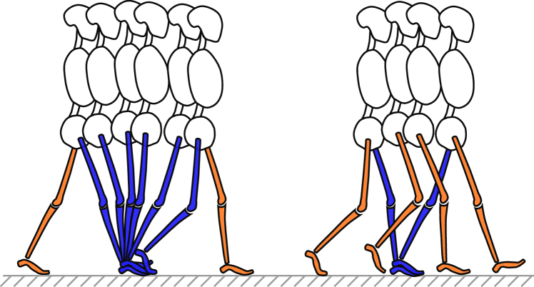
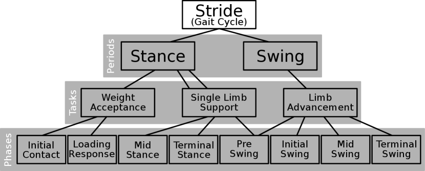
Human walking behaviour is not easy to formalize mathematically. It consists of various phases serving a different purpose each, which are combined to an overall walking behaviour. It becomes even more complicated when considering legged locomotion variations such as running or hopping. For example, Perry [13] decomposes the stride (gait cycle) into different phases, grouped by tasks according to their function (Figure 1); different tasks accomplish weight acceptance, limb support and limb advancement (i.e. the weight is supported by one limb while the other swings forward; see Figure 2). The individual phases are described informally: “The swing foot lifts until the body weight is aligned over the forefoot of the stance leg”, or “The second phase begins as the swinging limb is opposite of the stance limb. The phase ends when the swinging limb is forward and the tibia is vertical, i.e. hip and knee flexion postures are equal” ([13] pp. 9–16).
The aspect to emphasize here is that phases and especially transitions between two phases are characterized by relations of body parts, some specific joint angle, or sign changes of angular velocities. Thus, carefully defining the angles that describe a bipedal system allows us to associate each phase with a hypercube within the system’s phase space. Therefore, we can give a formal characteristic of a human gait sequence by a set of hypercubes in state space and a rule in which order to traverse them. The nature of the description lends itself to a formalization in terms of hybrid automata.
In the following we apply these concepts to the compass gait model, as a simple and well studied system to test our approach. Despite its simplicity, it can exhibit a passive walking behaviour on a slope actuated by gravity [14, 15]. We consider an actuated version on flat ground, where a virtual gravity controller can be used to generate the same gait pattern [16, 17]. We first recall the system dynamics.
II-B Dynamics of the Compass Walker
The compass walker [14, 15] is a simple bipedal walker. Its two legs are called the stance leg, which connects with the ground and supports the weight, and the swing leg, which moves freely from the hip joint. It behaves like a double pendulum with a pin joint at the foot of the stance leg. Consequently, its dynamics are described as follows:
| (1) |
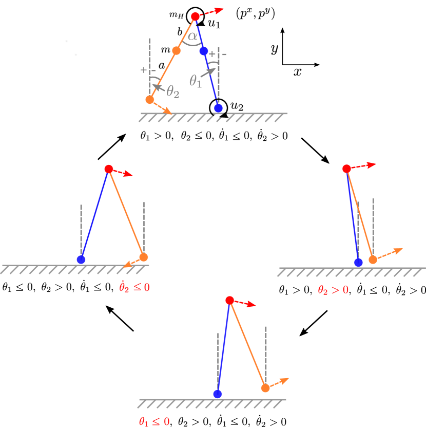
with being the configuration vector, where is the angle of the stance leg to the upright, and is the angle between the swing leg and the upright, the torque vector, with the torque at the hip and the torque at the ankle, and the coordinates of the hip joint (cf. Figure 3).
Gravity acts according to
| (2) |
where is the mass of leg, given as single mass point at from the foot, is the length of the leg, and is the mass point at the hip (cf. Figure 3). Control acts on the system via
| (3) |
Inertial and Coriolis matrices are described by
| (4) | ||||
| (5) |
Ground collision of the swing leg occurs when it is in front of the stance leg, the task space velocity of the swing leg is negative in , and .111 Notice that during the forward swing, the swing leg will penetrate or touch the ground due to the simplified model assumptions (i.e. no knee joint is included); we disregard this in our simulation. When ground contact occurs, swing and stance leg immediately change roles and the angular momentum is transferred assuming a perfectly inelastic collision. This means gets assigned to and vice versa, and the transition of angular velocities is calculated via
| (6) | |||||
| (7) |
where +/- denote states right after/before collision and is the inter-leg angle at the moment of transition. The transition matrices are given by
where . This formulation largely follows [16, 17], further mathematical details can be found in [14].
II-C A Formal Model of Ideal Walking
Now, the link has to be made to relate the states of these dynamics with the walking phase descriptions mentioned above. The crucial observation is that the different phases are determined by whether the swing leg is to the left or to the right of the stance leg, whether the stance leg is leaning left or right and whether the legs are moving clockwise or counter-clockwise around their respective joints. This can be described in terms of , and the corresponding angular velocities and , which spans the phase space of the compass walker. Figure 3 shows this decomposition, where the swing leg starts from its hindmost position and swings all the way to the front, when it becomes the stance leg. The case distinction of being smaller or larger than zero yields sixteen partitions (orthants) of the state space, and the observation above defines a cycle involving only four of these. In the following section, we give a formal model of this ideal walking behaviour. We then use this model to construct a reward function which encourages the compass walker to adhere to this formal model; in other words, we reward walking “properly”.
The formal model of ideal walking behaviour consists of a cycle of the four orthants sufficient for stable walking. It is based on hybrid automata, as introduced by Alur [18] and Henzinger [19]. Hybrid automata allow combining continuous behaviour with discrete states. Briefly, a hybrid automaton is given as a tuple
| (8) |
where is a set of real-valued data variables valued in , is a set of locations (discrete states), and is a transition relation between the states. Further, for each , is a set of activities specified by differential equations, is an invariant predicate, and for each , is a transition relation between data variables. Intuitively, the automaton starts in a state with data variables set to s.t. is true. The continuous behaviour of the data variables is specified by . As soon as the predicate becomes false, the automaton transitions into a state where ; the values of the data variables may then change into such that is true.222Note that although our model is deterministic, in general hybrid automata can be non-deterministic.
Here, the state variables are given by , and we have four locations, corresponding to the states in Figure 3:
| (9) | ||||
| (10) |
The activities for are given by the differential equations (1) to (5). The invariants specify the orthants in the system state as follows:
| (11) | ||||
| (12) | ||||
| (13) | ||||
| (14) |
The transition relation specifies the cycle mentioned above, and corresponds to the arrows between the four states in Figure 3:
| (15) |
When a transition occurs, specifies the possible values of . This mapping is the identity, except at the last transition , where and are interchanged, and the impulse is transferred between and :
| (16) |
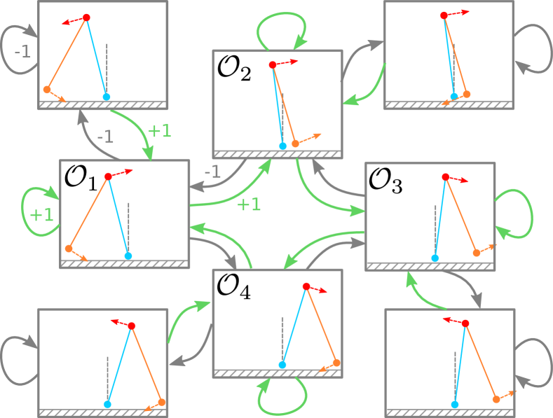
where is calculated according to the impulse transition equation (7). The automaton defined by equations (9) to (16) can also be described by a diagram (cf. Figure 4). The diagram shows the states, the state invariants defined by , the state transitions in , and the change of the state variables after the transitions defined by ; it does not show the identities in (16), i.e. , etc. in all other transitions, as this is usually elided, and for clarity we also do not show the activities (defined by ) in the diagram.
III Reward Formulation
For an agent to make use of this exploration space reduction given by the hybrid automaton formulation, we define the orthant reward term as:
| (17) |
Here, refer to the definitions of the hybrid automaton of ideal walking from Section II-C, and maps the state to the current orthant , . This reward is visualized in Figure 5; essentially, it incentivizes the walker to follow the sequence of the formal model developed in Section II-C.
As comparison, we also consider a reward which is commonly used in locomotion tasks, namely rewarding task space motion in the intended direction. This reward reads
| (18) |
where denotes the Heaviside function, and the task space coordinates of the hip joint (see Figure 3). Further, rewards are used to encourage smooth controls (), high walking distance (), and punish falling (). These terms are defined as:
| (19) | ||||
| (20) | ||||
| (21) |
The full reward is then given as
| (22) | ||||
IV Results and Discussion
Using the previously mentioned formulation, we compared training setups of reward configurations in terms of reward optimization and highest achieved walking distance.333Accompanying code is publicly available at https://github.com/dfki-ric-underactuated-lab/orthant_rewards_biped_rl. The observation in the RL setup was the robot configuration . Thus, a policy was trained mapping the configuration state to the control input. As training algorithm, PPO was chosen [20] in the stable-baselines3 implementation [21] with default parameters. We evaluate different combinations of reward terms to disentangle the effects of the various terms. The different reward setups are detailed in Table I.
| sparse | for | or | for + or | |
|---|---|---|---|---|
| 0.0 | 0.01 | 0.0 | 0.005 | |
| 0.0 | 0.0 | 0.01 | 0.005 |
The other weights in equation (22) were set to . A training episode was terminated if a fall occurred, i.e. if , or the maximal episode length of s was reached. Each training condition was run 15 times with different random seeds and 500000 environment steps per run.
As a baseline comparison, we use the virtual gravity controller
| (23) |
described in [17], simulating passive walking on a slope of rad. The parameters of the compass walker plant used in all simulations is given in Table II, and the initial condition for all experiments was .
| 1 kg | 0.5 kg | 0.5 m | 0.5 m | 1.0 m |
Figure 6 shows the averaged learning curves for the different reward setups, normalized to the reward gained by the virtual gravity baseline controller. Whereas reward setups using forward or orthant reward terms reach close to optimal reward values earlier in training, after around 200000 steps, convergence is slower for the sparse setup. Figure 7 compares the highest achieved walking distance for each reward setup, taken over the 15 runs per setup.444See accompanying video at https://youtu.be/CkvLvz_tLtc. Here, the combined reward of orthant reward and forward velocity reward leads to the fastest convergence and highest achieved walking distance. Similar walking distances are reached after considerably longer time in both individual reward setups of only orthant reward and only forward velocity reward. Strikingly, walking distances for the sparse setup also converge, but at markedly lower values. The standard deviation of the highest achieved reward highest achieved walking distance are shown in Table III.
| setup | sparse | forward | orthant | fwd+ orthant |
|---|---|---|---|---|
| reward | ||||
| walking distance | 1.302 | 1.192 | 0.744 | 1.173 |
In summary, whereas a sparse reward setup reaches comparable performance to the baseline virtual gravity controller, both the typically used forward velocity reward and the novel orthant reward improve the performance, with the combination of both reaching the highest performance. The orthant reward leads to the lowest standard deviation of the performance across trials, making it the most reproducible method in our study. The combination of the orthant and forward reward has an increased standard deviation, however below the values for the sparse reward. Interestingly, both forward and orthant rewards seem redundant: Observing a stable compass gait, both the predicates of ’forward hip velocity is positive’ and ’orthant sequence follows the stable orthant gait cycle’ are always true. Yet the combination of both incentives through the reward function is more successful in reaching higher walking distances than each incentive on its own, at the cost of a slightly reduced reproducibility indicated by the increased standard deviation. This is part of a long-standing question in reward shaping, where the optimal combination of reward terms to achieve a goal is unclear. Too many redundant terms can deteriorate learning, whereas too little guidance can lead to impractical training times or no convergence at all. In comparison to typically used reward terms, the orthant reward is simple and straight forward since it amounts to a single truth value telling the agent whether it is close to the set of desired phase space trajectories.
V Conclusion and Outlook
This paper has presented a first attempt towards creating a link between symbolic reward formulation based on informal descriptions of behaviour and behaviour policy generation. The main novelty of our approach is a systematic way to derive a reward function from an informal description of the desired behaviour in three steps employing well-understood mathematical techniques: (i) from an informal description of the behaviour, we have derived a formal specification of the desired behaviour as a hybrid automaton; (ii) the hybrid automaton is an abstraction of the state space of the system, i.e. a restriction of its phase space; (iii) this restriction allowed to formulate a better reward function for reinforcement learning. We have demonstrated that this kind of input is useful in speeding up the learning process of achieving stable bipedal locomotion; the key here is the effective search space reduction given by the formal model.
It is worth pointing out that although we derive an effective reward function, the main contribution of this paper is the way in which the combination of symbolic description and reinforcement learning improves the overall result; this should work with other reinforcement learning techniques and reward functions as well, but to what degree remains to be investigated. It further remains an open problem to figure out what is the right granularity to seek in reward shaping. For example, it is interesting to study if splitting the orthants into smaller hypercubes and coming up with more fine-grained rules will bring additional improvements in the learning process. Furthermore, this formalization naturally lends itself to applications in curriculum learning, where a coarse grained initial formulation can be made more detailed when the agent reaches a certain proficiency, which could potentially even more effectively guide the learning agent.
This kind of symbolic reward definition maybe be combined with existing inverse reinforcement learning techniques to automatically derive reward specifications for any given behaviour. For example, there is no principal reason why this technique should not work for walking robots with higher degrees of freedom, except that for these the formal model as a hybrid automaton may be not as straightforward to formulate as for the compass walker. In future work, we want to investigate how the present method can be applied to more complex humanoid walking robots (such as [22]) using the basics developed here combined with mapping template models to whole body control.
Another aspect worth exploring is proving properties (such as safety properties) about the controlled system. Here, the formalization as a hybrid automaton has the advantage that powerful tool support exists [23, 24]. This can be used to show that learned behaviours satisfy given properties [25], so our approach can also be used for safety verification of learned robot behaviours. This would be an enormous advantage over existing approaches, where a safety guarantee for learned behaviours cannot be given.
References
- [1] R. S. Sutton and A. G. Barto, Reinforcement learning: An introduction. MIT press, 2018.
- [2] D. Bertsekas, Reinforcement learning and optimal control. Athena Scientific, 2019.
- [3] J. Siekmann, Y. Godse, A. Fern, and J. Hurst, “Sim-to-real learning of all common bipedal gaits via periodic reward composition,” in 2021 IEEE International Conference on Robotics and Automation (ICRA), 2021, pp. 7309–7315.
- [4] N. Rudin, D. Hoeller, P. Reist, and M. Hutter, “Learning to walk in minutes using massively parallel deep reinforcement learning,” in Conference on Robot Learning. PMLR, 2022, pp. 91–100.
- [5] Z. Li, X. Cheng, X. B. Peng, P. Abbeel, S. Levine, G. Berseth, and K. Sreenath, “Reinforcement learning for robust parameterized locomotion control of bipedal robots,” in 2021 IEEE International Conference on Robotics and Automation (ICRA). IEEE, 2021, pp. 2811–2817.
- [6] W. Yu, G. Turk, and C. K. Liu, “Learning symmetric and low-energy locomotion,” ACM Transactions on Graphics (TOG), vol. 37, no. 4, pp. 1–12, 2018.
- [7] K. Green, Y. Godse, J. Dao, R. L. Hatton, A. Fern, and J. Hurst, “Learning spring mass locomotion: Guiding policies with a reduced-order model,” IEEE Robotics and Automation Letters, vol. 6, no. 2, pp. 3926–3932, 2021.
- [8] L. Smith, I. Kostrikov, and S. Levine, “A walk in the park: Learning to walk in 20 minutes with model-free reinforcement learning,” arXiv preprint arXiv:2208.07860, 2022.
- [9] J. Lee, J. Hwangbo, L. Wellhausen, V. Koltun, and M. Hutter, “Learning quadrupedal locomotion over challenging terrain,” Science robotics, vol. 5, no. 47, p. eabc5986, 2020.
- [10] Z. Fu, A. Kumar, J. Malik, and D. Pathak, “Minimizing energy consumption leads to the emergence of gaits in legged robots,” arXiv preprint arXiv:2111.01674, 2021.
- [11] R. Tedrake, T. W. Zhang, H. S. Seung, et al., “Learning to walk in 20 minutes,” in Proceedings of the Fourteenth Yale Workshop on Adaptive and Learning Systems, vol. 95585. Beijing, 2005, pp. 1939–1412.
- [12] S. Arora and P. Doshi, “A survey of inverse reinforcement learning: Challenges, methods and progress,” Artificial Intelligence, vol. 297, p. 103500, 2021.
- [13] Perry, Jaqueline, Gait Analysis — Normal and Pathological Function. Thorofare, NJ: SLACK Incorporated, 1992.
- [14] A. Goswami, B. Thuilot, and B. Espiau, “Compass-like biped robot part i: Stability and bifurcation of passive gaits,” Ph.D. dissertation, INRIA, 1996.
- [15] M. W. Spong, “Passivity based control of the compass gait biped,” IFAC Proceedings Volumes, vol. 32, no. 2, pp. 506–510, 1999.
- [16] F. Asano, M. Yamakita, N. Kamamichi, and Z.-W. Luo, “A novel gait generation for biped walking robots based on mechanical energy constraint,” IEEE Transactions on Robotics and Automation, vol. 20, no. 3, pp. 565–573, 2004.
- [17] F. Asano, Z.-W. Luo, and M. Yamakita, “Biped gait generation and control based on a unified property of passive dynamic walking,” IEEE Transactions on Robotics, vol. 21, no. 4, pp. 754–762, 2005.
- [18] R. Alur, C. Courcoubetis, T. A. Henzinger, and P. H. Ho, “Hybrid automata: An algorithmic approach to the specification and verification of hybrid systems,” in Hybrid Systems, ser. Lecture Notes in Computer Science, R. L. Grossman, A. Nerode, A. P. Ravn, and H. Rischel, Eds. Berlin, Heidelberg: Springer, 1993, pp. 209–229.
- [19] T. Henzinger, “The theory of hybrid automata,” in Proceedings 11th Annual IEEE Symposium on Logic in Computer Science, July 1996, pp. 278–292.
- [20] J. Schulman, F. Wolski, P. Dhariwal, A. Radford, and O. Klimov, “Proximal policy optimization algorithms,” arXiv preprint arXiv:1707.06347, 2017.
- [21] A. Raffin, A. Hill, A. Gleave, A. Kanervisto, M. Ernestus, and N. Dormann, “Stable-baselines3: Reliable reinforcement learning implementations,” Journal of Machine Learning Research, vol. 22, no. 268, pp. 1–8, 2021.
- [22] J. Eßer, S. Kumar, H. Peters, V. Bargsten, J. d. G. Fernandez, C. Mastalli, O. Stasse, and F. Kirchner, “Design, analysis and control of the series-parallel hybrid RH5 humanoid robot,” in 2020 IEEE-RAS 20th International Conference on Humanoid Robots (Humanoids), 2021, pp. 400–407.
- [23] N. Fulton, S. Mitsch, J.-D. Quesel, M. Völp, and A. Platzer, “KeYmaera X: An Axiomatic Tactical Theorem Prover for Hybrid Systems,” in Automated Deduction - CADE-25, ser. Lecture Notes in Computer Science, A. P. Felty and A. Middeldorp, Eds. Cham: Springer International Publishing, 2015, pp. 527–538.
- [24] A. Platzer, Logical Foundations of Cyber-Physical Systems. Cham: Springer International Publishing, 2018.
- [25] N. Fulton and A. Platzer, “Safe Reinforcement Learning via Formal Methods: Toward Safe Control Through Proof and Learning,” Proceedings of the AAAI Conference on Artificial Intelligence, vol. 32, no. 1, Apr. 2018.