Channel Estimation for AFDM With Superimposed Pilots
Abstract
The recent proposed affine frequency division multiplexing (AFDM) employing a multi-chirp waveform has shown its reliability and robustness in doubly selective fading channels. In the existing embedded pilot-aided channel estimation methods, the presence of guard symbols in the discrete affine Fourier transform (DAFT) domain causes inevitable degradation of the spectral efficiency (SE). To improve the SE, we propose a novel AFDM channel estimation scheme by introducing the superimposed pilots in the DAFT domain. An effective pilot placement method that minimizes the channel estimation error is also developed with a rigorous proof. To mitigate the pilot-data interference, we further propose an iterative channel estimator and signal detector. Simulation results demonstrate that both channel estimation and data detection performances can be improved by the proposed scheme as the number of superimposed pilots increases.
Index Terms:
AFDM, DAFT, doubly selective fading channel, superimposed pilot, channel estimation.I Introduction
Orthogonal frequency division multiplexing (OFDM) has been widely adopted in existing wireless communication systems. OFDM boasts excellent resistance to frequency-selective fading channels and the capability to achieve full diversity. However, in the next generation of wireless communication systems, the spectrum will expand into higher frequencies, and scenarios with high mobility (such as high-speed railway communication, V2X systems, and satellite communications) will become prevalent, resulting in excessive Doppler shift effects. These inevitably induce strong time variance/time selectivity of the propagation channel, which disrupts the orthogonality of the OFDM subcarriers, leading severe inter-carrier interference. Furthermore, for the high-mobility scenario with multi-path effects, the communication signals have to suffer from both frequency and time selective channel fading, referred to as doubly selective fading. To address this issue, one possible solution is to identify a new set of orthogonal bases for multi-carrier data transmission [1].
Recent researches have introduced several new modulation waveforms employing the novel orthogonal bases to combat doubly selective channel fading. Orthogonal time frequency space (OTFS) modulation [2], a novel two-dimensional modulation employing symplectic finite Fourier transform, outperforms OFDM in time-varying channels. In [3], the author rigorously derived that modulation in the delay-Doppler domain can be realized with a set of orthogonal bases using the ZAK representation. Additionally, affine frequency division multiplexing (AFDM) was proposed which is one-dimensional modulation in discrete affine Fourier transform (DAFT) domain [4]. AFDM multiplexes a set of orthogonal chirp signals generated using DAFT with two carefully chosen parameters to outperform OFDM in time-varying channels. Both AFDM and OTFS are considered to be promising for implementation in the next-generation communication systems.
In wireless communication systems, accurate and timely channel estimation is crucial for data detection especially for doubly selective fading channels. There have been preliminary researches on channel estimation of the aforementioned novel modulation waveforms. In [5], the author proposed embedded pilot-aided channel estimation for OTFS, which utilized the guard symbols to mitigate mutual interference between pilot and data signals. Similarly, in [4], embedded pilot-aided channel estimation for AFDM was introduced, requiring less overhead of guard symbols compared to that for OTFS. However, in scenarios with large Doppler shift ranges or under low-latency requirement, the presence of guard symbols inevitably decreases the spectral efficiency (SE). To address this issue, the superimposed pilot scheme for OTFS was proposed in [6, 7, 8]. In [6], a single pilot symbol was superimposed in the OTFS frame, increasing the SE at the cost of reliability. Furthermore, the multiple superimposed pilot scheme was proposed for OTFS in [7] and [8], which outperformed the single pilot scheme. In the context of AFDM, the multiple embedded pilot-aided channel estimation was proposed to provide accurate channel state information at the receiver under multi-user scenarios [9]. However, this channel estimation method significantly degrades the SE due to usage of multiple guard symbols especially under massive-user communication scenarios [9].
To address the SE challenges in AFDM and different principles between OTFS and AFDM, we present a novel AFDM channel estimation approach by introducing the superimposed pilots. Specifically, the superimposed pilot philosophy is employed in the DAFT domain. Then the pilot placement strategy is optimized to achieve minimal mean estimation error with rigorous derivations. With such arrangement, we propose a novel AFDM channel estimation approach capable of capturing the Doppler shift, delay, and channel coefficient parameters of the time varying channel.
Notations: Vectors and matrices are represented by lowercase bold letters and uppercase bold letters, respectively. The superscripts , and denote the conjugate, transpose, and Hermitian operations, respectively. The identity matrix is symbolized by . represents the complex Gaussian distribution with mean and variance . The operator denotes the modulo operation with divisor . For any matrix , denotes the element in the -th row and -th column of matrix . represents the trace of the matrix . denotes the greatest integer number smaller than or equal to . denotes the expectation operator. The discrete Dirac function equals when and is zero otherwise. The operator diag() tramsfroms the vector into a diagonal matrix.
II Basic Concepts of AFDM
Let denote the vector of phase shift keying (PSK) symbols in the DAFT domain. After mapping to the time domain using the inverse DAFT, the modulated signal in the time domain is expressed as
| (1) |
where is the -point discrete Fourier transform (DFT) matrix with , , and is given by
| (2) |
After the transmission of the time-domain signal over a linear time-varying channel
| (3) |
the time-domain signal arrives at the receiver, whose -th sample is given by
| (4) |
where is additive white Gaussian noise (AWGN). In (3), is the number of channel paths, and , , and denote the channel coefficient, delay index, and Doppler shift associated with the -th path, respectively.
After the DAFT operation, the time-domain received signal is transformed back to the DAFT domain as
| (5) |
where , is the permutation (a.k.a. forward cyclic-shift) matrix, the Doppler shift matrix is a diagonal matrix given by
| (6) |
and the chirp cyclic prefix is an diagonal matrix expressed as
| (7) |
In (II), can be expressed as
| (8) |
where , with and assumed to be integer valued numbers. Parameters and are defined as the maximum Doppler shift index and maximum delay index, respectively. As proved in [4], in order to avoid different non-zero entries to coincide at the same position, should satisfy
| (9) |
Parameter should be an arbitrary irrational number to achieve full diversity.
III Channel Estimation and Data Detection with Superimposed Pilots for AFDM
III-A Superimposed Pilot Scheme
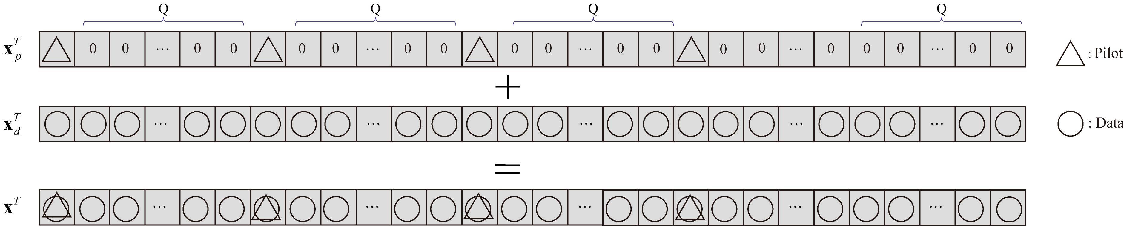
In the conventional embedded pilot scheme for AFDM, there are null guard samples placed on both sides of each pilot to ensure no interference between pilot and data signals, which results in a low SE. To increase the SE, we propose the superimposed pilot scheme, whose structure is shown in Fig. 1. In our proposed scheme, we eliminate the guard samples to allow full data transmission and place the pilots on top of the data signal in the DAFT domain. Therefore, the transmitting signal , formed by superimposing the pilot signal and the data signal , is given by
| (10) |
We define the pilot power as and data power as , such that and . Theoretically, we can insert full pilots over the whole DAFT domain, which means all elements of are non-zero. However, as will be explained in the next subsection the interference between pilots will arise, which might deteriorate the channel estimation performance. Therefore, to circumvent this issue, we suggest to place multiple equally spaced pilots with a spacing of at least , such that the element of satisfies
| (11) |
where and denotes the total number of superimposed pilots.
III-B Channel Estimation
Since there are at most channel paths, the received signal can be written as
| (12) |
where . The values of the delay index and the Doppler shift index associated with index are given by
| (13) |
and
| (14) |
respectively. The received signal vector in (12) can be expressed in a more compact form as
| (15) |
where and . The channel state information (CSI) vector has a mean of and a covariance matrix of . The matrices and , which contain the pilot vector and the data vector , respectively, can be obtained as
| (16) | |||
| (17) |
Lemma 1: The mean and covariance matrix of the random matrix are and , respectively.
Proof:
See Appendix A. ∎
The pilots and data are mixed in the received vector , causing the pilot-data interference. However, the data and pilots are statistically independent. Therefore, we can treat as part of the effective noise in the process of channel estimation. Furthermore, we define as the effective noise in the channel estimation.
Lemma 2: The vector has a mean of and a covariance matrix of
| (18) |
Proof:
See Appendix B. ∎
Given the statistics of the channel and effective noise, the minimum mean square error (MSE) estimate can be readily obtained as [8]
| (19) |
Lemma 3: To minimize the MSE , the column vectors of the matrix should form a set of orthogonal bases. This means for any integer , the following condition should hold
| (20) |
This condition ensures that the columns of are orthogonal to each other. In our proposed superimposed pilot scheme, the interval of two adjacent pilots, namely , is carefully chosen such that all column vectors in are orthogonal to each other.
Proof:
See Appendix C. ∎
To alleviate the interference for channel estimation resulting from the data and noise, we introduce a threshold criterion to estimate . Therefore, if we define a path indicator vector , where indicates whether a path associated with exists or not, we have
| (21) |
The value of influences the channel estimation performance. When is relatively large, some existing channel paths with a marginal gain may be missed. On the contrary, when is relatively small, some non-existent paths will be erroneously included due to data and noise. According to our extensive simulations, the optimal performance is achieved when is set as . This is in consistent with the result reported for OTFS channel estimation in [5].
III-C Data Detection
After obtaining the estimated CSI vector , we can now cancel the interference caused by the pilot signal for data detection as
| (22) |
where . Assuming the channel estimation is perfect, the received signal associated with the data can be approximately derived as
| (23) |
Since the matrix is typically sparse, we can adopt the message passing (MP) algorithm that offers low complexity.
III-D Iterative Channel Estimation and Data Detection
Due to the mutual interference between data and pilot signals, both the channel estimation and data detection are imprecise. To achieve more precise estimation, we resort to the iterative interference cancellation. Let , and denote the path indicator vector, channel estimation and data detection after the -th iteration, respectively. In the -th iteration, the CSI vector can be estimated by
| (24) |
where . We compare the elements of with the threshold to obtain and . Finally, can be estimated from via the MP algorithm after the -th iteration.
IV Simulation Results
In this section, we consider the AFDM system with and quadrature PSK. The maximum Doppler shift index , and the maximum delay index The number of channel paths is Each channel path has a different delay index and random Doppler index chosen from Each channel coefficient follows the distribution . The noise variance is set to dBm. The data signal-to-noise ratio (SNR) for transmission and pilot SNR for channel estimation are defined as and , respectively. Following [7], we set dB. The simulation results are obtained from more than independent channel realizations.
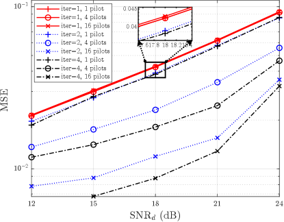
In Fig. 2, we illustrate the MSE performance. We consider the different numbers of iterations and superimposed pilots. It is observed that when the number of pilots is fixed, the MSE performance is improved as the number of iterations increases. This result confirms the effectiveness of our iterative algorithm. Furthermore, the increasing MSE performance with 4 and 16 pilots are more noticeable than that with a single pilot. In other words, as the pilot number increases, the channel estimation performs better and the effect of the iterative algorithm is more obvious. The results confirm multiple superimposed pilots with a reasonable placement achieve better performance in channel estimation.
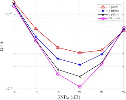
In Fig. 3, we present the uncoded bit error rate (BER) performance based on the MP detector with 2 iterations. Two interesting findings emerge from the figure. Firstly, as the number of pilots increases, the minimum BER for each curve decreases when 21 dB. This further confirms the benefit of our superimposed pilot scheme, and the fact there is an optimal power allocation for the pilot and data signals. Secondly, for each BER curve, as the increases for the range of dB, the BER decreases because the noise effect decreases. However, as the increases when dB, the BER performance deteriorates with the increasing . This phenomenon occurs because the pilot signal power is fixed. As the increases, there is more interference between the data and pilot signals which causes the inferior channel estimation presented in Fig. 2, leading to the degraded BER performance in Fig. 3.
V Conclusion
We have proposed an AFDM channel estimation scheme with superimposed pilots, aiming to increase the SE by superimposing data and pilots in the DAFT domain as well as to minimize the channel estimation MSE by ensuring at least guard intervals between two adjacent pilots. We have shown through rigorous derivations that our proposed scheme can effectively minimize the channel estimation MSE when the pilot signal power is fixed. Simulation results have demonstrated that both the MSE and BER performance are improved as the number of pilots increases. For future work, we will extend our proposed scheme to multi-input-multi-output and/or multi-user systems.
APPENDIX A
The random matrix satisfies
| (25) |
and
| (26) |
where
APPENDIX B
Since the data signal is statistically independent of the noise , we can express the covariance matrix of as
| (27) |
As proved in[10], if a random matrix has the covariance , for any Hermitian matrix it follows that . Since , the first term of the right hand side of (27) can be calculated as
| (28) |
Substituting (APPENDIX B) and the covariance matrix of into (27), we arrive at (18).
APPENDIX C
The covariance matrix of can be calculated as [11]
| (29) |
where the second term can be omitted as . The MSE of the channel estimation is thereby given by
| (30) |
Note that the trace of is given by
| (31) |
Also note that for a square matrix , the trace of is equal to the sum of its eigenvalues, namely , where is the -th eigenvalue of . If is invertible, then are the eigenvalues of . We define as the eigenvalue of . According to (31), the sum of the eigenvalues is fixed. Minimizing the trace of is equivalent to minimizing . Therefore, all the eigenvalues need to be identical. Since has equal diagonal elements, all the column vectors in should be orthogonal to each other. Let us consider two arbitrary column vectors and in , where . The (,)-th entry of can be expressed as
| (32) |
Therefore, can be written as
| (33) |
where
| (34) |
On the other hand, the inner product between and can be expressed as
| (35) |
Since and null guard samples are placed on both sides of each non-zero in , the value of is always zero when . Equation (35) can be thereby simplified as when .
References
- [1] W. Saad, M. Bennis, and M. Chen, “A vision of 6G wireless systems: applications, trends, technologies, and open research problems,” IEEE Netw., vol. 34, no. 3, pp. 134–142, May 2020.
- [2] R. Hadani, S. Rakib, M. Tsatsanis, A. Monk, A. J. Goldsmith, A. F. Molisch, and R. Calderbank, “Orthogonal time frequency space modulation,” in Proc. IEEE Wireless Commun. Netw. Conf. (WCNC), San Francisco, CA, USA, Mar. 2017, pp. 1–6.
- [3] S. K. Mohammed, “Derivation of OTFS modulation from first principles,” IEEE Trans. Veh. Technol., vol. 70, no. 8, pp. 7619–7636, Mar. 2021.
- [4] A. Bemani, N. Ksairi, and M. Kountouris, “Affine frequency division multiplexing for next generation wireless communications,” IEEE Trans. Wireless Commun., vol. 22, no. 11, pp. 8214–8229, Nov. 2023.
- [5] P. Raviteja, K. T. Phan, and Y. Hong, “Embedded pilot-aided channel estimation for OTFS in delay-Doppler channels,” IEEE Trans. Veh. Technol., vol. 68, no. 5, pp. 4906–4917, Mar. 2019.
- [6] W. Yuan, S. Li, Z. Wei, J. Yuan, and D. W. K. Ng, “Data-aided channel estimation for OTFS systems with a superimposed pilot and data transmission scheme,” IEEE Trans. Wireless Commun. Lett., vol. 10, no. 9, pp. 1954–1958, Jun. 2021.
- [7] Y. Kanazawa, H. Iimori, C. Pradhan, S. Malomsoky, and N. Ishikawa, “Multiple superimposed pilots for accurate channel estimation in orthogonal time frequency space modulation,” in Proc. 2023 IEEE 98th Vehicular Technology Conference (VTC2023-Fall), Hong Kong, China, Oct. 2023, pp. 1–5.
- [8] H. B. Mishra, P. Singh, A. K. Prasad, and R. Budhiraja, “OTFS channel estimation and data detection designs with superimposed pilots,” IEEE Trans. Wireless Commun., vol. 21, no. 4, pp. 2258–2274, Sept. 2022.
- [9] H. Yin and Y. Tang, “Pilot aided channel estimation for AFDM in doubly dispersive channels,” in Proc. 2022 IEEE/CIC International Conference on Communications in China (ICCC), Sanshui, Foshan, China, Aug. 2022, pp. 308–313.
- [10] P. Singh, H. B. Mishra, A. K. Jagannatham, and K. Vasudevan, “Semi-blind, training, and data-aided channel estimation schemes for MIMO-FBMC-OQAM systems,” IEEE Trans. Signal Process., vol. 67, no. 18, pp. 4668–4682, Jul. 2019.
- [11] S. M. Kay, Fundamentals of Statistical Signal Processing: Estimation Theory. Prentice-Hall, Inc., 1993.