Calculating the spin memory loss at Cumetal interfaces from first principles
Abstract
The role played by interfaces in metallic multilayers is not only to change the momenta of incident electrons; their symmetry lowering also results in an enhancement of the effects of spin-orbit coupling, in particular the flipping of the spins of conduction electrons. This leads to a significant reduction of a spin current through a metallic interface that is quantitatively characterized by a dimensionless parameter called the spin memory loss (SML) parameter, the interface counterpart of the spin-flip diffusion length for bulk metals. In this paper we use first-principles scattering calculations that include temperature-induced lattice and spin disorder to systematically study three parameters that govern spin transport through metallic interfaces of Cu with Pt, Pd, Py (permalloy) and Co: the interface resistance, spin polarization and the SML. The value of for a CuPt interface is found to be comparable to what we recently reported for a AuPt interface [Gupta et al., Phys. Rev. Lett. 124, 087702 (2020)]. For CuPy and CuCo interfaces, decreases monotonically with increasing temperature to become negligibly small at room temperature. The calculated results are in good agreement with currently available experimental values in the literature. Inserting a Cu layer between Pt and the Py or Co layers slightly increases the total spin current dissipation at these “compound” interfaces.
I Introduction
Since the discovery of giant magnetoresistance (GMR) in magnetic multilayers [1, 2, 3], interfaces have been recognized to play an essential role in the observation of many spintronics phenomena including spin-transfer torque [4, 5, 6, 7, 8, 9, *Ralph:jmmm08, 11, 12], the spin Hall effect (SHE) [13, 14, 15, 16, 17, 18, 19], spin pumping [20, *Tserkovnyak:prb02b, *Tserkovnyak:rmp05, 23, 24, 25, 26, 27, 28], the spin Seebeck effect [29, 30, 31], etc. In particular, the flux of spin angular momentum carried by a spin-polarized current of electrons or by a pure spin current may be significantly reduced at an interface. This loss of spin flux [32] is described in terms of a dimensionless parameter called the spin memory loss (SML) [33] and is confirmed in many experimental studies [34, 35, 36]. When spin transport parameters such as the spin Hall angle and the spin-flip diffusion length (SDL) are being evaluated [37, 38, 39, 40, 41, 42], it becomes critically important to know its numerical value. Neglecting it can lead to severely underestimated values of the SDL , which in turn influences the estimated values of the spin Hall angle [27, 43, 44, 45].
In semiclassical transport theory [46], the transport of a current of spins through an interface is described in terms of an interface resistance and the spin asymmetry , as well as the SML . The main way in which these interface parameters are determined is by measuring the GMR in a so-called current-perpendicular-to-the-plane (CPP) configuration. This technique is limited by the small value of the interface resistance between two metals (and its spin dependence) compared to those of typical leads. This problem can be overcome by reducing the sample cross section [47, *Gijs:ap97], or by using superconducting leads [49, *Bass:jmmm99]. At the low temperatures dictated by the superconducting transition temperatures of lead materials like Al or Nb, transport is dominated by disorder, such as interface roughness about which little is usually known for specific samples. Studies based on first-principles scattering theory can model many types of interface disorder [51, 8, 52, 53, 54] as well as temperature-induced bulk disorder [55, *LiuY:prb15] and thereby shed light on the SML and its relationship with microscopic scattering mechanisms [57]. A number of theoretical studies of the SML have recently been reported for interfaces between nonmagnetic (NM) materials [58, 59, 57] and between ferromagnetic (FM) and NM materials [60, 57, 61, 62] with a strong focus on interfaces between the transition metal Pt and another metal.
Pt is an important NM metal in spintronics because of its large spin-to-charge conversion efficiency. It is widely used to generate spin currents via the SHE and to detect spin currents via its inverse, the ISHE. Pt (and Pd) have very high densities of states at the Fermi energy and are relatively easily magnetized [63, 64] by proximity to a magnetic material [65, 66]. To avoid this happening while incurring minimal attenuation of the spin current, a thin Cu spacer layer is frequently inserted between Pt and magnetic materials [67, 68, 69] making it of interest to study such “compound” interfaces. Because of its long SDL that is estimated to be hundreds of nanometers at room temperature [36], Cu is widely used in nonlocal spin valves as a transport channel for a diffusive spin current [70, 71, 72, 73, 40, 74, 75]. In such studies, the important interfaces are CuNM and CuFM interfaces where NM is usually Pt or Pd and FM is Py (permalloy, Ni80Fe20) or Co. Because of the difficulty of estimating the SML at interfaces involving Cu it is often simply neglected.
In this paper, we present a systematic study of the transport parameters , and for interfaces comprising Cu and Pd, Pt, Co and Py using first-principles relativistic scattering calculations [76, *Starikov:prb18] that take into account temperature-induced lattice and spin disorder [55, *LiuY:prb15] as well as alloy disorder [78, *YuanZ:prl14] and lattice mismatch [43, 57, 62]. The SML parameters for CuPy and CuCo interfaces are found to decrease monotonically with increasing temperature and become negligibly small at room temperature. Inserting a thin Cu layer between Pt and Py or Co layers increases the total spin current reduction at the compound PtCuFM interface slightly, because of the nonnegligible SML at the CuPt interface.
The rest of this paper is organized as follows. In Sec. II, we briefly summarize the theoretical methods and provide some technical details of the calculations. The main results are presented and discussed in Sec. III where we begin by estimating the SDL of Cu, which must be known before we calculate the SML for Cumetal interfaces. This is followed by the results for CuPt, CuPd, CuPy and CuCo interfaces and their dependence on temperature and interface atomic mixing. A brief summary is given in Sec. IV. In Appendix A, the formalism required to determine the SML for NMFM interfaces using a bilayer structure is derived and it is shown to yield the same results for PtPy interface parameters as were obtained for a PtPyPt trilayer in [62].
II Theoretical methods and computational details
Most transport experiments in the field of spintronics are interpreted in terms of parameters that are defined in semiclassical transport theory [46]. A typical example is the Valet-Fert model which is used to describe the results of CPP-MR experiments [80, 81] using the bulk transport parameters (resistivity), (conductivity asymmetry), and (SDL) together with the corresponding three interface parameters , and . While the calculation of bulk transport parameters using first-principles scattering theory has already been documented [77, 45], determining the interface parameters is less trivial. In this section, we present the formulation [57] that we use to extract the parameters from the first-principles calculations when combined with a “layer-averaged local current scheme” [45]. Further details of the formulation are provided elsewhere [82, 62]. The results of semiclassical transport theory that we will need are summarized in Sec. II.1. They are applied to an NMNM′ interface in Sec. II.2 and to an FMNM interface in Sec. II.3. Some technical details of the calculations are given in Sec. II.4.
II.1 Spin diffusion equation
In an axially symmetric layered structure, the current flow in the direction, perpendicular to the interfaces, is described by the spin diffusion equation [46]
| (1) |
where represents the SDL and is the spin accumulation defined as the difference between the spin-up and spin-down chemical potentials, . The spin-dependent chemical potential drives the corresponding current density according to Ohm’s law
| (2) |
where is the spin-dependent bulk resistivity and it is assumed that the two spin channels are weakly coupled. The general solutions of (1) and (2) are
| (3) |
and
| (4) |
respectively, where the coefficients and are determined by appropriate boundary conditions. Here is the bulk spin asymmetry, denotes the total current density and is the total resistivity given by . We define the normalized spin-current density to be which can be written
| (5) |
Equation (5) can be used together with the spin current density calculated from first principles to extract and [45] while is determined independently from the scattering matrix using the Landauer formula [76, 77].
II.2 NMNM′ interfaces
For a NM metal or alloy with an equal number of spin-up and spin-down electrons, , and (5) simplifies to
| (6) |
If a fully polarized spin current is injected from an artificial half-metallic left lead () into a diffusive NMNM′ bilayer so , then the spin current will decay in both nonmagnetic metals and, provided the bilayer is sufficiently thick, will vanish at the right lead, . On each side of the interface, (6) can be used to fit the calculated to obtain the corresponding SDL for each metal, NM, NM′. Extrapolation of the fitting curves to the interface yields two different values for the spin current at the interface, where is a positive infinitesimal. The corresponding discontinuity, shown in Fig. 3, represents the interface SML.
In the absence of appropriate boundary conditions for a NMNM′ interface, we follow [35, 36, 43, 27] and model the interface (I) as a fictitious bulklike material with a finite thickness , a resistivity and SDL . By doing so, the NMNM′ bilayer becomes a NMINM′ trilayer in which the spin current and spin accumulation are everywhere continuous. Taking the limit , we recover the conventional interface resistance as well as the SML ,
| (7) |
where the cross sectional area should not be confused with the disposable constant in (6). In this way, the discontinuity at the interface is naturally included in the semiclassical spin diffusion theory. The result of imposing continuity on and and then taking the limit is
| (8) |
By calculating the bulk parameters and and the interface resistance independently, only the single unknown parameter needs to be determined from (8) which can be straightforwardly solved numerically. The calculation of using the Landauer-Büttiker formalism will be presented in Sec. III.2.
II.3 FMNM interfaces
Unlike NM metals for which , the asymmetry between the spin-up and spin-down conducting channels in a FM metal leads to saturating to a finite value well inside the ferromagnet, on a length scale of . We therefore construct a symmetric NMFMNM trilayer with the origin at the centre of the FM layer and inject an electric current from a NM lead imposing the boundary conditions . The calculated spin current in the FM metal can be fitted using (5) to extract , [45] and [57, 62]. In the NM metal, the fitting using (6) is still applicable resulting in and where because of the symmetry and without loss of generality, we just consider the rightmost FMNM interface. Just as we did for the NMNM′ interface, we transform the FMNM interface into an FMINM trilayer with a finite thickness of the interface region. The only difference is that the FMNM interface resistance is spin dependent and the parameter is introduced to characterize the spin polarization.
Taking the limit yields the interface discontinuity and the analysis [62] results in two implicit equations
| (9a) | |||||
| (9b) | |||||
which can be solved to yield the remaining unknown variables and [57, 62].
The boundary conditions are appropriate for structures with NM materials like Pt, for which is short, embedded between nonmagnetic leads [62]. When is as long as it is for NM=Cu, it is not possible to treat a thickness of the NM metal so large that the spin current can be assumed to have decayed to zero at the interfaces with the leads. Instead, we consider the injection or detection of a spin-polarized current corresponding to the boundary conditions or equal to the current polarization which can have an arbitrary value in the range . For simplicity, a half-metallic ferromagnetic lead is considered in Appendix A, where is explicitly illustrated. Within the accuracy of the calculations, both sets of boundary conditions lead to the same interface parameters.
II.4 Computational details
Our starting point is an electronic structure for the layered metallic system of interest, calculated self-consistently within the framework of density functional theory [83, 84]. The electronic wave functions are expanded in terms of tight-binding linearized muffin-tin orbitals [85, *Andersen:85, *Andersen:prb86] in the atomic spheres approximation (ASA) [88]. We use the local density approximation with the exchange-correlation functional parameterized by von Barth and Hedin [89]. Transport is addressed by solving the quantum mechanical scattering problem for a general two-terminal geometry using Ando’s wave-function matching method [90] implemented [54, 91] with the tight-binding muffin-tin orbital basis. The conductance is calculated directly from the scattering matrix for the scattering region embedded between semi-infinite ballistic leads [92]. The full quantum-mechanical wave functions are explicitly determined throughout the scattering region from which we calculate position dependent charge and spin currents [93, 45]. Spin-orbit coupling was neglected in calculating the self-consistent atomic potentials but included in the transport calculations [77].
Temperature-induced lattice and spin disorder, alloy disorder and lattice mismatch can be efficiently modelled in “lateral supercells” that assume a measure of periodicity in the directions transverse to the transport direction [77, 45]. The lattice constant of Pt is Å, that of Pd just 0.8% smaller, Å [94]. Those of Py, Co and Cu are about 10% smaller but quite similar with Å [77], Å [95] and Å [94]. For the CuPt, CuPd, PyPt and CoPt interfaces studied here, an 88 interface unit cell of (111) Cu, Py or Co is chosen to match to a 22 interface unit cell of Pt or Pd (neglecting the 0.8% difference) which allows all materials to be kept fcc. The two-dimensional Brillouin zone of the 88 supercell of (111) Cu is sampled using points and the same mesh density is used for all the transport calculations. Py is chosen to have its equilibrium lattice constant. To study CuPy and CuCo interfaces, Cu must be compressed slightly to match Py, respectively Co; as shown for Au in [95, 82], this changes the Fermi surface, and hence the transport properties, of the noble metal negligibly. The alloy disorder of bulk Py is modelled by randomly populating lateral supercell sites with Fe and Ni atomic sphere potentials subject to the required stoichiometry [77], where the atomic potentials of the alloy are calculated self-consistently within the coherent potential approximation [96, 97]. Interface disorder arising from interface mixing (see Sec. III.4) is modelled as a number of layers of interface alloy [51, 8, 52, 53, 54, 57, 82].
Temperature-induced disorder is modelled in the adiabatic approximation using a “frozen thermal lattice disorder” scheme with atoms displaced at random from their equilibrium lattice positions with a Gaussian distribution of displacements. The root mean square displacement characterizing the distribution is chosen so that the resistivity of the NM metal at a finite temperature is reproduced as detailed in [55, *LiuY:prb15]. For example, we need a value of to reproduce the room-temperature resistivity of bulk Cu, . This value of may be compared to values obtained by populating phonons at 300 K () [56], from room temperature molecular dynamics simulations () [98] or from 160 K X-ray diffraction measurements () [99]. For a FM metal, not only are the atom positions influenced by temperature but also their magnetic ordering. We use a simple Gaussian model of spin disorder parameterized to reproduce the experimental magnetization of the ferromagnet at a given temperature, combined with lattice disorder so that together they reproduce the experimental resistivity as discussed in [55, *LiuY:prb15, 77]. This spin disorder is equivalent to the Fisher distribution [100] at low temperature when the tilting angle measured from the global quantization axis is small [77]. The numerical convergence has been extensively examined with respect to the maximum angular momentum in the basis, size of the lateral supercell, -mesh sampling of the two-dimensional Brillouin zone, the number of random configurations of lattice and spin disorder, as well as the influence of the three-center integrals in the spin-orbit interaction [77, 45, 62, 82]. Compared to calculations of the conductance, we find that more configurations are needed to reduce the error bars on the local currents to acceptable levels.
III Results and discussion
Before we calculate the SML for Cumetal interfaces, the SDL of bulk Cu is estimated in Sec. III.1. CuPt and CuPd interfaces are considered in Sec. III.2, followed by CuPy and CuCo interfaces in Sec. III.3. The effect of interface atomic mixing for materials with similar atomic volumes is examined in Sec. III.4 for CuCo and CuPy interfaces. A compound interface obtained by inserting atomic layers of Cu between FM and Pt is studied in Sec. III.5.
III.1 Estimating
In the semiclassical theory commonly used to describe spin transport, five bulk parameters , , , , and three interface parameters , and are required to describe transport through the FMNM interface of a bilayer, while the bulk and interface spin polarizations and vanish for an interface between two NM metals. The numerical techniques required to determine the resistivity of a NM or FM metal, as well as the SDL of most transition metals and alloys using scattering theory are well documented [55, 43, 56, 77, 45]. For free-electron like metals like Cu, Ag and Au, may be as large as several hundred nanometers to micrometers and a quantitative estimation requiring the length of the scattering region to be longer than 3-4 becomes computationally very demanding [101]. To estimate we therefore calculated and simultaneously at elevated temperatures, as a function of the root-mean-square-displacement , to determine the product that for the Elliott-Yafet mechanism of spin relaxation should be temperature independent and then used the confirmed linear relationship to extrapolate to the required lower temperature.

is plotted in Fig. 1 as a function of the simultaneously determined conductivity for a number of values of (solid squares); the approximate linearity indicates that the Elliott-Yafet mechanism [102, 103] is dominant [101]. The product is obtained from linear least squares fitting. This linear relationship is extrapolated to the lower temperatures corresponding to the documented conductivity of bulk Cu at 100, 200, 300 and 400 K which are shown as the empty circles in Fig. 1. In particular, corresponding to the room temperature resistivity cm, we estimate a value of nm.
III.2 CuPt and CuPd interfaces

We begin by examining the spin memory loss at the CuPt interface that commonly appears in nonlocal spin-valve, spin-pumping and spin-Seebeck experiments. We then compare our results when Pt is replaced by the isoelectronic and isostructural but lighter element Pd.
Before addressing the SML, the CuPt interface resistance needs to be determined using the standard Landauer-Büttiker formalism [92, 104]. As sketched in Fig. 2(a), we do this by sandwiching a symmetric, diffusive CuPtCu trilayer between ballistic Cu leads in a two-terminal scattering configuration where element specific parameters are used to reproduce the room-temperature resistivities of bulk Cu and Pt, respectively. The total calculated area resistance product for a cross-section of the scattering geometry can be written as
| (10) | |||||
where denotes the Sharvin conductance of the ballistic Cu leads, is the resistance of the interface between the ballistic Cu lead and diffusive Cu, with nm is the resistance of a length nm of diffusive Cu 111An explicit numerical check showed that nm is enough to reproduce the linear dependence of the resistance on the Cu length and therefore a longer would not alter the final value of the SML that we are interested in., is the resistance of a length of diffusive Pt and is the sought-after CuPt interface resistance. By repeating the calculations without the central Pt layer, we obtain the contribution from the first three terms on the right hand side of (10) separately. This is subtracted from the total resistance in (10) leaving us with that is plotted in Fig. 2(b) as a function of where each data point is obtained by averaging over seven configurations of random thermal disorder. The slope of the linear least squares fit reproduces the resistivity of bulk Pt at room temperature while the intercept results in the interface resistance .

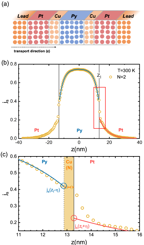
[45, 101], and have now been calculated, and have their experimental values by construction, leaving just and to be determined before can be evaluated using (8). To do so, we inject a fully polarized spin current from an artificial half-metallic Cu lead [77, 45] into a diffusive, room temperature (RT: 300 K) Cu(10 nm)Pt(30 nm) bilayer. The -dependent spin current density is plotted in Fig. 3, where each data point corresponds to averaged over an atomic layer and over twenty random configurations of thermal lattice disorder. On both sides of the interface, the spin current can be fitted very well using (6) as shown by the solid orange and red lines in Fig. 3. As expected from the large value of , the spin current decays extremely slowly in Cu, as shown in the inset. To reduce the uncertainty from fitting, we use the room temperature value nm yielding very good agreement with the calculated data. The spin current entering Pt exhibits an exponential decay which can be characterized by a value of nm consistent with the value nm reported previously in [57]. The fitted semiclassical description of the spin current exhibits a substantial discontinuity at the CuPt interface corresponding to the interface SML, Fig. 3. Using the values and obtained by extrapolation, , and , we finally estimate the SML to be for the CuPt interface. This value of is very close to and only slightly smaller than the value of 0.81 we reported for the relaxed AuPt interface and substantially larger than the value 0.62 we found for the compressed AuPt interface [57] indicating the importance of taking lattice mismatch into account, Table 1.
By repeating the complete procedure for the CuPd interface and neglecting the 0.8% smaller lattice constant of Pd, we find at 300 K that is smaller than the SML for the CuPt interface because of the weaker spin-orbit interaction in Pd. This value for the CuPd interface is also consistent with the SML values of 0.43 and 0.63 calculated for the “commensurate” (with Au compressed to match to Pd) and “incommensurate” AuPd interfaces [57], respectively. We attribute this agreement to the very similar electronic structures of Cu and Au, where the free-electron-like band dominates transport at the Fermi level; the filled 3 or 5 bands are well below the Fermi energy so the difference in spin-orbit coupling strength between Cu and Au does not play a significant role.
| Pd | Pt | |||
| Compressed | Relaxed | Compressed | Relaxed | |
| Cu | — | — | ||
| Au [95] | ||||
| T(K) | Method | Ref. | |||
| CuPt | 4.2 | CPP-MR | [81] | ||
| —— | 0.95 | 7 | CPP-MR | [106] | |
| —— | 0.89 | 295 | CPP-MR | [106] | |
| 300 | This work | ||||
| CuPd | 4.2 | CPP-MR | [81] | ||
| 0.76 | 0.43 | 0 | Ab initio | [58] | |
| 300 | This work | ||||
We compare our calculated interface resistances and SML parameters with experimental and theoretical values available in the literature in Table 2. For the CuPt interface, our calculated values of and are somewhat smaller than the experimental values. Experimentally, the influence of temperature on the SML of a NMNM′ interface is found to be weak [106] which is consistent with our theoretical findings [43, 57]. This is because the main scattering mechanism at the interface is the abrupt variation in the atomic potentials experienced by conduction electrons [43]. For the CuPd interface, the value we calculate for is in perfect agreement with that calculated by Belashchenko et al. [58] but is larger than the only reported, low-temperature experimental value [81]. To make more progress, structural properties need to be correlated with transport measurements. We identify a lack of structural characterization of interfaces on the atomic level as a major stumbling block to developing more comprehensive understanding. The theoretical description we have presented can be applied to considerably more complex structural models.
III.3 CuFM interfaces
We proceed to study the SML at the interfaces between Cu and the FM metals Py and Co. The exchange interaction in FM metals automatically generates a spin polarization of the conduction electrons so that we do not need to artificially inject a spin-polarized current from the half-metallic lead as in the previous section.
III.3.1 CuPy
Instead, we consider a Py thin film that is sandwiched between two diffusive Cu films, as sketched in Fig. 4(a). We pass an electric current through this multilayer and plot the calculated spin current as a function of position in Fig. 4(b). According to (5), it saturates to the value of the conductivity asymmetry sufficiently deep into Py on a length scale of . The saturated plateau value decreases with increasing temperature corresponding to the suppression of by magnons [56]. A lower but nonzero spin polarization is seen in the diffusive Cu layers. The spin current in Py and Cu can be fitted using equations (5) and (6), respectively, as shown by the lines in Fig. 4. Unlike the corresponding PtFMPt case [57, 62], the spin current does not show a significant discontinuity at the PyCu interface. A magnified plot about the right interface in Fig. 4(c) shows that a very small discontinuity appears only at low temperature. In particular, the quantitative calculation results in at 300 K. After taking into account all of the uncertainties in the calculated transport parameters entering (9), we obtain an estimate of 0.09 as the upper limit of for the CuPy interface at room temperature. The interface spin asymmetry coefficient is estimated to be , Table 3. This high value can be understood in terms of the very similar majority-spin potentials of fcc Cu and of Fe and Ni in fcc Py [77], where the majority-spin 3 bands are calculated to be filled. The CuPy interface then scatters majority-spin electrons only very weakly. In contrast, the minority-spin potentials (and electronic structures) change abruptly at the interface resulting in strong scattering. A highly asymmetric interface conductance is the result.

The very long SDL of Cu introduces two technical difficulties in the above calculations: (i) the value of we use is extrapolated from high temperatures and (ii) the diffusive Cu layers attached to Py are not thick enough for the boundary condition to be satisfied as required by the formulation of Sec. II.3.
We first examine the robustness of our computational framework with respect to the value of . In addition to using the value of nm estimated by extrapolation in Fig. 1, we also use literature values of , found in room-temperature experiments and listed in Table 3, to calculate and for the CuPy interface. Using these values in (9) always yields a vanishingly small SML at room temperature. This is insensitive to the particular value of used and only its upper bound shows a slight variation. The value of we estimate is relatively sensitive to the value of used; a longer results in a larger value of . This is because the normalized spin currents on the Cu side and on the Py side of the interface have values between 0 and 1 and the large product in (9) must be compensated by the factor to avoid exceeding these bounds. In particular, we see that in the limit , . Therefore, a reasonable value of is needed to estimate , the interface resistance asymmetry.
| T(K) | Method | (nm) | |||
|---|---|---|---|---|---|
| 300 | CPP-NW [107] | 3614 | 0.43 | 0.420.35 | |
| 300 | LNL/M [108] | 0.850.03 | |||
| 293 | CPPNP [109] | 17040 | — | 0.910.06 | |
| 293 | LNL/C [70, 110] | 35050 | 10 | 0.960.02 | |
| 293 | LNL/M; | ||||
| LNL/+ [111] | 500 | 11 | 0.970.01 | ||
| 293 | LNL/M [112] | 700 | 15 | 0.980.01 | |
| 300 | This work | 502 | 9.01.0 | 0.970.01 |
The large value of nm makes it impossible to construct a scattering region long enough for a CuFMCu trilayer to satisfy the boundary condition in currently practical calculations. We therefore examine the values of and we obtain when we apply a different boundary condition that can be strictly complied with in practice. By analogy with the injection of a fully polarized current into the CuPt bilayer, we can inject a fully spin-polarized current with the same polarization sign as Py into a CuPy bilayer; this then satisfies the condition . When the thickness of Py is much larger than its SDL, the spin current approaches its bulk polarization at . Following the same procedure we used for the NMNM′ interface in Sec. II.2, we derive the semiclassical diffusion equations for spin transport in a diffusive NMFM bilayer in Appendix A to eventually arrive at the two equations
| (11a) | |||||
| (11b) | |||||
The spin current calculated in the CuPy bilayer with the boundary condition is plotted in Fig. 5. Using (6) to fit the data calculated in Cu (solid orange line) and (5) for those in Py (solid blue line) allows us to find the asymptotic values at the interface. Since all the bulk parameters , , , , and as well as the interface resistance were already determined independently, equations (11) can be solved resulting in and . Here the uncertainties in and are obtained by considering the uncertainties in all the other parameters in (11). This independent check with an alternative boundary condition confirms the values and extracted from Fig. 4 using the trilayer structures. It is worth noting that the thickness of Py in the CuPy bilayer must be large enough to satisfy the boundary condition . Otherwise the Cu right-hand lead may influence the values of calculated near the CuPy interface. (Indeed, the influence of the right-hand lead can be seen in the incipient deviation of from for nm in Fig. 5.)

The temperature dependence of , and is shown in Fig. 6 for the CuPy interface. All three parameters decrease monotonically with increasing temperature and this decrease can be attributed to the stronger spin disorder of Py at higher temperature by analogy with our findings for the PtPy interface [57]. The electron scattering at the CuPy interface is strongly spin-dependent: the majority-spin channel is highly conductive and, without spin-orbit coupling or spin disorder, the minority-spin channel is much more resistive. Spin disorder allows the spins of conduction electrons to flip at the interface and hence reduces the transmission of majority-spin electrons. At the same time, it creates more transmission channels for minority-spin electrons. Because the minority-spin 3 bands are partially occupied for Py, their state density at the Fermi energy is very large so the increase of the minority-spin conductance is greater than the decrease of that for the majority spins. Therefore the total transmission probability increases with increasing spin disorder; the interface resistance decreases. To confirm this, we repeat the T=200 K, 300 K and 400 K calculations for the CuPy interface with only lattice disorder and keeping the magnetic moments aligned with the global quantization axis. The values of we calculate are almost independent of temperature as shown in Fig. 6. We conclude that spin disorder is the main reason for the temperature-induced decrease of the interface resistance.
| T(K) | ||||
|---|---|---|---|---|
| CuPy | 100 | 0.500.01 | 0.980.01 | 0.160.05 |
| 200 | 0.470.02 | 0.980.02 | 0.110.05 | |
| 300 | 0.410.02 | 0.970.01 | 0+0.09 | |
| 400 | 0.340.04 | 0.960.01 | 0+0.08 | |
| CuCo | 300 | 0.450.03 | 0.950.02 | 0.110.04 |
The CuPy interface parameters we calculate at various temperatures are listed in Table 4. The low temperature (T=100K) value of that we calculate is in reasonable agreement with the low-temperature experimental value of 0.26 [113]. The discrepancy may be attributed to unknown microscopic interface disorder in the experimental samples. Accurate measurements of the interface resistance depend on being able to separate bulk and interface contributions clearly but these are usually strongly entangled [81]. The calculated value of is also larger than the experimental value [113]. Improved characterization of the experimental interface structures are necessary to make progress. The SML is approximately 0.160.05 at 100 K and becomes negligible at room temperature indicating that the CuPy interface is transparent to a spin current. As the interfacial counterpart of bulk spin-flip diffusion length, the SML arises microscopically from the spin-flip scattering at the interface, which is usually induced by the enhanced spin-orbit interaction owing to the broken translational symmetry. With increasing temperature, spin fluctuation in the FM provides an additional source of spin-flip scattering. Nevertheless, the temperature-induced spin fluctuation also lowers the spin polarization parameter in bulk [57, 62]. Overall, the calculated SML for CuPy exhibits a monotonic decrease with increasing temperature.


III.3.2 CuCo
We repeat the above calculations at room temperature replacing Py by Co which has a higher Curie temperature and no intrinsic alloy disorder. The calculated interface parameters are included in Fig. 6. A value of is found which can be compared with the low-temperature experimental value of [113] and previously calculated value of without spin-orbit coupling and thermal disorder [51]. We find a value of that is larger than the experimental value of [113]. The room temperature SML, , for the CuCo interface compares reasonably with the low-temperature experimental value [113]. The values of and we calculate for the CuCo interface are slightly larger than the corresponding values for the CuPy interface because of the greater order of Co. We found analogous results for PtPy and PtCo interfaces [57]. is nearly the same as indicating the strong spin-filtering effect of both interfaces.
III.4 Interface mixing
Even in the best experimental samples, the interfaces will almost certainly not be as well ordered as those we have considered so far. In the process of growing thin layers, the kinetic energy of the deposited atoms will lead to interface mixing, rendering the interfaces less sharp [81]. We model the mixing of an AB interface by completely mixing one (or two) layers on either side of the interface that then leads to two (or four) layers with the composition A50B50. The lattice and spin disorder is assumed to be unchanged, as are the atomic sphere potentials. The spin currents that result from these calculations for CuPyCu structures with intermixed interfaces are shown in Fig. 7(a). They are fitted in Py and Cu using equations (5) and (6), respectively and extrapolated to the PyCu interface at to determine on the Py side and on the Cu side, Fig. 7(a), lower panel. The interface resistance is determined in separate calculations and finally and are extracted by solving equations (9). The results are shown for both CuPy and CuCo interfaces in Fig. 7(b). is seen to increase monotonically with increasing thickness of the mixed interface layer because of the strong scattering by alloy disorder. The interface spin asymmetry parameter is not changed by the intermixing. The majority-spin potentials of Co, and of both Ni and Fe in Py, are perfectly matched to the potential of Cu while the minority-spin potentials all differ. For this reason, both CuPy and CuCo interfaces exhibit strong spin filtering and this effect is not significantly weakened by mixing the magnetic and Cu atoms.
The effect of interface mixing on the SML for CuPy and CuCo interfaces is complex. First, the stronger interface scattering by the interface alloy enhances the spin flipping, as we found for the nonmagnetic AuPt interface [57]. For a CuFM interface, alloying reduces the magnetic order on the FM side and this reduces the SML by analogy with the reduction we found for PtCo and PtPy interfaces on increasing the temperature [57]. Competition between the two effects results in the (slightly) nonmonotonic dependence of on the thickness of the interface alloy layer at CuPy and CuCo interfaces shown in Fig. 7(b). This nonmonotonic behavior is clearer for CuCo since Co has a higher degree of magnetic order than Py.
III.5 Inserting copper at a FMNM interface
Cu is commonly used in experiments as a spacer material between a heavy metal like Pt with a large spin susceptibility and a FM metal, to prevent magnetism being induced in Pt by the proximity effect. Because of its weak spin-orbit interaction and correspondingly long SDL, a thin layer of Cu is usually assumed to have no effect on a spin current thus making the interpretation of experiments simpler. However, though bulk Cu may have little effect on a spin current, insertion of a Cu layer between a FM metal and Pt replaces the singel FMPt interface with two different interfaces, namely, FMCu and CuPt interfaces whose effect on a spin current is, at best, poorly known. Here we consider Py and Co as typical FM metals and Pt as a typical heavy metal to investigate the influence of inserting Cu layers on the spin memory loss.
As shown schematically in Fig. 8(a), we calculate the spin current distribution at 300 K for a PtCuPyCuPt multilayer when a charge current is passed through it. The thickness of the Py (Pt) layers is 26 nm (25 nm) and we consider , 1 and 2 atomic layers of Cu. The spin current in the transport direction () that we calculate for a symmetric PtCu()PyCu()Pt multilayer is shown in Fig. 8(b) for . Both the saturated plateau in the center of Py and the vanishing spin current at the interfaces between Pt and the leads confirm that Py and Pt are sufficiently thick and satisfy the boundary condition . We fit using the spin diffusion equations in Py and Pt and use these fits to extrapolate on the Py side to the PyCu interface to calculate and on the Pt side to the CuPt interfaces to calculate , respectively as illustrated in the exploded plot in Fig. 8(c). The somewhat arbitrary choice of within the Cu insert has a negligible effect on the values of and that we extract because of the thinness of Cu. The SML determined in this way accounts for the spin-flipping at the “compound interface” between Py and Pt.
Using the above scheme, we calculate the interface parameters , and for PyCuPt and CoCuPt interfaces at room temperature and summarize the results in Fig. 9 and Table 5. The Cu insert increases to between 1.06 and , which is very close to the sum of the two interface resistances connected in series, . Because Cu is so thin and conductive, its contribution to can be neglected. The parameter is small for both the PyPt and CoPt interfaces but increases with increasing Cu thickness. This is because the PyCu and CoCu interfaces have strong spin filtering effects. The scattering rate for minority-spin electrons is enhanced by the Cu insert leading to an increase in . The dependence of and on the thickness of Cu is the same for both PyCuPt and CoCuPt interfaces.

| PyCu()Pt | 0 | 0.790.03 | -0.060.09 | 0.760.11 |
|---|---|---|---|---|
| 1 | 1.060.02 | 0.090.09 | 0.860.12 | |
| 2 | 1.110.01 | 0.140.07 | 1.000.14 | |
| CoCu()Pt | 0 | 0.820.05 | 0.000.08 | 0.770.13 |
| 1 | 1.110.01 | 0.120.03 | 1.120.16 | |
| 2 | 1.120.01 | 0.170.05 | 1.180.17 |
We finally consider the SML with and without the Cu insert. Without it, at room temperature. As shown in Table 5 and Fig. 9, inserting Cu increases slightly to for and to for compared to for the two separate interfaces. For the CoPt interface, the SML increases from to for and for . The sum of the room temperature SML values for the individual interfaces, , is substantially lower than the SML we find for the compound CoCuPt interface. Thus, contrary to the expectation that separating the FM and heavy metal should enhance the interface transparency for a spin current [114], we find that it increases the SML.
IV Conclusion
We have calculated the semiclassical spin transport parameters for CuPt, CuPd, CuPy and CuCo interfaces at finite temperature within the adiabatic approximation using first-principles scattering theory [77] and a recently developed planar-averaged local current scheme [45]. The dependence of the interface parameters on temperature and interface atomic mixing is studied systematically. The SML at a CuPt interface is comparable to what we found for an incommensurate AuPt interface in [57] which we attribute to the similarity of the free-electron-like electronic structures of the noble metals Cu and Au. For CuPy and CuCo interfaces, both the interface resistance and SML are found to decrease monotonically with temperature. The SML becomes negligibly small at room temperature. By analogy with the PtFM interfaces, the SML is larger for CuCo than for CuPy because unlike Py, Co does not have alloy disorder and has a higher Curie temperature. Inserting a thin layer of Cu in the PyPt or CoPt interfaces increases the SML. Since Cu is widely used as a transport channel in nonlocal spin valves, our calculated values of interface transport parameters for the CuNM and CuFM interfaces should be very useful reference data for experimental studies.
Where comparison can be made, the results we calculate are in reasonable agreement with published experimental values. The sophistication of our calculations is such that where discrepancies exist, the first issue that much be examined is the validity of the structural models we use. Our computer codes make it possible to examine many types of interface disorder but at present more information is required from experiment to motivate more extensive theoretical investigations than the present one. Where the experimental data were obtained from low-temperature models, the onus is on our experimental colleagues to provide us with information about the disorder that leads to diffusive behaviour at low temperatures.
Acknowledgements.
This work was financially supported by the National Natural Science Foundation of China (Grants No. 12174028 and No. 11734004), the Recruitment Program of Global Youth Experts and by the “Nederlandse Organisatie voor Wetenschappelijk Onderzoek” (NWO) through the research programme of the former “Stichting voor Fundamenteel Onderzoek der Materie,” (NWO-I, formerly FOM). K.G. acknowledges funding from the Shell-NWO/FOM “Computational Sciences for Energy Research” PhD program (CSER-PhD; nr. i32; project number 13CSER059). The work was also supported by the Royal Netherlands Academy of Arts and Sciences (KNAW).Appendix A The Valet-Fert formalism for a NMFM bilayer
The RT value of nm makes it possible to realize the boundary condition for PtFMPt scattering regions that can be handled in practical calculations [57, 62]. The large value of nm makes this impossible for CuFMCu raising doubts about the value of calculated in Sec. III.3. In this Appendix we derive semiclassical transport equations based on the Valet-Fert formalism for a NMFM bilayer with a spin-polarized current incident from the left lead for which the boundary condition is . Using this alternative boundary condition to determine the SML for CuFM interfaces yields the same numerical values of as the boundary condition. We demonstrate that the two different calculation schemes yield the same results within the numerical accuracy for a PtPy interface.
We follow the standard procedure used in the literature [33, 35] and treat the interface (I) as an artificial bulklike material with resistivity , SDL and finite thickness that are related to an interface resistance and SML as and . The general solutions (3) and (5) to the spin diffusion equations and Ohm’s law have the same forms in the NM, I (interface), and FM regions
| (12) | |||||
| (13) |
If a fully polarized spin current is injected from an artificial half-metallic left lead into a diffusive NMFM bilayer, one has the boundary condition , where the sign () indicates that the polarization is parallel (antiparallel) to the current polarization direction in the FM metal. Substituting this boundary condition at into (13) and considering in the NM metal, we find
| (14) |
The above equation can be substituted into (12) and (13) to eliminate the coefficients and . Eventually we arrive at the following relation between the spin accumulation and the normalized spin current in the NM metal
| (15) |
In the FM metal, the boundary condition results in . The other coefficient can be eliminated using (12) and (13) and the spin accumulation in the FM metal reads
| (16) |
Since the interface is replaced by an artificial bulklike material with a finite thickness , the spin accumulation and spin current are continuous everywhere. At the NMI boundary and at the IFM boundary , the spin accumulation and spin current are both continuous,
| (17) | |||||
| (18) | |||||
| (19) | |||||
| (20) |
(17) and (18) can be used to express the coefficients and as functions of the spin accumulation at the NMI and IFM boundaries as
| (21) | |||||
| (22) |
Substituting (21) and (22) into (19) and (20), we find two equations containing and at the boundaries and . The spin accumulation is eliminated using (15) and (16) and finally, we take the limit to arrive at equations (11) that only depend on spin currents
| (23a) | |||||
| (23b) | |||||
Here in (11) and similarly and we have already made use of the relations and .
For the special case , the NMFM interface becomes an NMNM′ interface and (23a) and (23b) reduce to
| (24a) | |||||
| (24b) | |||||
Eliminating from the above two equations, we obtain
| (25) |
PtPy bilayer
To examine the validity of extracting the SML and interface polarization for a NMFM interface with a fully polarized current injected from the NM side, we take PtPy as an example and compare the numerical results we find with those obtained by passing an unpolarized current through a NMFMNM trilayer structure [57, 62]. We construct a diffusive Pt(10 nm)Py(15 nm) bilayer at room temperature with thermal lattice and spin disorder. The lattice mismatch between the two fcc metals is accommodated using a supercell of (111) oriented Pt matched to a supercell of (111) Py. The bilayer is then sandwiched between Cu leads whose lattice constant is chosen to be the same as that of Py. The minority-spin (or majority-spin) potential of Cu in the left lead is artificially increased by 1 Rydberg so that all the incoming Bloch states have pure spin character and the charge current injected from the left Cu lead is fully spin-polarized. In the transport calculation, the 2D Brillouin zone of the matched lateral supercell is sampled using a -mesh corresponding to a sampling of a unit cell of fcc Py. The results we show are obtained by averaging over twenty random configurations of thermally disordered PtPy bilayer. Note that the Py is sufficiently thick that the right-hand lead does not affect at the PtPy interface plotted in Fig. 10.

The plane-averaged spin current we obtain for the PtPy bilayer is shown in Fig. 10. Using (13), it can be fitted piecewise in Pt (solid lines) and in Py (dashed lines) and the values required at the interface are obtained by extrapolating these fits. On injecting a spin current with positive polarization into Pt, (blue symbols and lines), we find and by extrapolation. Substituting these values into (23a) and (23b) together with the independently determined bulk parameters, , nm, , nm and , we finally obtain and . Injecting a spin current with negative polarization, (red symbols and lines), we find and yielding and . These values are consistent with the values calculated using the PtPyPt trilayer structure and within the error bars of the calculations [57, 62].
References
- Baibich et al. [1988] M. N. Baibich, J. M. Broto, A. Fert, F. Nguyen Van Dau, F. Petroff, P. Etienne, G. Creuzet, A. Friederich, and J. Chazelas, Giant Magnetoresistance of (001)Fe/(001)Cr Magnetic Superlattices, Phys. Rev. Lett. 61, 2472 (1988).
- Binasch et al. [1989] G. Binasch, P. Grünberg, F. Saurenbach, and W. Zinn, Enhanced magnetoresistance in layered magnetic structures with antiferromaganetic interlayer exchange, Phys. Rev. B 39, 4828 (1989).
- Parkin [1993] S. S. P. Parkin, Origin of enhanced magnetoresistance of magnetic multilayers: Spin-dependent scattering from magnetic interface states, Phys. Rev. Lett. 71, 1641 (1993).
- Slonczewski [1996] J. C. Slonczewski, Current-driven excitation of magnetic multilayers, J. Magn. Magn. Mater. 159, L1 (1996).
- Berger [1996] L. Berger, Emission of spin waves by a magnetic multilayer traversed by a current, Phys. Rev. B 54, 9353 (1996).
- Tsoi et al. [1998] M. Tsoi, A. G. M. Jansen, J. Bass, W.-C. Chiang, M. Seck, V. Tsoi, and P. Wyder, Excitation of a magnetic multilayer by an electric current, Phys. Rev. Lett. 80, 4281 (1998).
- Waintal et al. [2000] X. Waintal, E. B. Myers, P. W. Brouwer, and D. C. Ralph, Role of spin-dependent interface scattering in generating current-induced torques in magnetic multilayers, Phys. Rev. B 62, 12317 (2000).
- Xia et al. [2002a] K. Xia, P. J. Kelly, G. E. W. Bauer, A. Brataas, and I. Turek, Spin torques in ferromagnetic/normal-metal structures, Phys. Rev. B 65, 220401(R) (2002a).
- Stiles and Zangwill [2002] M. D. Stiles and A. Zangwill, Anatomy of spin-transfer torque, Phys. Rev. B 66, 014407 (2002).
- Ralph and Stiles [2008] D. C. Ralph and M. D. Stiles, Spin transfer torques, J. Magn. Magn. Mater. 320, 1190 (2008).
- Brataas et al. [2006] A. Brataas, G. E. W. Bauer, and P. J. Kelly, Non-collinear magnetoelectronics, Phys. Rep. 427, 157 (2006).
- Shao et al. [2021] Q. Shao, P. Li, L. Liu, H. Yang, S. Fukami, A. Razavi, H. Wu, K. Wang, F. Freimuth, Y. Mokrousov, M. D. Stiles, S. Emori, A. Hoffmann, J. Åkerman, K. Roy, J.-P. Wang, S.-H. Yang, K. Garello, and W. Zhang, Roadmap of Spin-Orbit Torques, IEEE Trans. Magn. 57, 800439 (2021).
- Dyakonov and Perel [1971] M. I. Dyakonov and V. I. Perel, Current-induced spin orientation of electrons in semiconductors, Phys. Lett. A 35, 459 (1971).
- Hirsch [1999] J. E. Hirsch, Spin Hall Effect, Phys. Rev. Lett. 83, 1834 (1999).
- Zhang [2000] S. Zhang, Spin Hall Effect in the Presence of Spin Diffusion, Phys. Rev. Lett. 85, 393 (2000).
- Ando et al. [2008a] K. Ando, S. Takahashi, K. Harii, K. Sasage, J. Ieda, S. Maekawa, and E. Saitoh, Electric Manipulation of Spin Relaxation Using the Spin Hall Effect, Phys. Rev. Lett. 101, 036601 (2008a).
- Liu et al. [2011a] L. Liu, R. A. Buhrman, and D. C. Ralph, Review and analysis of measurements of the spin Hall effect in platinum, arXiv:1111.3702v3 (2011a).
- Hoffmann [2013] A. Hoffmann, Spin Hall effects in metals, IEEE Trans. Magn. 49, 5172 (2013).
- Sinova et al. [2015] J. Sinova, S. O. Valenzuela, J. Wunderlich, C. H. Back, and T. Jungwirth, Spin Hall effects, Rev. Mod. Phys. 87, 1213 (2015).
- Tserkovnyak et al. [2002a] Y. Tserkovnyak, A. Brataas, and G. E. W. Bauer, Enhanced Gilbert Damping in Thin Ferromagnetic Films, Phys. Rev. Lett. 88, 117601 (2002a).
- Tserkovnyak et al. [2002b] Y. Tserkovnyak, A. Brataas, and G. E. W. Bauer, Spin pumping and magnetization dynamics in metallic multilayers, Phys. Rev. B 66, 224403 (2002b).
- Tserkovnyak et al. [2005] Y. Tserkovnyak, A. Brataas, G. E. W. Bauer, and B. I. Halperin, Nonlocal magnetization dynamics in ferromagnetic nanostructures, Rev. Mod. Phys. 77, 1375 (2005).
- Saitoh et al. [2006] E. Saitoh, M. Ueda, H. Miyajima, and G. Tatara, Conversion of spin current into charge current at room temperature: Inverse spin-Hall effect, Appl. Phys. Lett. 88, 182509 (2006).
- Ando et al. [2008b] K. Ando, Y. Kajiwara, S. Takahashi, S. Maekawa, K. Takemoto, M. Takatsu, and E. Saitoh, Angular dependence of inverse spin-Hall effect induced by spin pumping investigated in a Ni81Fe19 thin film, Phys. Rev. B 78, 014413 (2008b).
- Mosendz et al. [2010] O. Mosendz, J. E. Pearson, F. Y. Fradin, G. E. W. Bauer, S. D. Bader, and A. Hoffmann, Quantifying Spin Hall Angles from Spin Pumping: Experiments and Theory, Phys. Rev. Lett. 104, 046601 (2010).
- Azevedo et al. [2011] A. Azevedo, L. H. Vilela-Leão, R. L. Rodríguez-Suárez, A. F. Lacerda Santos, and S. M. Rezende, Spin pumping and anisotropic magnetoresistance voltages in magnetic bilayers: theory and experiment, Phys. Rev. B 83, 144402 (2011).
- Rojas-Sánchez et al. [2014] J.-C. Rojas-Sánchez, N. Reyren, P. Laczkowski, W. Savero, J.-P. Attané, C. Deranlot, M. Jamet, J.-M. George, L. Vila, and H. Jaffrès, Spin Pumping and Inverse Spin Hall Effect in Platinum: The Essential Role of Spin-Memory Loss at Metallic Interfaces, Phys. Rev. Lett. 112, 106602 (2014).
- Tao et al. [2018] X. Tao, Q. Liu, B. Miao, R. Yu, Z. Feng, L. Sun, B. You, J. Du, K. Chen, S. Zhang, L. Zhang, Z. Yuan, D. Wu, and H. Ding, Self-consistent determination of spin Hall angle and spin diffusion length in Pt and Pd: The role of the interface spin loss, Science Advances 4, eaat1670 (2018).
- Uchida et al. [2010] K. Uchida, J. Xiao, H. Adachi, J. Ohe, S. Takahashi, J. Ieda, T. Ota, Y. Kajiwara, H. Umezawa, H. Kawai, G. E. W. Bauer, S. Maekawa, and E. Saitoh, Spin Seebeck insulator, Nat. Mater. 9, 894 (2010).
- Xiao et al. [2010] J. Xiao, G. E. W. Bauer, K.-C. Uchida, E. Saitoh, and S. Maekawa, Theory of magnon-driven spin seebeck effect, Phys. Rev. B 81, 214418 (2010).
- Guo et al. [2016] E.-J. Guo, J. Cramer, A. Kehlberger, C. A. Ferguson, D. A. MacLaren, G. Jakob, and M. Kläui, Influence of Thickness and Interface on the Low-Temperature Enhancement of the Spin Seebeck Effect in YIG Films, Phys. Rev. X 6, 031012 (2016).
- Fert and Lee [1996] A. Fert and S.-F. Lee, Theory of the bipolar spin switch, Phys. Rev. B 53, 6554 (1996).
- Baxter et al. [1999] D. V. Baxter, S. D. Steenwyk, J. Bass, and W. P. Pratt, Jr., Resistance and spin-direction memory loss at Nb/Cu interfaces, J. Appl. Phys. 85, 4545 (1999).
- Kurt et al. [2002] H. Kurt, R. Loloee, K. Eid, W. P. Pratt, Jr., and J. Bass, Spin-memory loss at 4.2 K in sputtered Pd and Pt and at Pd/Cu and Pt/Cu interfaces, Appl. Phys. Lett. 81, 4787 (2002).
- Eid et al. [2002] K. Eid, D. Portner, J. A. Borchers, R. Loloee, M. A. Darwish, M. Tsoi, R. D. Slater, K. V. O’Donovan, H. Kurt, W. P. Pratt, Jr., and J. Bass, Absence of mean-free-path effects in the current-perpendicular-to-plane magnetoresistance of magnetic multilayers, Phys. Rev. B 65, 054424 (2002).
- Bass and Pratt Jr. [2007] J. Bass and W. P. Pratt, Jr., Spin-diffusion lengths in metals and alloys, and spin-flipping at metal/metal interfaces: an experimentalist’s critical review, J. Phys.: Condens. Matter 19, 183201 (2007).
- Isasa et al. [2015a] M. Isasa, E. Villamor, L. E. Hueso, M. Gradhand, and F. Casanova, Temperature dependence of spin diffusion length and spin Hall angle in Au and Pt, Phys. Rev. B 91, 024402 (2015a).
- Isasa et al. [2015b] M. Isasa, E. Villamor, L. E. Hueso, M. Gradhand, and F. Casanova, Erratum: Temperature dependence of spin diffusion length and spin Hall angle in Au and Pt [Phys. Rev. B 91, 024402 (2015)], Phys. Rev. B 92, 019905(E) (2015b).
- Nguyen et al. [2016] M. Nguyen, D. C. Ralph, and R. A. Buhrman, Spin Torque Study of the Spin Hall Conductivity and Spin Diffusion Length in Platinum Thin Films with Varying Resistivity, Phys. Rev. Lett. 116, 126601 (2016).
- Sagasta et al. [2016] E. Sagasta, Y. Omori, M. Isasa, M. Gradhand, L. E. Hueso, Y. Niimi, Y. Otani, and F. Casanova, Tuning the spin Hall effect of Pt from the moderately dirty to the superclean regime, Phys. Rev. B 94, 060412(R) (2016).
- Swindells et al. [2019] C. Swindells, A. T. Hindmarch, A. J. Gallant, and D. Atkinson, Spin transport across the interface in ferromagnetic/nonmagnetic systems, Phys. Rev. B 99, 064406 (2019).
- Zhu et al. [2021a] L. Zhu, D. C. Ralph, and R. A. Buhrman, Maximizing Spin-Orbit Torque Generated by the Spin Hall Effect of Pt, Appl. Phys. Rev. 8, 031308 (2021a).
- Liu et al. [2014] Y. Liu, Z. Yuan, R. J. H. Wesselink, A. A. Starikov, and P. J. Kelly, Interface Enhancement of Gilbert Damping from First Principles, Phys. Rev. Lett. 113, 207202 (2014).
- Chen and Zhang [2015] K. Chen and S. Zhang, Spin pumping in the presence of spin-orbit coupling, Phys. Rev. Lett. 114, 126602 (2015).
- Wesselink et al. [2019] R. J. H. Wesselink, K. Gupta, Z. Yuan, and P. J. Kelly, Calculating spin transport properties from first principles: spin currents, Phys. Rev. B 99, 144409 (2019).
- Valet and Fert [1993] T. Valet and A. Fert, Theory of the perpendicular magnetoresistance in magnetic multilayers, Phys. Rev. B 48, 7099 (1993).
- Gijs et al. [1993] M. A. M. Gijs, S. K. J. Lenczowski, and J. B. Giesbers, Perpendicular giant magnetoresistance of microstructured Fe/Cr magnetic multilayers from 4.2 to 300 K, Phys. Rev. Lett. 70, 3343 (1993).
- Gijs and Bauer [1997] M. A. M. Gijs and G. E. W. Bauer, Perpendicular giant magnetoresistance of magnetic multilayers, Adv. Phys. 46, 285 (1997).
- Pratt, Jr. et al. [1991] W. P. Pratt, Jr., S.-F. Lee, J. M. Slaughter, R. Loloee, P. A. Schroeder, and J. Bass, Perpendicular Giant Magnetoresistance of Ag/Co Multilayers, Phys. Rev. Lett. 66, 3060 (1991).
- Bass and Pratt Jr. [1999] J. Bass and W. P. Pratt, Jr., Current-perpendicular (CPP) magnetoresistance in magnetic metallic multilayers, J. Magn. Magn. Mater. 200, 274 (1999).
- Xia et al. [2001] K. Xia, P. J. Kelly, G. E. W. Bauer, I. Turek, J. Kudrnovský, and V. Drchal, Interface resistance of disordered magnetic multilayers, Phys. Rev. B 63, 064407 (2001).
- Xia et al. [2002b] K. Xia, P. J. Kelly, G. E. W. Bauer, and I. Turek, Spin-dependent transparency of ferromagnet/superconductor interfaces, Phys. Rev. Lett. 89, 166603 (2002b).
- Xu et al. [2006] P. X. Xu, K. Xia, M. Zwierzycki, M. Talanana, and P. J. Kelly, Orientation-Dependent Transparency of Metallic Interfaces, Phys. Rev. Lett. 96, 176602 (2006).
- Xia et al. [2006] K. Xia, M. Zwierzycki, M. Talanana, P. J. Kelly, and G. E. W. Bauer, First-principles scattering matrices for spin-transport, Phys. Rev. B 73, 064420 (2006).
- Liu et al. [2011b] Y. Liu, A. A. Starikov, Z. Yuan, and P. J. Kelly, First-principles calculations of magnetization relaxation in pure Fe, Co, and Ni with frozen thermal lattice disorder, Phys. Rev. B 84, 014412 (2011b).
- Liu et al. [2015] Y. Liu, Z. Yuan, R. J. H. Wesselink, A. A. Starikov, M. van Schilfgaarde, and P. J. Kelly, Direct method for calculating temperature-dependent transport properties, Phys. Rev. B 91, 220405(R) (2015).
- Gupta et al. [2020] K. Gupta, R. J. H. Wesselink, R. Liu, Z. Yuan, and P. J. Kelly, Disorder Dependence of Interface Spin Memory Loss, Phys. Rev. Lett. 124, 087702 (2020).
- Belashchenko et al. [2016] K. D. Belashchenko, A. A. Kovalev, and M. van Schilfgaarde, Theory of Spin Loss at Metallic Interfaces, Phys. Rev. Lett. 117, 207204 (2016).
- Baez Flores et al. [2020] G. G. Baez Flores, A. A. Kovalev, M. van Schilfgaarde, and K. D. Belashchenko, Generalized magnetoelectronic circuit theory and spin relaxation at interfaces in magnetic multilayers, Phys. Rev. B 101, 224405 (2020).
- Dolui and Nikolić [2017] K. Dolui and B. K. Nikolić, Spin-memory loss due to spin-orbit coupling at ferromagnet/heavy-metal interfaces: Ab initio spin-density matrix approach, Phys. Rev. B 96, 220403(R) (2017).
- Lim and Lee [2021] M. Lim and H.-W. Lee, Spin-memory loss induced by bulk spin orbit coupling at ferromagnet/heavy-metal interfaces, Appl. Phys. Lett. 118, 042408 (2021).
- Gupta et al. [2021a] K. Gupta, R. J. H. Wesselink, Z. Yuan, and P. J. Kelly, Spin transport at finite temperatures: A first-principles study for ferromagneticnonmagnetic interfaces, Phys. Rev. B 104, 205426 (2021a).
- Gunnarsson [1976] O. Gunnarsson, Band model for magnetism of transition metals in the spin-density-functional formalism, J. Phys. F: Met. Phys. 6, 587 (1976).
- Janak [1977] J. F. Janak, Uniform susceptibilities of metallic elements, Phys. Rev. B 16, 255 (1977).
- Huang et al. [2012] S. Y. Huang, X. Fan, D. Qu, Y. P. Chen, W. G. Wang, J. Wu, T. Y. Chen, J. Q. Xiao, and C. L. Chien, Transport Magnetic Proximity Effects in Platinum, Phys. Rev. Lett. 109, 107204 (2012).
- Qu et al. [2013] D. Qu, S. Y. Huang, J. Hu, R. Wu, and C. L. Chien, Intrinsic Spin Seebeck Effect in Au/YIG, Phys. Rev. Lett. 110, 067206 (2013).
- Nakayama et al. [2013] H. Nakayama, M. Althammer, Y.-T. Chen, K. Uchida, Y. Kajiwara, D. Kikuchi, T. Ohtani, S. Geprägs, M. Opel, S. Takahashi, R. Gross, G. E. W. Bauer, S. T. B. Goennenwein, and E. Saitoh, Spin Hall Magnetoresistance Induced by a Nonequilibrium Proximity Effect, Phys. Rev. Lett. 110, 206601 (2013).
- Caminale et al. [2016] M. Caminale, A. Ghosh, S. Auffret, U. Ebels, K. Ollefs, F. Wilhelm, A. Rogalev, and W. E. Bailey, Spin pumping damping and magnetic proximity effect in Pd and Pt spin-sink layers, Phys. Rev. B 94, 014414 (2016).
- Emori et al. [2018] S. Emori, A. Matyushov, H.-M. Jeon, C. J. Babroski, T. Nan, A. M. Belkessam, J. G. Jones, M. E. McConney, G. J. Brown, B. M. Howe, and N. X. Sun, Spin-orbit torque and spin pumping in YIG/Pt with interfacial insertion layers, Appl. Phys. Lett. 112, 182406 (2018).
- Jedema et al. [2001] F. J. Jedema, A. T. Filip, and B. J. van Wees, Electrical spin injection and accumulation at room temperature in an all-metal mesoscopic spin valve, Nature (London) 401, 345 (2001).
- Kimura et al. [2007] T. Kimura, Y. Otani, T. Sato, S. Takahashi, and S. Maekawa, Room-Temperature Reversible Spin Hall Effect, Phys. Rev. Lett. 98, 156601 (2007).
- Vila et al. [2007] L. Vila, T. Kimura, and Y. Otani, Evolution of the Spin Hall Effect in Pt Nanowires: Size and Temperature Effects, Phys. Rev. Lett. 99, 226604 (2007).
- Niimi et al. [2013] Y. Niimi, D. Wei, H. Idzuchi, T. Wakamura, T. Kato, and Y. Otani, Experimental verification of comparability between spin-orbit and spin-diffusion lengths, Phys. Rev. Lett. 110, 016805 (2013).
- Zhou et al. [2017] C. Zhou, F. Kandaz, Y. Cai, C. Qin, M. Jia, Z. Yuan, Y. Wu, and Y. Ji, Anisotropic spin relaxation induced by surface spin-orbit effects, Phys. Rev. B 96, 094413 (2017).
- Omori et al. [2019] Y. Omori, E. Sagasta, Y. Niimi, M. Gradhand, L. E. Hueso, F. Casanova, and Y. Otani, Relation between spin Hall effect and anomalous Hall effect in ferromagnetic metals, Phys. Rev. B 99, 014403 (2019).
- Starikov et al. [2010] A. A. Starikov, P. J. Kelly, A. Brataas, Y. Tserkovnyak, and G. E. W. Bauer, Unified First-Principles Study of Gilbert Damping, Spin-Flip Diffusion and Resistivity in Transition Metal Alloys, Phys. Rev. Lett. 105, 236601 (2010).
- Starikov et al. [2018] A. A. Starikov, Y. Liu, Z. Yuan, and P. J. Kelly, Calculating the transport properties of magnetic materials from first-principles including thermal and alloy disorder, non-collinearity and spin-orbit coupling, Phys. Rev. B 97, 214415 (2018).
- Yuan et al. [2012] Z. Yuan, Y. Liu, A. A. Starikov, P. J. Kelly, and A. Brataas, Spin-Orbit-Coupling-Induced Domain-Wall Resistance in Diffusive Ferromagnets, Phys. Rev. Lett. 109, 267201 (2012).
- Yuan et al. [2014] Z. Yuan, K. M. D. Hals, Y. Liu, A. A. Starikov, A. Brataas, and P. J. Kelly, Gilbert Damping in Noncollinear Ferromagnets, Phys. Rev. Lett. 113, 266603 (2014).
- Stöhr and Siegmann [2006] J. Stöhr and H. C. Siegmann, Magnetism: From Fundamentals to Nanoscale Dynamics, edited by M. Carona, P. Fulde, K. von Klitzing, R. Merlin, H.-J. Queisser, and H. Störmer, Springer Series in Solid-State Sciences, Vol. 152 (Springer, Berlin, 2006).
- Bass [2016] J. Bass, CPP magnetoresistance of magnetic multilayers: A critical review, J. Magn. Magn. Mater. 408, 244 (2016).
- Gupta et al. [2021b] K. Gupta, R. J. H. Wesselink, R. Liu, Z. Yuan, and P. J. Kelly, Calculating interface transport parameters at finite temperatures: Nonmagnetic interfaces, (2021b), to be published.
- Hohenberg and Kohn [1964] P. Hohenberg and W. Kohn, Inhomogeneous electron gas, Phys. Rev. 136, B864 (1964).
- Kohn and Sham [1965] W. Kohn and L. J. Sham, Self-consistent equations including exchange and correlation effects, Phys. Rev. 140, A1133 (1965).
- Andersen and Jepsen [1984] O. K. Andersen and O. Jepsen, Explicit, First-Principles Tight-Binding Theory, Phys. Rev. Lett. 53, 2571 (1984).
- Andersen et al. [1985] O. K. Andersen, O. Jepsen, and D. Glötzel, Canonical description of the band structures of metals, in Highlights of Condensed Matter Theory, International School of Physics ‘Enrico Fermi’, Varenna, Italy, edited by F. Bassani, F. Fumi, and M. P. Tosi (North-Holland, Amsterdam, 1985) pp. 59–176.
- Andersen et al. [1986] O. K. Andersen, Z. Pawlowska, and O. Jepsen, Illustration of the linear-muffin-tin-orbital tight-binding representation: Compact orbitals and charge density in Si, Phys. Rev. B 34, 5253 (1986).
- Andersen [1975] O. K. Andersen, Linear methods in band theory, Phys. Rev. B 12, 3060 (1975).
- von Barth and Hedin [1972] U. von Barth and L. Hedin, A local exchange-correlation potential for the spin-polarized case: I, J. Phys. C: Sol. State Phys. 5, 1629 (1972).
- Ando [1991] T. Ando, Quantum point contacts in magnetic fields, Phys. Rev. B 44, 8017 (1991).
- Zwierzycki et al. [2008] M. Zwierzycki, P. A. Khomyakov, A. A. Starikov, K. Xia, M. Talanana, P. X. Xu, V. M. Karpan, I. Marushchenko, I. Turek, G. E. W. Bauer, G. Brocks, and P. J. Kelly, Calculating scattering matrices by wave function matching, Phys. Status Solidi B 245, 623 (2008).
- Datta [1995] S. Datta, Electronic Transport in Mesoscopic Systems (Cambridge University Press, Cambridge, 1995).
- Wang et al. [2016] L. Wang, R. J. H. Wesselink, Y. Liu, Z. Yuan, K. Xia, and P. J. Kelly, Giant Room Temperature Interface Spin Hall and Inverse Spin Hall Effects, Phys. Rev. Lett. 116, 196602 (2016).
- Ibach and Lüth [1995] H. Ibach and H. Lüth, Solid-State Physics, 2nd ed. (Springer-Verlag, Berlin, Heidelberg, 1995).
- Gupta [2019] K. Gupta, Disentangling interfaces and bulk in spin transport calculations, Ph.D. thesis, University of Twente, The Netherlands (2019).
- Soven [1967] P. Soven, Coherent-potential model of substitutional disordered alloys, Phys. Rev. 156, 809 (1967).
- Turek et al. [1997] I. Turek, V. Drchal, J. Kudrnovský, M. Šob, and P. Weinberger, Electronic Structure of Disordered Alloys, Surfaces and Interfaces (Kluwer, Boston-London-Dordrecht, 1997).
- Yang et al. [1991] L. Yang, T. S. Rahman, and M. S. Daw, Surface vibrations of Ag(100) and Cu(100): A molecular-dynamics study, Phys. Rev. B 44, 13725 (1991).
- Mironets et al. [2008] O. Mironets, H. L. Meyerheim, C. Tusche, P. Zschack, H. Hong, N. Jeutter, R. Felici, and J. Kirschner, Surface vibrations and relaxation effects in cu(001) studied by x-ray diffraction, Phys. Rev. B 78, 153401 (2008).
- Fisher [1953] R. Fisher, Dispersion on a sphere, Proc. Roy. Soc. A 217, 295 (1953).
- Nair et al. [2021] R. S. Nair, E. Barati, K. Gupta, Z. Yuan, and P. J. Kelly, Spin-Flip Diffusion Length in 5 Transition Metal Elements: a First-Principles Benchmark, Phys. Rev. Lett. 126, 196601 (2021).
- Elliott [1954] R. J. Elliott, Theory of the effect of spin-orbit coupling on magnetic resonance in some semiconductors, Phys. Rev. 96, 266 (1954).
- Yafet [1963] Y. Yafet, g factors and spin-lattice relaxation of conduction electrons, in Solid State Physics, Vol. 14, edited by F. Seitz and D. Turnbull (Academic, New York, 1963) pp. 1–98.
- Imry [2002] Y. Imry, Introduction to Mesoscopic Physics, 2nd ed. (Oxford University Press, Oxford, 2002).
- Note [1] An explicit numerical check showed that nm is enough to reproduce the linear dependence of the resistance on the Cu length and therefore a longer would not alter the final value of the SML that we are interested in.
- Freeman et al. [2018] R. Freeman, A. Zholud, Z. Dun, H. Zhou, and S. Urazhdin, Evidence for Dyakonov-Perel-like Spin Relaxation in Pt, Phys. Rev. Lett. 120, 067204 (2018).
- Doudin et al. [1996] B. Doudin, A. Blondel, and J.-Ph. Ansermet, Arrays of multilayered nanowires, J. Appl. Phys. 79, 6090 (1996).
- Ji et al. [2006] Y. Ji, A. Hoffmann, J. E. Pearson, and S. D. Bader, Enhanced spin injection polarization in Co/Cu/Co nonlocal lateral spin valves, Appl. Phys. Lett. 88, 052509 (2006).
- Albert et al. [2002] F. J. Albert, N. C. Emley, E. B. Myers, D. C. Ralph, and R. A. Buhrman, Quantitative Study of Magnetization Reversal by Spin-Polarized Current in Magnetic Multilayer Nanopillars, Phys. Rev. Lett. 89, 226802 (2002).
- Jedema et al. [2003] F. J. Jedema, M. S. Nijboer, A. T. Filip, and B. J. van Wees, Spin injection and spin accumulation in all-metal mesoscopic spin valves, Phys. Rev. B 67, 085319 (2003).
- Kimura et al. [2005] T. Kimura, J. Hamrle, and Y. Otani, Estimation of spin-diffusion length from the magnitude of spin-current absorption: Multiterminal ferromagnetic/nonferromagnetic hybrid structures, Phys. Rev. B 72, 014461 (2005).
- Maekawa [2006] S. Maekawa, ed., Concepts in Spin Electronics (Oxford University Press, Oxford, 2006).
- Dassonneville et al. [2010] B. Dassonneville, R. Acharyya, H. Y. T. Nguyen, R. Loloee, W. P. Pratt, Jr., and J. Bass, A way to measure electron spin-flipping at ferromagnetic/nonmagnetic interfaces and application to Co/Cu, Appl. Phys. Lett. 96, 022509 (2010).
- Zhu et al. [2021b] L. Zhu, L. Zhu, and R. A. Buhrman, Fully Spin-Transparent Magnetic Interfaces Enabled by the Insertion of a Thin Paramagnetic NiO Layer, Phys. Rev. Lett. 126, 107204 (2021b).