Breaking the Rate-Loss Bound of Quantum Key Distribution with Asynchronous Two-Photon Interference
Abstract
Twin-field quantum key distribution can overcome the secret key capacity of repeaterless quantum key distribution via single-photon interference. However, to compensate for the channel fluctuations and lock the laser fluctuations, the techniques of phase tracking and phase locking are indispensable in experiment, which drastically increase experimental complexity and hinder free-space realization. We herein present an asynchronous measurement-device-independent quantum key distribution protocol that can surpass the secret key capacity even without phase tracking and phase locking. Leveraging the concept of time multiplexing, asynchronous two-photon Bell-state measurement is realized by postmatching two interference detection events. For a 1 GHz system, the new protocol reaches a transmission distance of 450 km without phase tracking. After further removing phase locking, our protocol is still capable of breaking the capacity at 270 km. Intriguingly, when using the same experimental techniques, our protocol has a higher key rate than the phase-matching-type twin-field protocol. In the presence of imperfect intensity modulation, it also has a significant advantage in terms of the transmission distance over the sending-or-not-sending type twin-field protocol. With high key rates and accessible technology, our work provides a promising candidate for practical scalable quantum communication networks.
I Introduction
Quantum key distribution (QKD) [1, 2] allows the distribution of information-theoretically secure keys guaranteed by quantum mechanical limits. However, experimental implementations of QKD always deviate from the theoretical assumptions used in security proofs, leading to various quantum hacking attacks [3, 4, 5, 6, 7]. Fortunately, all security loopholes on the detection side are closed by measurement-device-independent QKD (MDIQKD) [8], which introduces an untrusted third party, Charlie, to perform two-photon Bell-state measurement in the intermediate node. Thus far, MDIQKD has made many theoretical and experimental breakthroughs [9, 10, 11, 12, 13, 14, 15, 16, 17, 18, 19, 20, 21, 22, 23, 24, 25].
However, because a significant number of photons are inevitably lost in the channel, the key rate of most QKD protocols, including MDIQKD, is rigorously limited by the secret key capacity of repeaterless QKD [26, 27, 28, 29, 30], more precisely, the Pirandola–Laurenza–Ottaviani–Banchi (PLOB) bound [28], where is the secret key rate and is the total channel transmittance between the two users. Utilizing single-photon interference, twin-field QKD (TFQKD) [31] and its variants [32, 33, 34, 35, 36, 37, 38, 39, 40, 41, 42, 43], such as sending-or-not-sending QKD (SNSQKD) [33] and phase-matching QKD (PMQKD) [32, 40], have been proposed to increase the key rate to , overcoming the PLOB bound. Since then, they have aroused widespread concern. For example, remarkable progress has been made in the theory of finite key analysis [44, 45, 46, 47]. Additionally, some notable experimental implementations have been reported [48, 49, 50, 51, 52, 53, 54, 55, 56, 57, 58, 59, 60]. The longest transmission distance of more than 830 km was recently achieved in the laboratory through optical fibers [60].
Because the phase evolution of the twin fields is sensitive to both channel length drift and frequency difference between two user lasers, phase-tracking and phase-locking techniques are vital for twin-field-type protocols. Phase tracking is used to compensate for the phase fluctuation on the channels connecting the users to Charlie, where bright reference light pulses are sent to measure the phase fluctuation. However, the performance of the system is severely affected because the bright light causes scattering noise and occupies the time of the quantum signal [48, 50, 51, 52, 53, 54, 56]. Phase tracking also imposes a high counting requirement on the detectors. Phase locking is utilized to lock the frequency and the phase of the two users’ lasers. There are several types of phase-locking techniques, including laser injection [17], optical phase-locked loop [61, 62], and time-frequency dissemination technology [51, 63]. However, they all require additional channels between users to transfer the reference light. In addition, laser injection may introduce security risks [64, 65], and the optical phase-locked loop and the time-frequency dissemination technology both require complicated feedback systems. An ingenious replacement for phase locking and phase tracking in TFQKD experiments [49, 55] is the plug-and-play type construction [34], but it is susceptible to Trojan horse attacks [66, 67, 68, 69]. Furthermore, free-space realization of QKD in various types of channels, including the atmosphere [70, 71], seawater [72], and satellite-to-ground channels [73, 74, 75, 76], is essential to establishing a global-scale quantum networks [77, 78]. However, deploying phase-tracking and phase-locking techniques in free space faces some technical challenges. For example, phase locking requires additional channels between the two users. In summary, these technical requirements increase experimental complexity, may incur security risks, and hinder the implementation of TFQKD in commerce and free space.
In this work, we propose an asynchronous-MDIQKD protocol to remove these requirements. It has a simple hardware implementation while enjoying a high key rate. Recall that in the conventional time-bin encoding MDIQKD scheme [79], coincidence detection of two neighboring time bins is required, resulting in the scaling of the key rate [30]. Intriguingly, we observe that the two neighboring time bins can actually be decoupled. Specifically, the requirement for coincidence detection of two neighboring time bins is unnecessary. By utilizing time multiplexing, we match two detected time bins that are phase-correlated to establish an asynchronous two-photon Bell state, and the key rate is enhanced to . This can be regarded as breaking the recently proposed linear boundary of dual-rail protocols [30]. We highlight the intrinsic differences between time-bin encoding MDIQKD and polarization encoding MDIQKD—time multiplexing is possible solely for time-bin encoding, where there are infinite time modes. For polarization encoding, only two orthogonal modes exist.
Because the differential phase evolution of each time bin is approximately equal in a short time interval, we can postmatch two phase-related time bins without the phase-tracking and phase-locking techniques at the cost of a slight increase in the interference error rate. We show that after removing these techniques, the misalignment angle between the two users is approximately within 1 s with simple commercially available instruments, giving rise to an interference error rate of approximately . In this case, our protocol can beat the PLOB bound at a distance of approximately 270 km, achieving a reasonable trade-off between practicality and performance. By circumventing the need for phase locking and phase tracking, our protocol can directly utilize techniques derived from free-space MDIQKD [70], thereby facilitating QKD to break the secret key capacity in free space. Moreover, when the imperfection in light intensity modulation is considered [80], our protocol achieves a longer transmission distance and higher key rates compared with SNSQKD with actively odd-parity pairing (AOPP) [81, 82] and PMQKD [40] when using the same experimental techniques.

II asynchronous-MDIQKD protocol
In this section, we first introduce the basic idea of the asynchronous-MDIQKD protocol and then present a detailed protocol description.
II.1 Protocol topology
Our proposal is motivated by the adaptive MDIQKD scheme [83], as shown in Fig. 1(a). In this scheme, the idea of spatial multiplexing is leveraged, where optical pulses in single-photon states pass through channels. When , one or more single photons arrive at Charlie from Alice and Bob each, with unitary probability, resulting in scaling with the key rate.
In the time-bin encoding MDIQKD [79], the information is encoded in the relative phase between the optical modes in two separate time bins , , with , , where is an integer. Let denote the quantum state, where there is one photon in time bin and zero photon in time bin . Alice and Bob prepare quantum states , , and , and send them to Charlie for Bell-state measurement, where are the eigenstates in the basis, and are the eigenstates in the basis. Note that for the Bell states announced by Charlie, , where subscript represents mode “Alice” and represents mode “Bob”, we can decouple and as two independent variables [84], making time multiplexing possible.
The basic idea of our asynchronous-MDIQKD protocol is illustrated in Fig. 1(b). pairs of optical pulses are sent in time bins. In each time bin, single-photon interference is performed, and successful detection events are obtained. By time multiplexing, Alice and Bob can postmatch successful detection events of two time bins that are phase-correlated to establish two-photon entangled states , leading to the decay of the key rate.

We consider the case in which Alice and Bob always match two successful detection events within a short time interval , where is on the order of microseconds. Hereafter, we abbreviate a successful detection event to a detection event for simplicity. As shown in Fig. 2, the detection events can be classified into two cases: and . The event indicates that other detection events can be found around it within , and the differential phase evolution of detection events in are unknown but almost the same. The event indicates that there are no other detection events around it within . After removing phase tracking and phase locking, the differential phase evolution of each event becomes indeterminate. This means that events have no phase correlations with each other. These events should be carefully handled to ensure security. For example, Charlie can know the total photon number in each optical pulse pair sent by Alice and Bob via quantum nondemolition measurements, and Charlie always lets the joint single-photon be detected as events. Charlie’s operation would not be found by Alice and Bob. If Alice and Bob discard events, the single-photon pairs cannot be reasonably estimated using the conventional decoy-state method. Fortunately, a sufficiently small number (one on average) of events will not affect the security of the protocol.

II.2 Protocol description
The schematic of the asynchronous-MDIQKD setup is shown in Fig. 3, and the details of the protocol are presented as follows.
1. Preparation. Alice and Bob repeat the first two steps for rounds to obtain sufficient data. At each time bin , both phase and classical bit are randomly chosen by Alice. Alice then prepares a weak coherent pulse with probability , where corresponds to the signal, decoy, preserve-vacuum, and declare-vacuum intensities, respectively (). Similarly, Bob prepares a phase-randomized weak coherent pulse. Alice and Bob send the corresponding pulses and () to Charlie via insecure quantum channels.
2. Measurement. For each time bin , Charlie performs interference measurement on the two received pulses. Charlie obtains a detection event when only one detector clicks. He publicly announces whether a detection event is obtained and which detector clicked. In the following description, we define as a detection event when Alice sends intensity , and Bob sends . The compressed notation indicates that and are matched, the first label referring to time bin , and the second to time bin .
3. Sifting. Alice and Bob first check the number of events. If the number of occurrences of is smaller than or equal to , the data of can be discarded, where is a preset threshold; otherwise, they abort the protocol. For events, when at least either Alice or Bob chooses a decoy or declare-vacuum intensity, they announce their intensities and phase information through authenticated channels. They then use the following rules to randomly match two events with a time interval of less than .
The unannounced detection events , , , and are used to form data in the basis. For these events, Alice randomly matches a time bin of intensity with another time bin of intensity . Alice and Bob discard detection events that cannot find a matchable peer. Then, Alice sets her bit value to 0 (1) if and informs Bob of the serial numbers and . In the corresponding time bins, if Bob chooses intensities and , the bit value is set to 0 (1). Bob announces an event where or . Thus, the valid events in the basis are , , , and .
The detection events , , , , and are used to form data in the basis, where . The global phase of Alice (Bob) at time bin is defined as , where is the phase evolution from the channel. The global phase difference between Alice and Bob at time bin is . Alice and Bob randomly choose two detection events that satisfy , and or (experimental techniques for quantifying are discussed later in Sec. III). They then match the two events as . By calculating the classical bits and , Alice and Bob obtain a bit value in the basis, respectively. Afterwards, in the basis, Bob always flips his bit. In the basis, Bob flips part of his bits to correctly correlate them with Alice’s (see Table. 1).
4. Parameter estimation. Alice and Bob exploit the random bits from the basis to form the -length raw key bit. The remaining bits in the basis are used to calculate the bit error rate . They reveal all bit values in the basis to obtain the total number of errors. The decoy-state method [85, 86] is utilized to estimate the number of vacuum events in the basis , number of single-photon pairs , bit error rate in the basis , and phase error rate of single-photon pairs in the basis (see Appendix A for details).
Note: To estimate the single-photon component gain of each postmatching interval, we assume that the single-photon distributions in all detection events are independent and identical.
5. Postprocessing. Alice and Bob distill the final keys by using the error correction algorithm with -correct, and the privacy amplification algorithm with -secret. Similar to Ref. [15], the length of the final secret key with total security can be given by
| (1) | ||||
where and denote the lower and upper bounds of the observed value , respectively. is the amount of information leaked during error correction, where is the error correction efficiency, and is the binary Shannon entropy function. is the failure probability of error verification, and refers to the failure probability of privacy amplification. and represent the coefficients when using the chain rules of smooth min-entropy and max-entropy, respectively. , where , and are the failure probabilities of estimating the terms , , and , respectively.
| Measurement results of Charlie | ||
| Global phase difference | () | () |
| Bit flip | No bit flip | |
| No bit flip | Bit flip | |
III Experimental Discussion
In the asynchronous-MDIQKD protocol, the information in the interference mode is encoded in the phase difference of two matched time bins. One may regard the latter as the reference mode and the former as the signal mode, which is the same as the time-bin encoding MDIQKD [79]. In the basis, Alice and Bob postmatch pulses of two time bins and with phase relation or , where is the global phase difference at time bin . and are random phases known to Alice and Bob. is the differential phase evolution at time bin , which is determined by the frequency difference between the two users’ lasers and the fluctuation of the fiber channels. When the two pulses sent by Alice and Bob reach Charlie, the phase evolutions of the two pulses are and , respectively, where is the time of the time bin , is the laser frequency, is the speed of light in the fiber, and is the fiber length between Alice (Bob) and Charlie at time bin . In symmetric channels, the differential phase evolution between Alice and Bob can be expressed as
| (2) |
where , , and . Ensuring the phase correlation between time bins and is essential for postmatching. In the experiment, when the time interval for postmatching is large, the phase correlation can be maintained by using phase-tracking and phase-locking techniques to measure differential phase evolution in each time bin. Fortunately, when is small, the phase correlation naturally exists, that is, the differential phase evolution is approximately constant within because the fiber length drift rate and relative phase drift rate between lasers are relatively small. Therefore, our protocol can discard phase-tracking and phase-locking techniques at the cost of a slight increase in the interference error rate.
III.1 Removing phase tracking
Assuming that the frequencies of the two user lasers are synchronized with phase-locking techniques, , we have
| (3) |
When is on the order of tens of microseconds, say 50 s, the frequency drift is small for typical commercially available narrow-linewidth lasers. Hence, is mainly determined by the relative phase drift caused by the fiber length drift, which was measured to be approximately rad/ms km [52], corresponding to a phase drift of 0.4 rad per . Note that two time bins and are randomly and uniformly distributed within the time interval ; therefore, the mean phase drift between the two time bins is half of the maximum value. Consequently, there will be an intrinsic interference error rate of approximately .

This indicates that our protocol with short-term matching can be experimentally implemented without phase tracking when the matching interval is on the order of tens of microseconds. Note that sufficient detection counts should be accumulated per for postmatching. The detection count per can be approximated as , where is the system frequency, is the channel transmittance between Alice and Bob, is the detection efficiency, and is the total mean photon number of Alice and Bob. At 400 km, by using a 1 GHz system with and ultra-low loss fiber, there will be approximately 9.3 detection events per if we set , which is sufficient for postmatching.
III.2 Removing phase tracking and phase locking
We consider the case in which neither phase-tracking nor phase-locking techniques are applied. When is on the order of a few tens of microseconds, the fiber length drift is also negligible. The relative phase drift between time bins and is mainly determined by the frequency difference between the two independent lasers, which can be expressed as
| (4) |
In practice, is the sum of stable laser frequency difference between the two users and laser frequency random drift. The former can be a relatively large value (up to tens of megahertz) known to Alice and Bob. The latter is an unknown small value (tens of kilohertz). For simplicity, below we discuss the case where the two users try to adjust their lasers to nearly the same frequency, leaving only an unknown small . In this case, there is an intrinsic phase misalignment on average during . If is controlled to 100 kHz, for 1 , , resulting in an interference error rate of 2.4. By using an experimental setup with GHz (which is feasible under current technology [87, 88]) and , at km, there will be approximately detection events per microsecond if we set .

The experimental requirement of the asynchronous-MDIQKD protocol without phase tracking and phase locking is similar to that of the previous phase encoding MDIQKD, in which the information is encoded in the relative phase of the two time bins with time interval . The frequency difference between the two users will inevitably misalign the phase basis, leading to intrinsic phase misalignment [22]. In experimental demonstrations in Refs. [18] and [22], the time delays are 6.37 ns and 0.5 ns, respectively. The maximum frequency difference is 37.5 MHz and 30 MHz, respectively, which introduce phase misalignments of 0.47 and 0.03 , respectively. For our protocol with short time matching, is on the order of microseconds, and the frequency difference is approximately tens of kilohertz.
In a real setup, to suppress the frequency difference between two independent lasers within kHz, Alice and Bob can periodically enter the calibration process to calibrate the frequency of their lasers. There are several approaches available for frequency calibration. The most straightforward way is to measure the beat note of two lasers. Alice and Bob can also locally calibrate the frequency with a frequency standard [70]. In addition, they can measure the Hong–Ou–Mandel (HOM) interference and utilize the interference visibility as the feedback signal [25] to minimize the frequency difference. These are mature techniques in time-bin MDIQKD.
We briefly describe the method of frequency calibration using HOM interference [25] as follows. Consider the HOM interference of two weak coherent pulses with the same time, polarization and spatial mode, but different frequencies. The HOM interference visibility is related to the time interval of two consecutive time bins and the frequency difference . As shown in Fig. 4, we simulate the interference visibility and interference error rate as a function of , where s. The visibility reaches the maximum value of approximately 0.5 when the frequency difference is 0, and decreases rapidly as the frequency difference increases. The minimum error rate of approximately is obtained when . When increases to 100 kHz, the error rate increases to 29.7. In experiment, one can adjust the laser frequency to minimize the error rate. When the observed error rate is close to 25, the frequencies of the two users’ lasers are calibrated. By increasing , the error rate becomes more sensitive to .
To demonstrate the feasibility of the experimental setup without phase-tracking and phase-locking techniques, we measured the frequency difference between two independent lasers. Two narrow-linewidth lasers working at 1550.12 nm emit continuous light. The continuous light passes through fiber, interferes at a beam splitter, and is detected by a photoelectric detector. The beat note was recorded using an oscilloscope. Fig. 5 (a) shows the beat frequencies of the two NKT lasers (Koheras BASIK E15). These lasers support fine piezoelectric tuning with a minimum tuning frequency on the order of kHz. During the test time of 60 s, we manually adjusted the frequency of one of the lasers every few seconds to minimize the observed beat frequency. A histogram of the recorded data is presented in Fig. 5(b), and the mean value is 145 kHz. We also measured the frequency difference between the two independent Rio lasers (Rio ORION). They were first tuned to the same frequency and kept free running during the 60 s test time. The collected data are shown in Fig. 5(c), and the histogram is shown in Fig. 5(d), with an average of 92.5 kHz. In a real setup, if using the RIO laser or the NKT laser, the frequency needs to be adjusted every few seconds. We stress that the frequency difference can be further reduced by utilizing automatic feedback systems and improving the stability of the experimental environment.
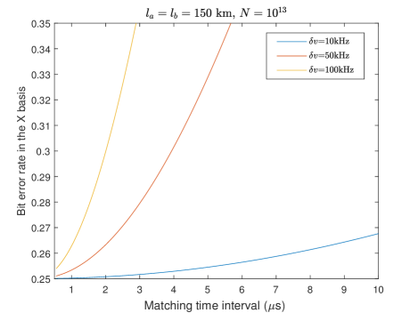
Additionally, we simulate the bit error rate in the X basis as a function of the time interval in Fig. 6, which is calculated under the optimal key rate. The distance between Alice and Bob is 300 km and the system repetition rate is GHz. The experimental parameters were set to the typical values given in Table. 2. With a fixed frequency difference, the error rate in the X basis increases as the time bin interval increases. When the frequency difference kHz, the error rate increases slowly, indicating that a relatively low system repetition rate is sufficient for the experiment.

| \addstackgap[.5] | dB/km |
IV Performance and discussion
We numerically simulate the key rate of our asynchronous-MDIQKD protocol in finite-size cases. We set the threshold . The genetic algorithm is exploited to globally search for the optimal value of light intensities and their corresponding probabilities. When optimizing the key rate, we set an additional condition in which the mean number of events . Assuming that the distribution of the number of events in follows a Poisson distribution, the probability that the observed number of events in the experiment exceeds is , where . This reveals the robustness of our protocol, which will only fail once in 100 million rounds of experiments.
The experimental parameters were set to the typical values given in Table. 2. We set the failure parameters , , , , and to be the same . We denote the distance between Alice (Bob) and Charlie as (). In the symmetric case, that is, , we have because the Chernoff bound [89, 90] is used 14 times to estimate , , and . The corresponding security bound is . Similarly, in the asymmetric case, we have and .

First, we calculate the key rates of the asynchronous-MDIQKD protocol with a short time interval . The detailed formulas for simulating our protocol are presented in Appendix B. The statistical fluctuation analysis formulas are presented in Appendix C. Fig. 7 shows a scenario in which phase tracking is removed. The time interval , and the system repetition rate is GHz. We assume that the angle of misalignment in the basis . The key rate beats the PLOB bound at 280 km under the condition where the data size is and the transmission distance reaches 450 km. One can also transmit over more than 420 km and overcome the PLOB even with a data size of .
The key rate in the case where neither phase-tracking nor phase-locking techniques are employed is shown in Fig. 8. Here, we consider the frequency differences of 3, 10 and 100 kHz. Correspondingly, the system repetition rates are 1 GHz, 4 GHz (which has been employed in the experiments in Ref. [60]) and 10 GHz. Note that when s, the phase misalignment caused by fiber phase drift is considered. The simulation results show that the proposed protocol can overcome the PLOB bound at 270 km. For the frequency difference kHz, by applying a 10 GHz system and setting the matching time interval s, the secure transmission distance can still exceed 380 km. The corresponding loss is 62 dB. In free space, if the Micius satellite [73] is used as the intermediate station Charlie, the key distribution between two ground nodes with a distance of approximately 1000 km can be realized. At an intercity distance of 300 km, the key rate is 0.15 Mbps, which is sufficient to perform a variety of tasks, including audio and video encryption.

We remark that by circumventing the need for phase tracking, the asynchronous-MDIQKD protocol has a noteworthy advantage over TFQKD at intercity distance. Typically, the maximum counting rate of a commercially available SNSPD is approximately 2 MHz per channel. For TFQKD, using strong reference light to execute phase-tracking usually consumes a count rate of about 4 MHz per channel [50] (sometimes 40 MHz peak count rate [51]), and dedicated high-performance detectors are needed. In Ref. [51], the two-parallel-nanowire serial-connected configuration is developed to address the high count rate issue. In contrast, asynchronous-MDIQKD does not impose a strict count rate requirement on the detector, and all detector count rates are usable for quantum signals. Assuming the maximum counting rate is 5 MHz per channel, at 230 km, with a 4 GHz repetition rate, the count rate of the quantum signal will be approximately 4.4 MHz per channel, which can be used for key generation in our protocol. The key rate is 350 kbps when kHz and s. However, for TFQKD, the available count rate is only 1 MHz per channel, resulting in a key rate of approximately 20 kbps [51]. In this case, the key rate of our protocol is one order of magnitude higher than that of TFQKD.
For a large time interval , say s, the phase correlation between two time bins fades. With the same experimental complexity as TFQKD, that is, using phase locking and phase tracking, one can postmatch time bins with arbitrary time interval and achieve better performance. Here, we simulate the key rates of asynchronous-MDIQKD with arbitrary time matching and compare it with those of PMQKD (PMQKD) [40] and SNSQKD with the help of actively AOPP. We set the total number of pulses as and , the misalignment in the basis as , and the security bounds as and . The detailed formulas for simulating our protocol are presented in Appendix B.

Because our protocol is an MDI-type protocol, the density matrix of the single-photon pair component is always identical in the X and Z bases for each user, regardless of the asymmetric source parameters chosen. This makes it possible for a dynamic quantum network to add or delete new user nodes without considering the source parameters of existing users. In contrast, to guarantee that the density matrix of the two users’ joint single-photon state in the X basis is the same as that in the Z basis for SNSQKD protocols, the transmission probability and intensity of the coherent state must follow strict mathematical constraint [33, 39]. However, this constraint is difficult to realize in practice, especially in networks where users are added and deleted over time, which greatly degrades their performance. By exploiting the quantum coin concept [91, 92], a recent study provided a security proof for the SNSQKD protocol when the constraint is not satisfied [80]. When comparing the key rates, we considered that the intensity of the coherent state in AOPP does not satisfy the mathematical constraint (which is often the case in practice) with a modulation deviation of decoy state to , and the other parameters have no deviation. The key rates in symmetric channels are shown in Fig. 9. The simulation results show that the key rate of asynchronous-MDIQKD is always higher than that of PMQKD and AOPP. At 500 km, for , the secret key rate of our protocol is higher than that of PMQKD, and the transmission distance is 240 km longer than that of AOPP. For , our protocol transmits over a distance of more than 500 km. Fig. 10 shows the key rate in the asymmetric channels, where km. Notably, our protocol also performs well in asymmetric channels. At 500 km, for , the key rate of our protocol is higher than that of PMQKD, and the transmission distance is 150 km longer than that of AOPP. Similarly, when , the transmission distance of the asynchronous-MDIQKD protocol is 50 km higher.
In summary, the asynchronous-MDIQKD protocol does not require complicated phase-locking and phase-tracking techniques, and it is resistant to imperfect intensity modulation. Therefore, an intercity quantum network is possible, where users can dynamically access and freely choose to perform asynchronous-MDIQKD with short time matching or arbitrary time matching.
V conclusion
In this work, we presented an asynchronous-MDIQKD protocol through time multiplexing. We realized scaling of the key rate with asynchronous two-photon interference, thus surpassing the PLOB bound. By removing phase locking and phase tracking, our protocol greatly simplifies the hardware requirement with a small sacrifice in performance. When using the same experimental techniques as TFQKD, our protocol is secure against coherent attacks, and shows longer transmission and higher key rate than PMQKD and SNSQKD (AOPP), considering imperfect intensity modulation. Our work also suggests a practical method of overcoming the linear bound of dual-rail protocols [30] without challenging technologies. In addition, our protocol can also exploit the six-state encoding [93] due to random phase modulation. Therefore, if applying single photon sources in the basis, our protocol can be made secure up to higher error rate by establishing the non-trivial mutual information between the bit-flip and phase error patterns [93, 94], thereby achieving a higher key rate. This work exhibits remarkable superiority in intercity quantum network deployment for balancing performance and technical complexity. We believe the key contributions of this work will produce exciting opportunities for the widespread deployment of global quantum networks beyond quantum key distribution, ranging from quantum repeaters to quantum entanglement distribution.
ACKNOWLEDGMENTS
We gratefully acknowledge the support from the National Natural Science Foundation of China (No. 61801420), the Natural Science Foundation of Jiangsu Province (No. BK20211145), the Fundamental Research Funds for the Central Universities (No. 020414380182), the Key Research and Development Program of Nanjing Jiangbei New Aera (No. ZDYD20210101), the Key-Area Research and Development Program of Guangdong Province (No. 2020B0303040001), and the China Postdoctoral Science Foundation (No. 2021M691536).
Note added— During the peer review of our work, we became aware of a similar work by Zeng et al. [95], who consider a mode-pairing MDI-QKD scheme that matches the adjacent detection pulses to extract the key information. By assuming infinite decoy states, they calculated the key rate in the asymptotic regime, which can break the rate-loss bound. In this work, we use the three-intensity decoy-state method to calculate the key rate in the finite-size regime and show its ability to break the rate-loss bound.
Appendix A Simulation formulas
In this section, we calculate the parameters in Eq. (1) to estimate the secret key rate. In the following description, let be the expected value of . We denote the number of as . We denote the number and error number of events after postmatching as and , respectively. For simplicity, we abbreviate as when and .
1. . corresponds to the number of successful detection events where Alice and Bob each emit a single photon in different time bins in the basis. We define () as the number of events in which Alice (Bob) emits a single photon and Bob (Alice) emits a vacuum state in () event. The lower bounds of their expected values are and , where the yields and are the corresponding yields. These can be estimated using the decoy-state method:
| (5) | ||||
| (6) |
where represents the number of events where at least one user chooses the declare-vacuum state and refers to the corresponding probability. Thus, the lower bound of can be given by
| (7) |
where , and .
2. . represents the number of events in the basis, Alice emits a zero-photon state in the two matched time bins, and the total intensity of Bob’s pulses is . We define () as the number of detection events where the state sent by Alice collapses to the vacuum state in the () event. The lower bounds of the expected values are and , respectively. In this study, we employed the relation between the expected value , and . The lower bound of can be written as
| (8) |
3. . The phase difference between Alice and Bob is defined as and the corresponding number in the event as . In the post-matching step, two time bins are matched if they have the same phase difference , and all events can be grouped according to the phase difference . We denote the number of events with phase difference as . Similar to the time-bin MDIQKD, the expected yields of single-photon pairs in the and bases satisfy the following relation:
| (9) | ||||
Suppose the global phase difference is a randomly and uniformly distributed value. The expected number of single-photon pairs can be given by
| (10) | ||||
where the coefficient 4 on the first line of the formula corresponds to the four modes of single-photon pairs in the basis, is the gain when Alice chooses intensity , and Bob chooses intensity with phase difference and . We define as the average gain, given that Alice chooses intensity , and Bob chooses intensity . When and , there is an approximation relation .
In the discrete case, the phase difference is divided into slices for , where is an integer, where . The expected number of single-photon pairs is given by
| (11) |
where is the number of events with phase difference falling into slice . is the corresponding gain.
4. . For single-photon pairs, the expected value of the phase error rate in the basis equals the expected value of the bit error rate in the basis, and the error rate . Therefore, we first calculate the number of errors of the single-photon pairs in the basis . The upper bound of can be expressed as
| (12) |
where () is the error count when the state sent by Alice (Bob) collapses to the vacuum state in events , and corresponds to the event where the states sent by Alice and Bob both collapse to vacuum states in events . The expected error counts and can be expressed as follows:
| (13) | ||||
respectively, where is the error rate of the background noise.
In the symmetric case, , , and . In this case, we have . In the asymmetric case, and . Then, the lower bound of the observed value of can be written as
| (14) |
where is the lower bounds when using Chernoff bound to estimate the real values according to the expected values and is defined in Eq. 22. The expected value of can be given by
| (15) | ||||
The upper bound of can be obtained from . The upper bound of can be obtained by , where is the upper bound while using the Chernoff bound to estimate the observed values according to the expected values and is defined in Eq. 23.
5. . Finally, for a failure probability , the upper bound of the phase error rate can be obtained by using random sampling without replacement in Eq. (26)
| (16) |
Appendix B Simulation details
B.1 Asynchronous-MDIQKD protocol for arbitrary-time matching
Similar to the time-bin encoding MDIQKD, the valid events after postmatching in the basis can be divided into correct events , , and incorrect events , . The corresponding numbers are denoted as and , respectively, which can be written as
and
where . The overall number of events in the basis is and the bit error rate in the basis is .
In the basis, the data are composed of events , , , , and . Without loss of generality, we consider the case in which all matched events satisfy . In this case, when (1), the event is considered to be an error event when different detectors (the same detector) click at time bins and .
When Alice and Bob send intensities and with phase difference , the gain corresponding to only one detector click is
| (17) | ||||
where , , and . The overall gain can be given by , where represents the zero-order modified Bessel function of the first kind. The total number of is .
The overall error count in the basis can be given as
| (18) | ||||
where refers to the angle of misalignment in the basis.
B.2 Asynchronous-MDIQKD protocol for short-term matching
The total number of time bins per is . For each detection event, the probability that it belongs to is and the probability of belonging to is , where is the average detection probability, and is the total number of time bins neighboring the given detection event. The mean number of events is .
For simplicity, we divide the post-matching window into windows with a time length of , where . In the basis, given that Alice sends and Bob sends , the detection count in the -th window and the total detection count are and , respectively. After postmatching, the number of correct and incorrect events in the basis is
| (19) | |||
respectively, where , , , . The overall number of events in the basis is , and the bit error rate in the basis is .
In our simulation, we set . Assuming that , the detection count of events in slice follows the Poisson distribution , where is the mean value of . In the postmatching step, if is even, all events within the -th will be utilized. If is odd, there will be a redundant event to be aborted. Therefore, the mean number of events per is
| (20) | ||||
The overall error count in the basis can be given as
| (21) |
where .
Appendix C Statistical fluctuation analysis
In this Appendix, we introduce the statistical fluctuation analysis method [90] used in the simulation.
Chernoff bound. Let be the expected value of . For a given expected value , the Chernoff bound can be used to obtain the upper and lower bounds of the observed value.
| (22) |
and
| (23) |
where .
Variant of Chernoff bound. For a given observed value and failure probability , the upper and lower bounds of can be acquired by the variant of the Chernoff bound
| (24) |
and
| (25) |
Random sampling without replacement. Let be a string of binary bits of size , where the number of bits is unknown. Let be a random sample (without replacement) bit string with is picked from . Let be the probability of a bit value 1 observed in . Let be the remaining bit string, where the probability of bit value 1 observed in is . The upper bound of can be expressed as
| (26) |
where
| (27) |
with and .
References
- Bennett and Brassard [2014] C. H. Bennett and G. Brassard, Quantum cryptography: Public key distribution and coin tossing, Theor. Comput. Sci. 560, 7 (2014).
- Ekert [1991] A. K. Ekert, Quantum cryptography based on bell’s theorem, Phys. Rev. Lett. 67, 661 (1991).
- Zhao et al. [2008] Y. Zhao, C.-H. F. Fung, B. Qi, C. Chen, and H.-K. Lo, Quantum hacking: Experimental demonstration of time-shift attack against practical quantum-key-distribution systems, Phys. Rev. A 78, 042333 (2008).
- Lydersen et al. [2010] L. Lydersen, C. Wiechers, C. Wittmann, D. Elser, J. Skaar, and V. Makarov, Hacking commercial quantum cryptography systems by tailored bright illumination, Nat. Photonics 4, 686 (2010).
- Tang et al. [2013] Y.-L. Tang, H.-L. Yin, X. Ma, C.-H. F. Fung, Y. Liu, H.-L. Yong, T.-Y. Chen, C.-Z. Peng, Z.-B. Chen, and J.-W. Pan, Source attack of decoy-state quantum key distribution using phase information, Phys. Rev. A 88, 022308 (2013).
- Xu et al. [2020a] F. Xu, X. Ma, Q. Zhang, H.-K. Lo, and J.-W. Pan, Secure quantum key distribution with realistic devices, Rev. Mod. Phys. 92, 025002 (2020a).
- Pirandola et al. [2020] S. Pirandola, U. L. Andersen, L. Banchi, M. Berta, D. Bunandar, R. Colbeck, D. Englund, T. Gehring, C. Lupo, C. Ottaviani, et al., Advances in quantum cryptography, Adv. Opt. Photon. 12, 1012 (2020).
- Lo et al. [2012] H.-K. Lo, M. Curty, and B. Qi, Measurement-device-independent quantum key distribution, Phys. Rev. Lett. 108, 130503 (2012).
- Braunstein and Pirandola [2012] S. L. Braunstein and S. Pirandola, Side-channel-free quantum key distribution, Phys. Rev. Lett. 108, 130502 (2012).
- Liu et al. [2013] Y. Liu, T.-Y. Chen, L.-J. Wang, H. Liang, G.-L. Shentu, J. Wang, K. Cui, H.-L. Yin, N.-L. Liu, L. Li, X. Ma, J. S. Pelc, M. M. Fejer, C.-Z. Peng, Q. Zhang, and J.-W. Pan, Experimental measurement-device-independent quantum key distribution, Phys. Rev. Lett. 111, 130502 (2013).
- Rubenok et al. [2013] A. Rubenok, J. A. Slater, P. Chan, I. Lucio-Martinez, and W. Tittel, Real-world two-photon interference and proof-of-principle quantum key distribution immune to detector attacks, Phys. Rev. Lett. 111, 130501 (2013).
- Zhou et al. [2016] Y.-H. Zhou, Z.-W. Yu, and X.-B. Wang, Making the decoy-state measurement-device-independent quantum key distribution practically useful, Phys. Rev. A 93, 042324 (2016).
- Tang et al. [2014] Z. Tang, Z. Liao, F. Xu, B. Qi, L. Qian, and H.-K. Lo, Experimental demonstration of polarization encoding measurement-device-independent quantum key distribution, Phys. Rev. Lett. 112, 190503 (2014).
- Fu et al. [2015] Y. Fu, H.-L. Yin, T.-Y. Chen, and Z.-B. Chen, Long-distance measurement-device-independent multiparty quantum communication, Phys. Rev. Lett. 114, 090501 (2015).
- Curty et al. [2014] M. Curty, F. Xu, W. Cui, C. C. W. Lim, K. Tamaki, and H.-K. Lo, Finite-key analysis for measurement-device-independent quantum key distribution, Nat. Commun. 5, 3732 (2014).
- Yin et al. [2014] H.-L. Yin, W.-F. Cao, Y. Fu, Y.-L. Tang, Y. Liu, T.-Y. Chen, and Z.-B. Chen, Long-distance measurement-device-independent quantum key distribution with coherent-state superpositions, Opt. Lett. 39, 5451 (2014).
- Comandar et al. [2016] L. Comandar, M. Lucamarini, B. Fröhlich, J. Dynes, A. Sharpe, S.-B. Tam, Z. Yuan, R. Penty, and A. Shields, Quantum key distribution without detector vulnerabilities using optically seeded lasers, Nat. Photonics 10, 312 (2016).
- Yin et al. [2016a] H.-L. Yin, T.-Y. Chen, Z.-W. Yu, H. Liu, L.-X. You, Y.-H. Zhou, S.-J. Chen, Y. Mao, M.-Q. Huang, W.-J. Zhang, H. Chen, M. J. Li, D. Nolan, F. Zhou, X. Jiang, Z. Wang, Q. Zhang, X.-B. Wang, and J.-W. Pan, Measurement-device-independent quantum key distribution over a 404 km optical fiber, Phys. Rev. Lett. 117, 190501 (2016a).
- Semenenko et al. [2020] H. Semenenko, P. Sibson, A. Hart, M. G. Thompson, J. G. Rarity, and C. Erven, Chip-based measurement-device-independent quantum key distribution, Optica 7, 238 (2020).
- Yin et al. [2017] H.-L. Yin, W.-L. Wang, Y.-L. Tang, Q. Zhao, H. Liu, X.-X. Sun, W.-J. Zhang, H. Li, I. V. Puthoor, L.-X. You, et al., Experimental measurement-device-independent quantum digital signatures over a metropolitan network, Phys. Rev. A 95, 042338 (2017).
- Wei et al. [2020] K. Wei, W. Li, H. Tan, Y. Li, H. Min, W.-J. Zhang, H. Li, L. You, Z. Wang, X. Jiang, T.-Y. Chen, S.-K. Liao, C.-Z. Peng, F. Xu, and J.-W. Pan, High-speed measurement-device-independent quantum key distribution with integrated silicon photonics, Phys. Rev. X 10, 031030 (2020).
- Woodward et al. [2021] R. I. Woodward, Y. Lo, M. Pittaluga, M. Minder, T. Paraïso, M. Lucamarini, Z. Yuan, and A. Shields, Gigahertz measurement-device-independent quantum key distribution using directly modulated lasers, npj Quantum Inf. 7, 58 (2021).
- Wang et al. [2017] C. Wang, Z.-Q. Yin, S. Wang, W. Chen, G.-C. Guo, and Z.-F. Han, Measurement-device-independent quantum key distribution robust against environmental disturbances, Optica 4, 1016 (2017).
- Zheng et al. [2021] X. Zheng, P. Zhang, R. Ge, L. Lu, G. He, Q. Chen, F. Qu, L. Zhang, X. Cai, Y. Lu, S. Zhu, P. Wu, and X.-S. Ma, Heterogeneously integrated, superconducting silicon-photonic platform for measurement-device-independent quantum key distribution, Adv. Photonics 3, 055002 (2021).
- Tang et al. [2016] Y.-L. Tang, H.-L. Yin, Q. Zhao, H. Liu, X.-X. Sun, M.-Q. Huang, W.-J. Zhang, S.-J. Chen, L. Zhang, L.-X. You, Z. Wang, Y. Liu, C.-Y. Lu, X. Jiang, X. Ma, Q. Zhang, T.-Y. Chen, and J.-W. Pan, Measurement-device-independent quantum key distribution over untrustful metropolitan network, Phys. Rev. X 6, 011024 (2016).
- Pirandola et al. [2009] S. Pirandola, R. García-Patrón, S. L. Braunstein, and S. Lloyd, Direct and reverse secret-key capacities of a quantum channel, Phys. Rev. Lett. 102, 050503 (2009).
- Takeoka et al. [2014] M. Takeoka, S. Guha, and M. M. Wilde, Fundamental rate-loss tradeoff for optical quantum key distribution, Nat. Commun. 5, 5235 (2014).
- Pirandola et al. [2017] S. Pirandola, R. Laurenza, C. Ottaviani, and L. Banchi, Fundamental limits of repeaterless quantum communications, Nat. Commun. 8, 15043 (2017).
- Pirandola [2019] S. Pirandola, End-to-end capacities of a quantum communication network, Commun. Phys. 2, 51 (2019).
- Das et al. [2021] S. Das, S. Bäuml, M. Winczewski, and K. Horodecki, Universal limitations on quantum key distribution over a network, Phys. Rev. X 11, 041016 (2021).
- Lucamarini et al. [2018] M. Lucamarini, Z. L. Yuan, J. F. Dynes, and A. J. Shields, Overcoming the rate–distance limit of quantum key distribution without quantum repeaters, Nature 557, 400 (2018).
- Ma et al. [2018] X. Ma, P. Zeng, and H. Zhou, Phase-matching quantum key distribution, Phys. Rev. X 8, 031043 (2018).
- Wang et al. [2018] X.-B. Wang, Z.-W. Yu, and X.-L. Hu, Twin-field quantum key distribution with large misalignment error, Phys. Rev. A 98, 062323 (2018).
- Yin and Fu [2019] H.-L. Yin and Y. Fu, Measurement-device-independent twin-field quantum key distribution, Sci. Rep. 9, 3045 (2019).
- Lin and Lütkenhaus [2018] J. Lin and N. Lütkenhaus, Simple security analysis of phase-matching measurement-device-independent quantum key distribution, Phys. Rev. A 98, 042332 (2018).
- Curty et al. [2019] M. Curty, K. Azuma, and H.-K. Lo, Simple security proof of twin-field type quantum key distribution protocol, npj Quantum Inf. 5, 64 (2019).
- Cui et al. [2019] C. Cui, Z.-Q. Yin, R. Wang, W. Chen, S. Wang, G.-C. Guo, and Z.-F. Han, Twin-field quantum key distribution without phase postselection, Phys. Rev. Applied 11, 034053 (2019).
- Yin and Chen [2019a] H.-L. Yin and Z.-B. Chen, Coherent-state-based twin-field quantum key distribution, Sci. Rep. 9, 14918 (2019a).
- Hu et al. [2019] X.-L. Hu, C. Jiang, Z.-W. Yu, and X.-B. Wang, Sending-or-not-sending twin-field protocol for quantum key distribution with asymmetric source parameters, Phys. Rev. A 100, 062337 (2019).
- Zeng et al. [2020] P. Zeng, W. Wu, and X. Ma, Symmetry-protected privacy: beating the rate-distance linear bound over a noisy channel, Phys. Rev. Applied 13, 064013 (2020).
- Xie et al. [2021a] Y.-M. Xie, B.-H. Li, Y.-S. Lu, X.-Y. Cao, W.-B. Liu, H.-L. Yin, and Z.-B. Chen, Overcoming the rate–distance limit of device-independent quantum key distribution, Opt. Lett. 46, 1632 (2021a).
- Wang et al. [2020] R. Wang, Z.-Q. Yin, F.-Y. Lu, S. Wang, W. Chen, C.-M. Zhang, W. Huang, B.-J. Xu, G.-C. Guo, and Z.-F. Han, Optimized protocol for twin-field quantum key distribution, Commun. Phys. 3, 149 (2020).
- Li et al. [2021] B.-H. Li, Y.-M. Xie, Z. Li, C.-X. Weng, C.-L. Li, H.-L. Yin, and Z.-B. Chen, Long-distance twin-field quantum key distribution with entangled sources, Opt. Lett. 46, 5529 (2021).
- Maeda et al. [2019] K. Maeda, T. Sasaki, and M. Koashi, Repeaterless quantum key distribution with efficient finite-key analysis overcoming the rate-distance limit, Nat. Commun. 10, 3140 (2019).
- Yin and Chen [2019b] H.-L. Yin and Z.-B. Chen, Finite-key analysis for twin-field quantum key distribution with composable security, Sci. Rep. 9, 17113 (2019b).
- Jiang et al. [2019] C. Jiang, Z.-W. Yu, X.-L. Hu, and X.-B. Wang, Unconditional security of sending or not sending twin-field quantum key distribution with finite pulses, Phys. Rev. Applied 12, 024061 (2019).
- Currás-Lorenzo et al. [2021] G. Currás-Lorenzo, Á. Navarrete, K. Azuma, G. Kato, M. Curty, and M. Razavi, Tight finite-key security for twin-field quantum key distribution, npj Quantum Inf. 7, 22 (2021).
- Minder et al. [2019] M. Minder, M. Pittaluga, G. Roberts, M. Lucamarini, J. Dynes, Z. Yuan, and A. Shields, Experimental quantum key distribution beyond the repeaterless secret key capacity, Nat. Photonics 13, 334 (2019).
- Zhong et al. [2019] X. Zhong, J. Hu, M. Curty, L. Qian, and H.-K. Lo, Proof-of-principle experimental demonstration of twin-field type quantum key distribution, Phys. Rev. Lett. 123, 100506 (2019).
- Wang et al. [2019] S. Wang, D.-Y. He, Z.-Q. Yin, F.-Y. Lu, C.-H. Cui, W. Chen, Z. Zhou, G.-C. Guo, and Z.-F. Han, Beating the fundamental rate-distance limit in a proof-of-principle quantum key distribution system, Phys. Rev. X 9, 021046 (2019).
- Liu et al. [2019] Y. Liu, Z.-W. Yu, W. Zhang, J.-Y. Guan, J.-P. Chen, C. Zhang, X.-L. Hu, H. Li, C. Jiang, J. Lin, T.-Y. Chen, L. You, Z. Wang, X.-B. Wang, Q. Zhang, and J.-W. Pan, Experimental twin-field quantum key distribution through sending or not sending, Phys. Rev. Lett. 123, 100505 (2019).
- Fang et al. [2020] X.-T. Fang, P. Zeng, H. Liu, M. Zou, W. Wu, Y.-L. Tang, Y.-J. Sheng, Y. Xiang, W. Zhang, H. Li, Z. Wang, L. You, M.-J. Li, H. Chen, Y.-A. Chen, Q. Zhang, C.-Z. Peng, X. Ma, T.-Y. Chen, and J.-W. Pan, Implementation of quantum key distribution surpassing the linear rate-transmittance bound, Nat. Photonics 14, 422 (2020).
- Chen et al. [2020] J.-P. Chen, C. Zhang, Y. Liu, C. Jiang, W. Zhang, X.-L. Hu, J.-Y. Guan, Z.-W. Yu, H. Xu, J. Lin, M.-J. Li, H. Chen, H. Li, L. You, Z. Wang, X.-B. Wang, Q. Zhang, and J.-W. Pan, Sending-or-not-sending with independent lasers: Secure twin-field quantum key distribution over 509 km, Phys. Rev. Lett. 124, 070501 (2020).
- Liu et al. [2021a] H. Liu, C. Jiang, H.-T. Zhu, M. Zou, Z.-W. Yu, X.-L. Hu, H. Xu, S. Ma, Z. Han, J.-P. Chen, Y. Dai, S.-B. Tang, W. Zhang, H. Li, L. You, Z. Wang, Y. Hua, H. Hu, H. Zhang, F. Zhou, Q. Zhang, X.-B. Wang, T.-Y. Chen, and J.-W. Pan, Field test of twin-field quantum key distribution through sending-or-not-sending over 428 km, Phys. Rev. Lett. 126, 250502 (2021a).
- Zhong et al. [2021] X. Zhong, W. Wang, L. Qian, and H.-K. Lo, Proof-of-principle experimental demonstration of twin-field quantum key distribution over optical channels with asymmetric losses, npj Quantum Inf. 7, 8 (2021).
- Chen et al. [2021a] J.-P. Chen, C. Zhang, C. Liu, Yang Jiang, W.-J. Zhang, Z.-Y. Han, S.-Z. Ma, X.-L. Hu, Y.-H. Li, F. Liu, Hui Zhou, H.-F. Jiang, H. Chen, Teng-Yun Li, L.-X. You, Z. Wang, X.-B. Wang, Q. Zhang, and J.-W. Pan, Twin-field quantum key distribution over a 511 km optical fibre linking two distant metropolitan areas, Nat. Photonics 15, 570 (2021a).
- Clivati et al. [2022] C. Clivati, A. Meda, S. Donadello, S. Virzì, M. Genovese, F. Levi, A. Mura, M. Pittaluga, Z. Yuan, A. J. Shields, M. Lucamarini, I. P. Degiovanni, and D. Calonico, Coherent phase transfer for real-world twin-field quantum key distribution, Nat. Commun. 13, 157 (2022).
- Pittaluga et al. [2021] M. Pittaluga, M. Minder, M. Lucamarini, M. Sanzaro, R. I. Woodward, M.-J. Li, Z. Yuan, and A. J. Shields, 600-km repeater-like quantum communications with dual-band stabilization, Nat. Photonics 15, 530 (2021).
- Chen et al. [2021b] J.-P. Chen, C. Zhang, Y. Liu, C. Jiang, D.-F. Zhao, W.-J. Zhang, F.-X. Chen, H. Li, L.-X. You, Z. Wang, Y. Chen, X.-B. Wang, Q. Zhang, and J.-W. Pan, Quantum key distribution over 658 km fiber with distributed vibration sensing, arXiv preprint arXiv:2110.11671 (2021b).
- Wang et al. [2022] S. Wang, Z.-Q. Yin, D.-Y. He, W. Chen, R.-Q. Wang, P. Ye, Y. Zhou, G.-J. Fan-Yuan, F.-X. Wang, W. Chen, Y.-G. Zhu, P. V. Morozov, A. V. Divochiy, Z. Zhou, G.-C. Guo, and Z.-F. Han, Twin-field quantum key distribution over 830-km fibre, Nat. Photonics 16, 154 (2022).
- Kazovsky [1986] L. Kazovsky, Balanced phase-locked loops for optical homodyne receivers: performance analysis, design considerations, and laser linewidth requirements, J. Light. Technol. 4, 182 (1986).
- Kazovsky and Atlas [1990] L. G. Kazovsky and D. A. Atlas, A 1320-nm experimental optical phase-locked loop: performance investigation and psk homodyne experiments at 140 mb/s and 2 gb/s, J. Light. Technol. 8, 1414 (1990).
- Predehl et al. [2012] K. Predehl, G. Grosche, S. M. F. Raupach, S. Droste, O. Terra, J. Alnis, T. Legero, T. W. Hänsch, T. Udem, R. Holzwarth, and H. Schnatz, A 920-kilometer optical fiber link for frequency metrology at the 19th decimal place, Science 336, 441 (2012).
- Huang et al. [2019] A. Huang, A. Navarrete, S.-H. Sun, P. Chaiwongkhot, M. Curty, and V. Makarov, Laser-seeding attack in quantum key distribution, Phys. Rev. Applied 12, 064043 (2019).
- Pang et al. [2020] X.-L. Pang, A.-L. Yang, C.-N. Zhang, J.-P. Dou, H. Li, J. Gao, and X.-M. Jin, Hacking quantum key distribution via injection locking, Phys. Rev. Applied 13, 034008 (2020).
- Lucamarini et al. [2015] M. Lucamarini, I. Choi, M. B. Ward, J. F. Dynes, Z. L. Yuan, and A. J. Shields, Practical security bounds against the trojan-horse attack in quantum key distribution, Phys. Rev. X 5, 031030 (2015).
- Sajeed et al. [2016] S. Sajeed, A. Huang, S. Sun, F. Xu, V. Makarov, and M. Curty, Insecurity of detector-device-independent quantum key distribution, Phys. Rev. Lett. 117, 250505 (2016).
- Zhang et al. [2021] G. Zhang, I. W. Primaatmaja, J. Y. Haw, X. Gong, C. Wang, and C. C. W. Lim, Securing practical quantum communication systems with optical power limiters, PRX Quantum 2, 030304 (2021).
- Bozzio et al. [2021] M. Bozzio, A. Cavaillès, E. Diamanti, A. Kent, and D. Pitalúa-García, Multiphoton and side-channel attacks in mistrustful quantum cryptography, PRX Quantum 2, 030338 (2021).
- Cao et al. [2020] Y. Cao, Y.-H. Li, K.-X. Yang, Y.-F. Jiang, S.-L. Li, X.-L. Hu, M. Abulizi, C.-L. Li, W. Zhang, Q.-C. Sun, W.-Y. Liu, X. Jiang, S.-K. Liao, J.-G. Ren, H. Li, L. You, Z. Wang, J. Yin, C.-Y. Lu, X.-B. Wang, Q. Zhang, C.-Z. Peng, and J.-W. Pan, Long-distance free-space measurement-device-independent quantum key distribution, Phys. Rev. Lett. 125, 260503 (2020).
- Liu et al. [2021b] H.-Y. Liu, X.-H. Tian, C. Gu, P. Fan, X. Ni, R. Yang, J.-N. Zhang, M. Hu, J. Guo, X. Cao, X. Hu, G. Zhao, Y.-Q. Lu, Y.-X. Gong, Z. Xie, and S.-N. Zhu, Optical-relayed entanglement distribution using drones as mobile nodes, Phys. Rev. Lett. 126, 020503 (2021b).
- Hu et al. [2021] C.-Q. Hu, Z.-Q. Yan, J. Gao, Z.-M. Li, H. Zhou, J.-P. Dou, and X.-M. Jin, Decoy-state quantum key distribution over a long-distance high-loss air-water channel, Phys. Rev. Applied 15, 024060 (2021).
- Chen et al. [2021c] Y.-A. Chen, Q. Zhang, T.-Y. Chen, W.-Q. Cai, S.-K. Liao, J. K. Chen, J. Yin, J.-G. Ren, Z. Chen, S.-L. Han, Q. Yu, K. Liang, F. Zhou, X. Yuan, M.-S. Zhao, T.-Y. Wang, X. Jiang, L. Zhang, W.-Y. Liu, Y. Li, Q. Shen, Y. Cao, C.-Y. Lu, R. Shu, J.-Y. Wang, L. Li, N.-L. Liu, F. Xu, X.-B. Wang, C.-Z. Peng, and J.-W. Pan, An integrated space-to-ground quantum communication network over 4,600 kilometres, Nature 589, 214 (2021c).
- Dequal et al. [2021] D. Dequal, L. T. Vidarte, V. R. Rodriguez, G. Vallone, P. Villoresi, A. Leverrier, and E. Diamanti, Feasibility of satellite-to-ground continuous-variable quantum key distribution, npj Quantum Inf. 7, 3 (2021).
- Yin et al. [2020a] J. Yin, Y.-H. Li, S.-K. Liao, M. Yang, Y. Cao, L. Zhang, J.-G. Ren, W.-Q. Cai, W.-Y. Liu, S.-L. Li, et al., Entanglement-based secure quantum cryptography over 1,120 kilometres, Nature 582, 501 (2020a).
- Takenaka et al. [2017] H. Takenaka, A. Carrasco-Casado, M. Fujiwara, M. Kitamura, M. Sasaki, and M. Toyoshima, Satellite-to-ground quantum-limited communication using a 50-kg-class microsatellite, Nat. Photonics 11, 502 (2017).
- Wehner et al. [2018] S. Wehner, D. Elkouss, and R. Hanson, Quantum internet: A vision for the road ahead, Science 362, eaam9288 (2018).
- Sidhu et al. [2021] J. S. Sidhu, S. K. Joshi, M. Gündoğan, T. Brougham, D. Lowndes, L. Mazzarella, M. Krutzik, S. Mohapatra, D. Dequal, G. Vallone, P. Villoresi, A. Ling, T. Jennewein, M. Mohageg, J. G. Rarity, I. Fuentes, S. Pirandola, and D. K. L. Oi, Advances in space quantum communications, IET Quantum Commun. 2, 182 (2021).
- Ma and Razavi [2012] X. Ma and M. Razavi, Alternative schemes for measurement-device-independent quantum key distribution, Phys. Rev. A 86, 062319 (2012).
- Xie et al. [2021b] Y.-M. Xie, C.-X. Weng, Y.-S. Lu, Y. Fu, Y. Wang, H.-L. Yin, and Z.-B. Chen, Scalable high-rate twin-field quantum key distribution networks without constraint of probability and intensity, arXiv preprint arXiv:2112.11165 (2021b).
- Xu et al. [2020b] H. Xu, Z.-W. Yu, C. Jiang, X.-L. Hu, and X.-B. Wang, Sending-or-not-sending twin-field quantum key distribution: Breaking the direct transmission key rate, Phys. Rev. A 101, 042330 (2020b).
- Jiang et al. [2020] C. Jiang, X.-L. Hu, H. Xu, Z.-W. Yu, and X.-B. Wang, Zigzag approach to higher key rate of sending-or-not-sending twin field quantum key distribution with finite-key effects, New J. Phys. 22, 053048 (2020).
- Azuma et al. [2015] K. Azuma, K. Tamaki, and W. J. Munro, All-photonic intercity quantum key distribution, Nat. Commun. 6, 10171 (2015).
- Bose and Home [2013] S. Bose and D. Home, Duality in entanglement enabling a test of quantum indistinguishability unaffected by interactions, Phys. Rev. Lett. 110, 140404 (2013).
- Lo et al. [2005] H.-K. Lo, X. Ma, and K. Chen, Decoy state quantum key distribution, Phys. Rev. Lett. 94, 230504 (2005).
- Wang [2005] X.-B. Wang, Beating the photon-number-splitting attack in practical quantum cryptography, Phys. Rev. Lett. 94, 230503 (2005).
- Takesue et al. [2007] H. Takesue, S. W. Nam, Q. Zhang, R. H. Hadfield, T. Honjo, K. Tamaki, and Y. Yamamoto, Quantum key distribution over a 40-db channel loss using superconducting single-photon detectors, Nat. Photonics 1, 343 (2007).
- Islam et al. [2017] N. T. Islam, C. C. W. Lim, C. Cahall, J. Kim, and D. J. Gauthier, Provably secure and high-rate quantum key distribution with time-bin qudits, Sci. Adv. 3, e1701491 (2017).
- Chernoff [1952] H. Chernoff, A measure of asymptotic efficiency for tests of a hypothesis based on the sum of observations, Ann. Math. Stat. 23, 493 (1952).
- Yin et al. [2020b] H.-L. Yin, M.-G. Zhou, J. Gu, Y.-M. Xie, Y.-S. Lu, and Z.-B. Chen, Tight security bounds for decoy-state quantum key distribution, Sci. Rep. 10, 14312 (2020b).
- Lo and Preskill [2007] H.-K. Lo and J. Preskill, Security of quantum key distribution using weak coherent states with nonrandom phases, Quantum Inf. Comput. 7, 431 (2007).
- Koashi [2009] M. Koashi, Simple security proof of quantum key distribution based on complementarity, New J. Phys. 11, 045018 (2009).
- Lo [2001] H.-K. Lo, Proof of unconditional security of six-state quatum key distribution scheme, Quantum Inf. Comput. 1, 81 (2001).
- Yin et al. [2016b] H.-L. Yin, Y. Fu, Y. Mao, and Z.-B. Chen, Security of quantum key distribution with multiphoton components, Sci. Rep. 6, 29482 (2016b).
- Zeng et al. [2022] P. Zeng, H. Zhou, W. Wu, and X. Ma, Quantum key distribution surpassing the repeaterless rate-transmittance bound without global phase locking, arXiv preprint arXiv:2201.04300 (2022).