Atomtronic protocol designs for NOON states
Abstract
The ability to reliably prepare non-classical states will play a major role in the realization of quantum technology. NOON states, belonging to the class of Schrödinger cat states, have emerged as a leading candidate for several applications. Starting from a model of dipolar bosons confined to a closed circuit of four sites, we show how to generate NOON states. This is achieved by designing protocols to transform initial Fock states to NOON states through use of time evolution, application of an external field, and local projective measurements. By variation of the external field strength, we demonstrate how the system can be controlled to encode a phase into a NOON state. We also discuss the physical feasibility, via an optical lattice setup. Our proposal illuminates the benefits of quantum integrable systems in the design of atomtronic protocols.
Quantum systems are widely considered to be the most promising foundation for the next generation of platforms in computing, communication, measurement and simulation. This is primarily due to the properties of state superposition and entanglement. To realize the potential for progress, it is necessary to establish protocols that are capable of generating important quantum states.
The NOON state is a fundamental example. It is an “all and nothing” superposition of two different modes 1, 2. For particles, it has the form
| (1) |
where the phase typically records information in applications. These include: in the fields of quantum metrology and sensing, performing precision phase-interferometry at the Heisenberg limit3 and overcoming diffraction limits in quantum lithography4; in tests of fundamental physics, NOON states are used to study Bell-type inequalities violation5; they offer promising applications in Quantum Communication and Quantum Computing6, and their utilization is expected to extend to areas such as chemistry and biology7. After an early success, using photon pairs and Hong-Ou-Mandel (HOM) interferometry8, several schemes have followed for the production and detection of photonic NOON states 2, 9, 10, 11, 12. There are also proposals using other architectures, such as circuit QED13, trapped ions 14, and Bose-Einstein condenstates15.
The atomtronic creation of Bose-atom NOON states would enable new tests, using massive states, of the foundations for quantum mechanics. One step in this direction is a proposal to demonstrate the matter-wave equivalent of the HOM effect 16. Prospects for creating Bose-atom NOON states using a double-well potential were first floated some time ago 17. This early work considered an attractive system, which is prone to instability. In principle a more robust repulsive system can be prepared to evolve to a high-fidelity approximation of a NOON state. However, the drawback there is that the process is associated with an extremely large time scale. Recently, new studies of the double-well system have been undertaken to reduce the time scale. One example proposes to adiabatically vary the system parameters through an excited-state phase transition during the process 18. Another study employs periodic driving to lower the NOON-state evolution time 19. Nonetheless, the time to generate a NOON state in these examples still, increasingly, scales with the total number of particles.
Here we present an alternative to circumvent these issues. Our approach adopts a closed-circuit of four sites, with a Fock-state input of particles in site 1, particles in site 2, and no particles in sites 3 and 4, denoted as . The initial step is to create an uber-NOON state, with the general form
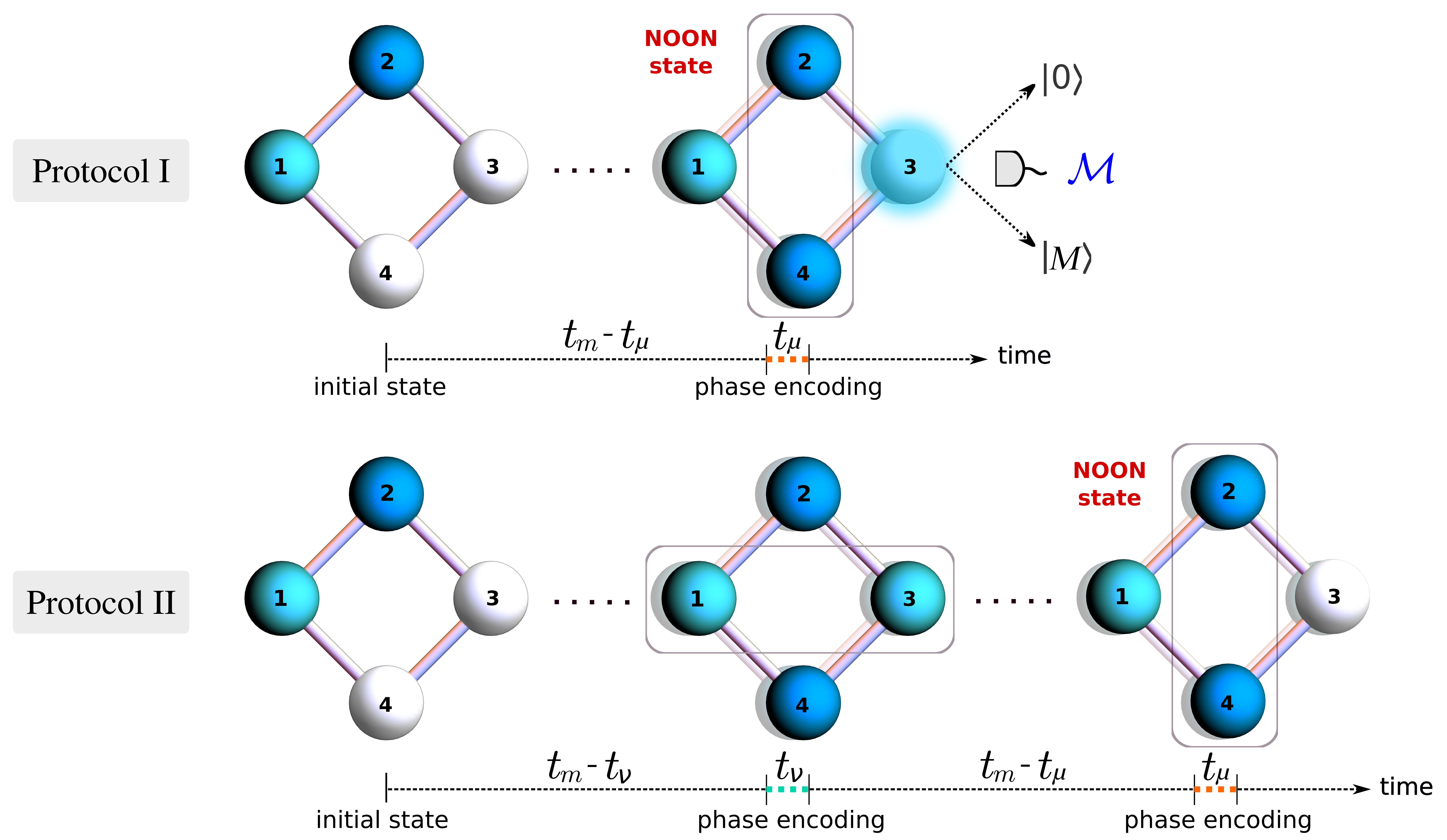
for a set of phases . This state may be viewed as an embedding of NOON states (1) within two-site subsystems. We then describe two protocols to extract a NOON state from an uber-NOON state, one through dynamical evolution followed by local projective measurement and post-selection, the other from dynamical evolution alone. The protocols are schematically presented in Fig. 1.
The approach taken has the following properties: (i) The system has long-ranged interactions, described by the Extended Bose-Hubbard Model (EBHM)20. There exists a choice of the coupling parameters for which this model is integrable21. As in other physically realized integrable systems 22, 23, 24, 25, 26, 27, 28, 29, this property facilitates several analytic calculations for physical quantities. Here, integrability exposes the protocols available for NOON state generation. The execution time is found to be dependent on the difference between the two initially populated sites within the four-site system. It is independent of total particle number, offering an encouraging prospect for scalability. (ii) The system can be controlled by breaking the integrability over small time scales. Encoding of the phase into a NOON state only requires breaking of integrability over an interval that is several orders of magnitude smaller than the entire execution time. This causes minimal loss in fidelity. (iii) With currently available technology, the system may be realized and controlled using dipolar atoms (e.g. dysprosium or erbium) trapped in an optical lattice30, 31. In this setup, the evolution times that we compute for NOON-state generation are of the order of seconds.
For the four-site configuration, the EBHM Hamiltonian is
| (2) |
where are the creation and annihilation operators for site , and are the number operators. The total number operator is conserved. Above, characterizes the interaction between bosons at the same site, is related to the long-range (e.g. dipole-dipole) interaction between bosons at sites and , and accounts for the tunneling strength between different sites.
Below, we describe two protocols that enable the generation of NOON states, with fidelities greater than 0.9. A physical setup to implement them, drawn on currently available technology, is discussed.
Results
Insights into the physical behaviour of Eq. (2) become accessible at integrable coupling. Setting , the system acquires two additional conserved quantities, and , such that and . Together with the total number of particles and the Hamiltonian , the system possesses four independent, conserved quantities. This is equal to the number of degrees of freedom, satisfying the criterion for integrability. Suppose that, initially, there are atoms in site and atoms in site . We identify the resonant tunneling regime as being achieved when (see Methods for details), where . This regime is characterized by sets of bands in the energy spectrum (see Supplementary Note 1). In this region, an effective Hamiltonian enables the derivation of analytic expressions for several physical quantities.
In the settings discussed above, the system described by Eq. (2) provides the framework to generate uber-NOON states when is odd 32. To encode phases, however, it is necessary to break the integrability in a controllable fashion. Here, we introduce two idealized protocols to produce NOON states with general phases by breaking the system’s integrability with externally applied fields. We call the subsystem containing sites as , and the one containing sites as . We denote three time intervals: , and . The first, corresponding to integrable time evolution, is associated with evolution to a particular uber-NOON state. The others, associated with smaller scale non-integrable evolution, produce phase encoding. Both protocols are built around a general time-evolution operator
where the applied field strengths , implement the breaking of integrability. It is convenient to introduce the phase variable , and to fix , with the reduced Planck constant.
Protocol I
In this protocol we employ breaking of integrability through an applied field to subsystem and a measurement process. The protocol consists of three sequential steps, schematically depicted in Fig. 1:
-
(i)
;
-
(ii)
;
-
(iii)
,
where (see Methods) and represents a projective measurement of the number of bosons at site 3 (which could be implemented, in principle, through Faraday rotation detection33, 34). A measurement outcome of 0 or heralds a high-fidelity NOON state in subsystem . For other measurement outcomes, the output is discarded and the process repeated (post-selection).
Idealized limit
There is an idealized limit for which the above protocol has perfect success probability and output fidelity. Taking , such that remains finite, and using the effective Hamiltonian, provides explicit expressions for the uber-NOON states that result at steps (i) and (ii)
| (3) |
Note that due to the conservation of and under the effective Hamiltonian, Fock states such as and do not appear in the above expression. Next, the two possible states at step (iii) depend on the measurement outcome at site 3:
| (4) |
with . These states are recognized as products of a NOON state for subsystem with Fock basis states for subsystem .
In the non-ideal case with non-zero and finite , there is a small probability that the measurement outcome is neither 0 or . Numerical benchmarks for the measurement probabilities and NOON state output fidelities are provided in a later section. Next, we describe a second protocol.
Protocol II
Now we specify an alternative protocol that does not involve measurements, so post-selection is not required. Employing the same initial state , the following sequence of steps are implemented to arrive at a NOON state in subsystem (illustrated in Fig. 1):
-
(i)
;
-
(ii)
;
-
(iii)
;
-
(iv)
.
Idealized limit
Similar to Protocol I, in the limit , , and implementing with the effective Hamiltonian produces
| (5) |
where .
Protocol fidelities
The analytic results provided above are obtained by employing the effective Hamiltonian in an extreme limit, with divergent applied fields acting for infinitesimally small times. Below we give numerical simulations of the protocols to show that, for physically realistic settings where the fields are applied for finite times, high-fidelity outcomes for NOON state production persist.
Throughout this section, we use to denote an analytic state, obtained in an idealized limit. We adopt to denote a numerically calculated state, obtained by time evolution with the EBHM Hamiltonian
(2). Two sets of parameters are chosen to illustrate the results (expressed in Hz):
Set 1: {, , };
Set 2: {, , }.
For all numerical simulation results presented below, the initial state is chosen as , i.e. and .
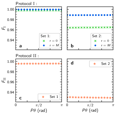
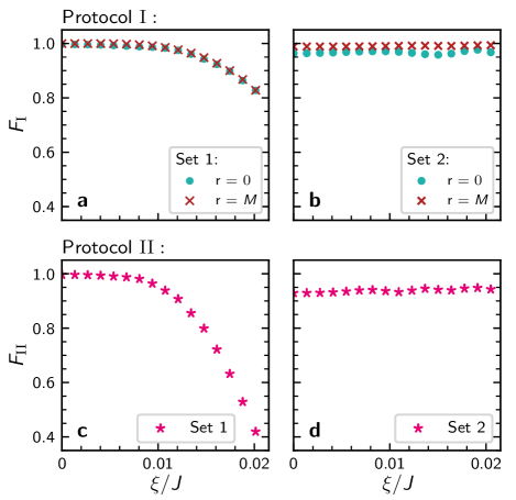
The fidelities of Protocols I and II are defined as35 and , respectively. This is computed for ranging from to , achieved by varying . In the case of Protocol II, we use for both sets of parameters. The systems considered here can, in principle, be implemented using existing hardware – see Physical proposal.
The results are presented in Fig. 2, where it is seen that is lower than . This can be attributed to two primary causes. The first is that, while Protocol I takes to produce the final state, Protocol II requires double the evolution time . The longer evolution time contributes to a loss in fidelity. The second reason is that, the measurement occurring in the final step of Protocol I has the effect of renormalizing the quantum state after collapse, which increases the fidelity of the resulting NOON state when a measurement of or is obtained. However, there is a finite probability that the measurement outcome is neither nor (see Supplementary Note 2).
In summary, both protocols display high fidelity results greater than 0.9. For Protocol I the outcomes are probabilistic (See Supplementary Note 2 for data). By contrast, the slightly lower fidelity results of Protocol II are deterministic.
Readout statistics
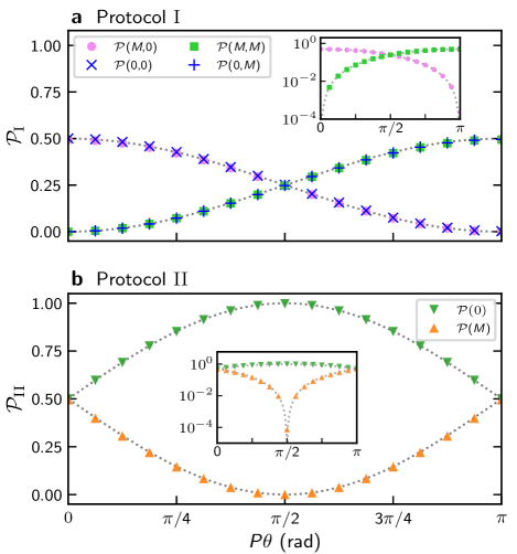
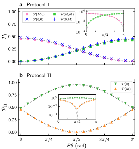
A means to test the reliability of the system, through a statistical analysis of local measurement outcomes, is directly built into the design. This results from the system’s capacity to function as an interferometer32. For both protocols, once the output state has been attained we can continue to let the system evolve under . This yields the readout states, denoted as , respectively for protocols I and II. In the idealized limits these are
where and . For , the measurement probabilities at site 3 are and . Combined with the probability of measuring in step (iii), we obtain four possibilities for the total probabilities as and . Meanwhile, for , the measurement probabilities at site 3 are and . As a numerical check, we consider the same sets of parameters from previous section. Then, we numerically calculate the above probabilities using the Hamiltonian (2), comparing the predicted analytic results with the numerical ones, as shown in Fig. 3. See Supplementary Note 2 for numerical probabilities of Protocol I, and related fidelity data. For results with Set 2, see Supplementary Note 3.
Methods
Resonant tunneling regime
The Hamiltonian (2) has large energy degeneracies when . Through numerical diagonalization of the intergable Hamiltonian for sufficiently small values of , it is seen that the levels coalesce into well-defined bands, similar to that observed in an analogous integrable three-site model37, 39. By examination of second-order tunneling processes (see Supplementary Note 1) In this regime, an effective Hamiltonian is obtained for this regime.
For an initial Fock state , with total boson number , the effective Hamiltonian is a simple function of the conserved operators with the form
| (6) |
where and . This result is valid for , and it is this inequality that we use to define the resonant tunneling regime.
A very significant feature is that, for time evolution under , both and are constant. The respective -dimensional subspace associated with sites 1 and 3 and -dimensional subspace associated with sites 2 and 4 provide the state space for the relevant energy band (see Supplementary Note 1). Restricting to these subspaces and using the effective Hamiltonian (6) yields a robust approximation for (2).
Physical proposal
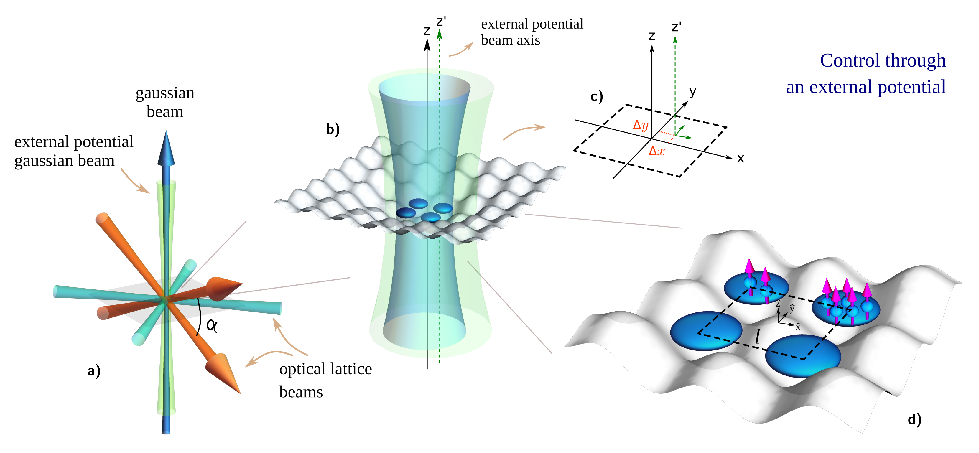
We propose a physical construction, consisting of dysprosium 164Dy atoms trapped in an optical lattice, to test the theoretical results. The trapping is accomplished by employing two sets of counterpropagating laser beams with wavelength m and waist , with . We consider each set of beams to cross with the other at an angle of (cyan beams in Fig. 5) , generating a square, two-dimensional optical lattice, in which the distance between nearest wells is nm. We also consider a Gaussian beam propagating towards the z-direction (blue beam in Fig. 5), with m and waist m, aligned to the center of a four-site square plaquette, to isolate it from the rest of the lattice. Then, to achieve a pancake-shaped trap, it is necessary to include a set of two beams with m and waist , whose orientations are disposed at an angle of from each other (orange beams in Fig. 5), inducing a trapping aspect ratio of . Together, they generate the potential :
| (7) |
where is the atom’s mass, and
are, respectively, the radial and transverse trapping frequencies. Above, arises due to the isolation of the four-well system from the optical lattice. The values and are, respectively, the central beam’s and the x-z crossing beam’s potential depths, is the 2D lattice potential depth, is the distance between nearest sites, is the wave number, and is the distance between nearest wells along the z-axis. Since we are considering , the minimum distance between the system’s horizontal layer and the next upper (or lower) layer is , which makes irrelevant the tunneling contributions between different horizontal layers.
To establish equivalency between and the Hamiltonian of Eq. (2), we employ the standard second-quantization procedure. From this, we calculate the on-site interaction parameter as:
| (8) |
where is related to the trapping (pancake) shape aspect, , , with being the s-wave scattering length (tunable via Feshbach Resonance), is the coupling constant, where is the vacuum magnetic permeability, is the atomic magnetic moment, and is a function that describes how the dipolar interaction behaves for different geometries (encoded in )38. Taking site 1 as the “starting point’, the parameter , which accounts for the dipole-dipole interaction between atoms at sites 1 and j, is expressed as:
| (9) | ||||
where is the Bessel function of first kind, , if , and , if . Here, the on-site dipolar interaction is given by . The term arises when isolating the four-site region from the rest of the lattice, which causes the wells to slightly approach each other.
Integrability condition
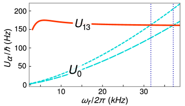
The physical setup above is able to simulate the EBHM. To achieve NOON-state generation, however, relies on the particular case for which the EBHM is integrable; as explained previously, this can be accomplished by making , which we call the “integrability condition”. The approach is to first choose a value for the s-wave scattering length via Feshbach Resonance. Then, from the condition just stated, one has to adjust by varying the laser beams intensities40 such that, at some point, becomes the same as . From this point every Hamiltonian parameter is evaluated only after the integrability condition is satisfied, which sets the intensity of the trapping scheme.
By considering () , the system becomes integrable at () kHz, as is depicted in Fig. 4. This frequency implies on a 2D-lattice depth of (), where kHz is the recoil energy, which characterizes a deep lattice. This allows for a higher stabilization of the system with a negative value for the s-wave scattering length41. Then, by using this trapping frequency to calculate the Hamiltonian parameters, one finds () Hz and () Hz. It is also important to highlight that the tunneling parameter between diagonal sites (1-3 and 2-4), which is not included in the Hamiltonian (2), is very small if compared to . From this, one infers that the tunneling between different horizontal layers of the optical lattice is even smaller, since the distance between these layers is bigger than the distance between diagonal sites by a factor of .
Breaking of integrability
To produce a controllable breaking of integrability, it is sufficient to consider a second z-oriented Gaussian beam (green beam in Fig. 5), weaker than the one used for the region isolation, with waist m and wavelength m. This beam is displaced by and (with =) from the center of the four-well system. When the laser is turned on, it implements the terms
| (10) |
where is the potential depth generated by the second beam. For m and the previously obtained radial trapping frequency, the parameters and can (non-simultaneously) assume the value of Hz. Therefore, considering and , one should vary from to s to encode from to . Also, from the condition , s.
An alternative physical setup is one designed to generate many copies of disconnected four-site plaquettes. This can be realized by overlapping two square optical lattices, each one with lattice spacing determined through different wavelengths ( and ) 42. By changing the relative phase, the breaking of integrability can be simultaneously controlled in all copies of the four-site plaquettes.
Discussion
We have offered new techniques to address the highly challenging problem of designing a framework to facilitates NOON state creation. Our approach employs dipolar atoms confined to four sites of an optical lattice. The setup allows for the interactions to be tuned, and to fix the couplings in such a way that the system is integrable. At these couplings, and for controlled perturbative breaking of the integrability, the theoretical properties of the system become very transparent.
The insights gained from integrability allowed us to develop two protocols. Protocol I employs a local measurement procedure to produce NOON states with slightly higher fidelities, over a shorter time, than Protocol II. However Protocol I is probabilistic, requiring post-selection on the measurement outcome. This is in contrast to the deterministic approach of Protocol II. For both protocols, phase-encoding is performed by breaking the system’s integrability, in a controllable fashion, at specific moments during the time evolution. And in both protocols the output states were shown to have high-fidelity in numerical simulations. We also identifed a readout scheme, by converting encoded phases into a population imbalance, that allows verification of NOON state production through measurement statistics.
The approaches we have described, that are based on the formation of an uber-NOON state en route to the final state, have two significant advantages. One is that the evolution time does not scale with the total number of particles. Instead, it is only dependent on the difference in particle number of subsystem A and B in the Fock-state input. The other advantage is that all measurements are made in the local Fock-state basis.
We conducted an analysis of the feasibility of a physical proposal. It was demonstrated that the long-range interaction between dipolar atoms allows for an integrable coupling to be achieved, depending on the interplay between contact and dipolar interactions. Through the second-quantization procedure the values for the Hamiltonian parameters were provided, derived by numerical calculations. These are seen to be realistic both in the context of optical-lattice setups and in comparison to literature. We also outlined a procedure to improve the system’s robustness with respect to error perturbation (see Supplementary Note 4 for a broader description).
Besides demonstrating the feasibility of NOON state generation, the physical setup we provide can also be employed in the study of thermalization processes and other many-body features of the EBHM. By establishing a link between integrability and quantum technologies, this work promotes advances in the field of neutral-atom quantum information processing.
Data availability
All relevant data are available on reasonable request from the authors.
References
- 1 Lee, H., Kok, P. & Dowling, J.P. A quantum Rosetta Stone for interferometry. J. Mod. Opt. 49, 2325 (2002).
- 2 Afek, I., Ambar, Oron & Silberberg, Y. High-NOON states by mixing quantum and classical light. Science 328, 879 (2010).
- 3 Bollinger, J.J., Itano, W. M., Wineland, D. J. & Heinzen, D. J. Optimal frequency measurements with maximally correlated states. Phys. Rev. A 54, R4649(R) (1996).
- 4 Boto, A. N. et al. Quantum interferometric optical lithography: exploiting entanglement to beat the diffraction limit. Phys. Rev. Lett. 85, 2733 (2000).
- 5 Wildfeuer, C. F., Lund, A. P. & Dowling, J. P. Strong violations of Bell-type inequalities for path-entangled number states. Phys. Rev. A 76, 052101 (2007).
- 6 Pan, J.-W. et al. Multiphoton entanglement and interferometry. Rev. Mod. Phys. 84, 777 (2012).
- 7 Haas, J. et al. Chem/bio sensing with non-classical light and integrated photonics. Analyst 143, 593-605 (2018).
- 8 Rarity, J. G. et al. Two-photon interference in a Mach-Zehnder interferometer. Phys. Rev. Lett. 65, 1348 (1990).
- 9 Pryde, G. J. & White, A. G. Creation of maximally entangled photon-number states using optical fiber multiports. Phys. Rev. A. 68, 052315 (2003).
- 10 Resch, K. J. et al. Time-Reversal and Super-Resolving Phase Measurements. Phys. Rev. Lett. 98, 223601 (2007).
- 11 Kamide, K., Ota, Y., Iwamoto, S. & Arakawa, Y. Method for generating a photonic NOON state with quantum dots in coupled nanocavities. Phys. Rev. A 96, 013853 (2017).
- 12 Soto-Eguibar, F. & Moya-Cessa, H.M. Generation of NOON states in waveguide arrays. Ann. Phys. 531, 1900250 (2019).
- 13 Merkel, S. T. & Wilhelm, F. K. Generation and detection of NOON states in superconducting circuits. New J. Phys. 12, 093036 (2010).
- 14 Hu, Y.M., Feng, M. & Lee, C. Adiabatic Mach-Zehnder interferometer via an array of trapped ions. Phys. Rev. A 85, 043604 (2012).
- 15 Cable, H., Laloë, F. & Mullin, W. J. Formation of NOON states from Fock-state Bose-Einstein condensates. Phys. Rev. A 83, 053626 (2011).
- 16 Lewis-Swan, R. J. & Kheruntsyan K. V. Proposal for demonstrating the Hong–Ou–Mandel effect with matter waves. Nat. Commun. 5, 3752 (2014).
- 17 Cirac, J. I., Lewenstein, M., Mölmer, K. & Zoller, P. Quantum superposition states of Bose-Einstein condensates. Phys. Rev. A 57, 1208 (1998).
- 18 Bychek, A. A., Maksimov, D. N. & Kolovsky, A. R. NOON state of Bose atoms in the double-well potential via an excited-state quantum phase transition. Phys. Rev. A 97, 063624 (2018).
- 19 Vanhaele, G. & Schlagheck, P. NOON states with ultracold bosonic atoms via resonance- and chaos-assisted tunneling. arXiv:2008.12156.
- 20 Góral, K., Santos, L. & Lewenstein, M. Quantum phases of dipolar bosons in optical lattices. Phys. Rev. Lett. 88, 170406 (2002).
- 21 Tonel, A. P., Ymai, L. H., Foerster, A. & Links, J. Integrable model of bosons in a four-well ring with anisotropic tunneling. J. Phys. A: Math. Theor. 48, 494001 (2015).
- 22 Kinoshita, T., Wenger, T. & Weiss, D. S. A quantum Newton’s cradle. Nature 440, 900-903 (2006).
- 23 Liao, Y. et al. Spin-imbalance in a one-dimensional Fermi gas. Nature 467, 567-569 (2010).
- 24 Pagano, G. et al. A one-dimensional liquid of fermions with tunable spin. Nat. Phys. 10, 198-201 (2014).
- 25 Batchelor, M. T. & Foerster, A. Yang–Baxter integrable models in experiments: from condensed matter to ultracold atoms. J. Phys. A: Math. Theor. 49, 17 (2016).
- 26 Yang, B. et al. Quantum criticality and the Tomonaga-Luttinger liquid in one-dimensional Bose gases. Phys. Rev. Lett. 119, 165701 (2017).
- 27 Breunig, O. et al. Quantum criticality in the spin-1/2 Heisenberg chain system copper pyrazine dinitrate. Science Adv. 3, 12 (2017).
- 28 Wang, Z. et al. Experimental observation of Bethe strings. Nature 554, 219-223 (2018).
- 29 Pilatowsky-Cameo, S. et al. Positive quantum Lyapunov exponents in experimental systems with a regular classical limit. Phys. Rev. E 101 010202(R) (2020).
- 30 Yao, N.Y. et al. Bilayer fractional quantum Hall states with ultracold dysprosium. Phys. Rev. A 92, 033609 (2015).
- 31 Baier, S. et al. Extended Bose-Hubbard models with ultracold magnetic atoms. Science 352, 6282 (2016).
- 32 Grün, D. S., Wittmann W. K., Ymai, L. H., Tonel, A. P., Foerster, A. & Links, J. Integrable atomtronic interferometry. arXiv:2004.11987.
- 33 Yamamoto, R. et al. Site-resolved imaging of single atoms with a Faraday quantum gas microscope. Phys. Rev. A 96, 033610 (2017).
- 34 Schäfer, F., Fukuhara, T., Sugawa, S., Takasu, Y. & Takahashi, Y. Tools for quantum simulation with ultracold atoms in optical lattices. Nat. Rev. Phys. 2, 411-425 (2020).
- 35 Nielsen, M. A. & Chuang, I. L. Quantum Computation and Quantum Information. (Cambridge Univ. Press, 2010).
- 36 Gibbons, M. J., Kim, S. Y., Fortier, K. M., Ahmadi, P., & Chapman, M. S. Achieving very long lifetimes in optical lattices with pulsed cooling. Phys. Rev. A 78, 043418 (2008).
- 37 Wilsmann, K. W., Ymai, L. H., Tonel, A. P., Links, J. & Foerster, A. Control of tunneling in an atomtronic switching device. Comm. Phys. 1, 91 (2018).
- 38 Lahaye, T., Menotti, C., Santos, L., Lewenstein, M. & Pfau, T. The physics of dipolar bosonic quantum gases. Rep. Prog. Phys. 72, 126401 (2009).
- 39 Tonel, A.P., Ymai, L. H., Wilsmann, K. W., Foerster, A. & Links, J. Entangled states of dipolar bosons generated in a triple-well potential. SciPost Phys. Core 2, 003 (2020).
- 40 Bloch, I. Ultracold quantum gases in optical lattices. Nat. Phys. 1, 23-30 (2005).
- 41 Müller, S. et al. Stability of a dipolar Bose-Einstein condensate in a one-dimensional lattice. Phys. Rev. A 84, 053601 (2011).
- 42 Dai, H.-N. et a. Four-body ring-exchange interactions and anyonic statistics within a minimal toric-code Hamiltonian. Nat. Phys. 13, 1195 (2017).
Acknowledgements
D.S.G. and K.W.W. were supported by CNPq (Conselho Nacional de Desenvolvimento Científico e Tecnológico), Brazil. A.F. acknowledges support from CNPq - Edital Universal 430827/2016-4. A.F. and J.L. received funding from the Australian Research Council through Discovery Project DP200101339. J.L. acknowledges the traditional owners of the land on which The University of Queensland operates, the Turrbal and Jagera people. We thank Ricardo R. B. Correia and Bing Yang for helpful discussions.
Author contributions
All authors contributed to the conceptualization of the project, and actively engaged in the writing of the manuscript. D.S.G, K.W.W. and L.H.Y. implemented the theoretical analyses of the model, detailed the physical proposal, and processed the numerical computations. J.L. and A.F. designed the research framework, and directed the program of activities.
Supplementary Note 1: Energy bands and effective Hamiltonian
Here we give an overview of the origin for the effective Hamiltonian. Recall that the integrability condition is and . When , the Fock state is eigenstate of the Hamiltonian (2) with energy
| (S.1) |
where . The result is
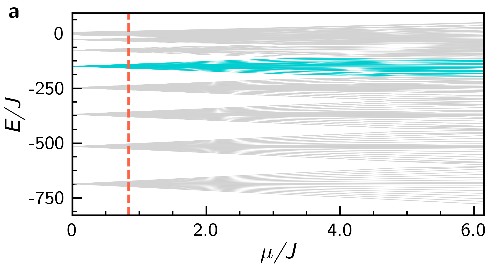
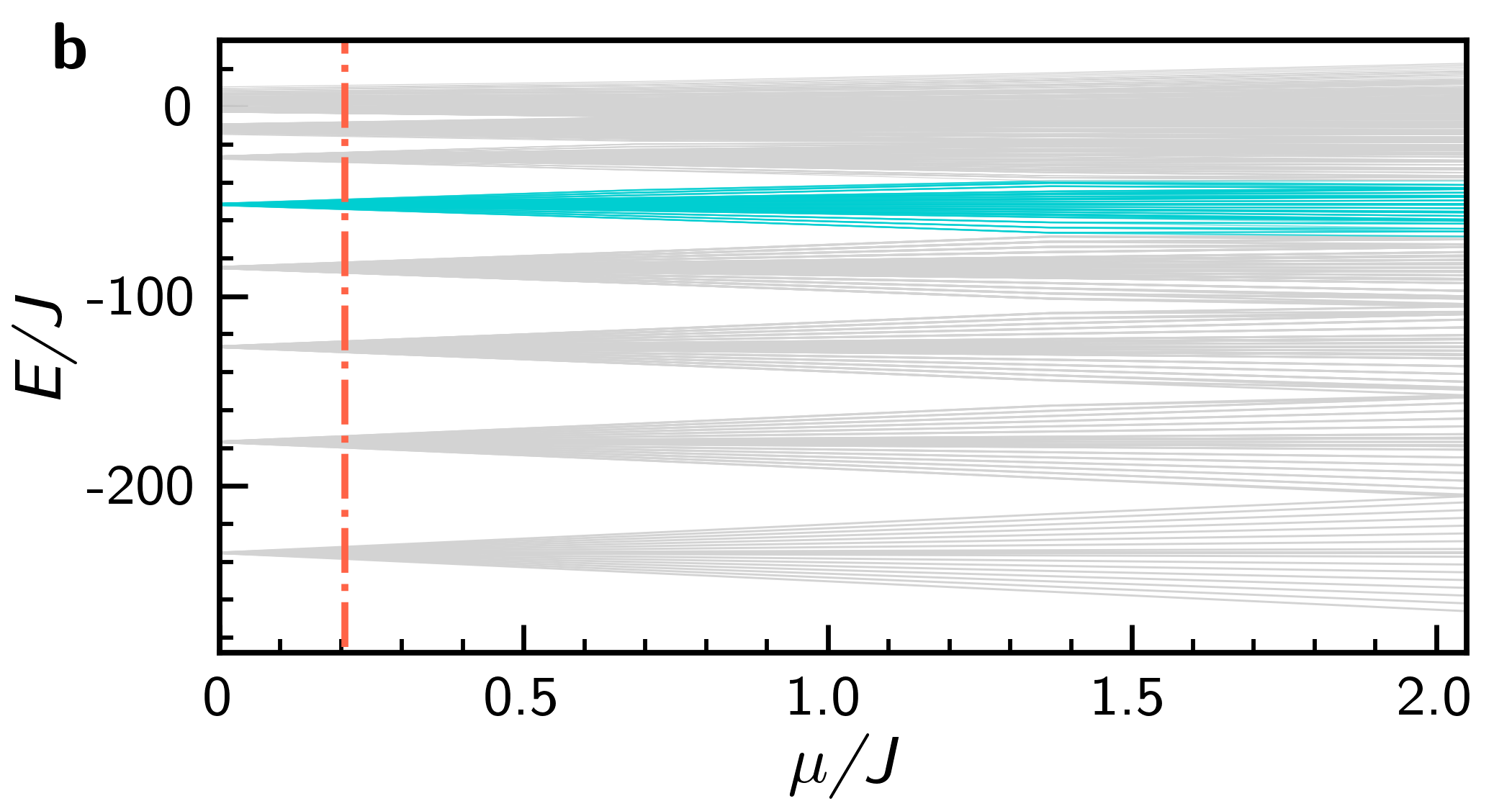
independent of and , indicating degeneracies. For small values of , the degeneracies are broken and lead to energy levels in well-defined bands, each with energy levels, except for even, where the band with the highest energy, , will have levels. The level energy structure of the case we are analyzing, with , is shown in Supplementary Figure 1. In it, we highlight in cyan the band with and (and vice versa), while the vertical lines marks the two sets of parameters pointed in the main text (repeated here, expressed in Hz):
Set 1: {, , };
Set 2: {, , }.
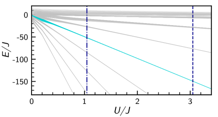
An effective Hamiltonian for each band is obtained by consideration of second-order processes. Associated to labels and , such that , we obtain
For a given initial Fock state, the resonant regime is achieved when the expectation energy lies in a region characterized by an energy band. There, the values of the integrability-breaking parameters , may be as large as the band-separation allows, which is depicted in Supplementary Figure 2.
Supplementary Note 2: Probabilities and fidelities
Supplementary Table 1 shows the measurement probabilities of Protocol I, as well as the fidelity of the resulting state with the respective NOON state, for , and the two aforementioned sets of parameters. The resulting NOON state from Protocol I can be either symmetric () or antisymmetric (). For intermediate values for the outcome of measuring , we calculate the fidelity of the resulting state with the symmetric NOON state () or the antisymmetric state (), respectively.
Protocol I:
| Set 1 | ||||||||||||
| Phase () | ||||||||||||
| Measurement | ||||||||||||
| 0 | 0.5009 | 0.9977 | 0.5009 | 0.9977 | 0.5009 | 0.9978 | 0.5009 | 0.9978 | 0.5009 | 0.9977 | 0.5009 | 0.9978 |
| 1 | 0.0006 | 0.0488 | 0.0006 | 0.0489 | 0.0006 | 0.0494 | 0.0006 | 0.0499 | 0.0006 | 0.0501 | 0.0006 | 0.0512 |
| 2 | 0.0003 | 0.0164 | 0.0003 | 0.0160 | 0.0003 | 0.0155 | 0.0003 | 0.0162 | 0.0003 | 0.0169 | 0.0003 | 0.0155 |
| 3 | 0.0013 | 0.0447 | 0.0013 | 0.0450 | 0.0013 | 0.0452 | 0.0013 | 0.0453 | 0.0013 | 0.0454 | 0.0013 | 0.0463 |
| M=4 | 0.4956 | 0.9996 | 0.4957 | 0.9996 | 0.4956 | 0.9996 | 0.4956 | 0.9996 | 0.4957 | 0.9996 | 0.4957 | 0.9996 |
| Set 2 | ||||||||||||
| Phase () | ||||||||||||
| Measurement | ||||||||||||
| 0 | 0.4922 | 0.9642 | 0.4922 | 0.9643 | 0.4922 | 0.9644 | 0.4922 | 0.9644 | 0.4922 | 0.9645 | 0.4923 | 0.9649 |
| 1 | 0.0097 | 0.1219 | 0.0097 | 0.1221 | 0.0097 | 0.1219 | 0.0097 | 0.1214 | 0.0097 | 0.1221 | 0.0096 | 0.1214 |
| 2 | 0.0053 | 0.0400 | 0.0053 | 0.0384 | 0.0053 | 0.0378 | 0.0053 | 0.0375 | 0.0053 | 0.0363 | 0.0053 | 0.0320 |
| 3 | 0.0139 | 0.1336 | 0.0139 | 0.1338 | 0.0139 | 0.1333 | 0.0139 | 0.1332 | 0.0139 | 0.1332 | 0.0139 | 0.1325 |
| M=4 | 0.4629 | 0.9886 | 0.4631 | 0.9886 | 0.4632 | 0.9887 | 0.4633 | 0.9887 | 0.4635 | 0.9887 | 0.4640 | 0.9888 |
Supplementary Note 3: Readout statistics
For less ideal choices of parameters, it is possible to perform a fitting on the readout probabilities amplitudes, such that
where , , and are constants that are obtained by fitting the numerically-evaluated data with the analytic models. By choosing the parameters of Set 2, we obtain the following constants from a least-squares fitting: , , and . The results are shown in Supplementary Figure 3.
Supplementary Note 4: Robustness
Here we analyze the system’s robustness in the presence of a perturbation parameter, and outline a method to enhance performance. Supposing that the integrability condition is subject to an error, denoted by :
| (S.2) |
We find that the fidelities for the parameters Set 1 are above 0.9 for an error parameter up to , while the parameter Set 2 is able to produce NOON state with fidelities above up to .
To enhance the fidelity, we propose a procedure that consists of both positive () and negative () deviations in Eq. (S.2). This can be done, for instance, by considering a sequence of pulses1. This is appropriate when considering an error parameter in the physical setup: after fixing the desired (approximate) s-wave scattering length, the trapping frequency adjustment may not have the required precision, allowing for a minimum-error of .
Considering perturbations of the Hamiltonian, with the form
set , and as the mean values for the two cases and . We then calculate the times and from these mean values. Next, running a simulation that alternates times between the extreme coupling values during the integrable time evolution over leads to an increase in the system’s tolerance to the error, as depicted in Supplementary Figure 4.
.
Supplementary Reference
- 1 Zhou, X., Jin, S. & Schmiedmayer, J. Shortcut loading a Bose–Einstein condensate into an optical lattice. New J. Phys. 20, 055005 (2018).