A Projection Method for Compressible Generic Two-Fluid Model
Abstract
A new projection method for a generic two-fluid model is presented in this work. To be specific, it is shown that the projection method for solving single-phase variable density incompressible flows or compressible flows can be extended to the case of viscous compressible two-fluid flows. The idea relies on the property that the single pressure can be uniquely determined by the products of volume fractions and densities of the two fluids, respectively. Moreover, a suitable assignment of the intermediate step variables is necessary to maintain the stability. The energy stability for the proposed numerical scheme is proved and the first order convergence in time is justified by three numerical tests.
1 Introduction
Multi-fluid flows are widely seen in both nature and industry. For instance, the oil/gas/water three-phase system is encountered in petroleum industry[1, 2, 3]; two-gas system is used in the semiconductor manufacture[4, 5, 6]; and gas/liquid system occurs in many chemical engineering processes[7, 8, 9, 10]. The simplest case is the two-fluid system. In this case, each fluid obey its own governing equations and interact with the other fluid through the free surface or some constitutive relations.
Several versions of the model for two-fluid flows have been proposed. They can be roughly divided into two classes: (i) Interface-capturing models [11, 12, 13, 14] and (ii) Averaged models [15, 16, 17, 18, 19]. The use of interface-capturing models is able to resolve the topology of phase distribution and extract the physical detail in the system. When the topology of the phase distribution is too complicated or the interface between phases involves large variety of length scales, the class of averaged models can be a good compromise for simulating the flow problem. Although the information of the interface is blurred by the use of averaged model, several advantages arise instead: (i) a cheaper computational cost; (ii) less sensitive to mesh than interfacial-capturing model; and (iii) simpler expression of the interfacial terms.
In this work, a generic two-fluid model with similar form as [15] is considered. The unknown variables of the system are two velocities, two densities, two volume fractions, and one pressure. It is worth noting that such model allows a disparity of motion between the two phases, which is quite common in gas-liquid system. As far as the author’s knowledge, there is no mathematically provable stable numerical scheme for solving this system. To begin with the development, some ideas are borrowed by the numerical method for single phase variable density incompressible Navier-Stokes equations[20] and for single phase compressible Navier-Stokes equations[21, 22]. Both of them are of the framework of projection method [23, 24, 25]. Several difficulties occur when extending their ideas to the two-fluid system. The main issues are the following two: (i) One will have to solve one pressure by the two intermediate velocities in the projection step. The asymmetric structure causes that the pressure cannot be obtained by means of the formulation proposed in [21] directly; (ii) A proper assignment of the intermediate volume fractions and densities to advection-diffusion step and renormalization step shall be taken care to maintain the stability.
A prediction-correction procedure in the framework of projection method for the two-fluid model being considered is proposed. To tackle the asymmetric structure in the projection step, we may observe that the pressure can be uniquely determined by the products of volume fraction and density (say and ) of the two phases (see [15] or Section 2.2 in this paper). A symmetric formulation proposed in this paper for solving and together provides an available way to accomplish the projection step. For the other main issue, the choice of intermediate step of volume fractions and densities can be understood by the process of the stability analysis.
The method for analyzing the stability of the method is similar to [26, 20]. However, there are some difficulties for keeping the energy bounds of potential functions. To this end, auxiliary functions related to the equation of states are introduced to complete the proof of the energy estimates. Finally, it is shown that the proposed time-discrete scheme is unconditionally stable.
The paper is organized as follows. In Section 2, the governing equations and their reformulation being considered are presented. Some relations among the unknown variables are introduced. The a priori estimates for clarifying the motivation of the numerical scheme are exhibited. In Section 3, the time-discrete projection method for the considered two-fluid model is provided and the finite element implementation for numerical tests is introduced. In Section 4, the stability analysis for time-discrete scheme is conducted. In Section 5, three test problems implemented by finite element method with convergence test justify the feasibility of the numerical scheme.
2 Modeling equations
In the following, we assume that the fluid domain , is smooth, bounded and connected. Let be the final time. We denote by its boundary. For convenience, we define and .
2.1 Compressible generic two-fluid model
We denote by the subscript for phase and phase , respectively. Let be the volume fractions, be the densities, be the velocities, be the pressures. The governing equations are given by
| (2.1a) | |||
| (2.1b) | |||
| (2.1c) | |||
| (2.1d) | |||
| The constraint (2.1d) is to close the system so that the number of variables equals to the number of equations. | |||
The stress tensor are of the form
| (2.2) |
where denotes the symmetric part of the velocity gradient , are the dynamic viscosities and are the second viscosities. The drag force are assumed to be of the form:
| (2.3) |
where is assumed to be a positive constant.
Equation of state
We assume the barotropic system such that
| (2.4) |
with
| (2.5) |
for some positive constants . In this work, we further assume that for .
Boundary conditions and Initial conditions
To complete the statement of the mathematical problem, we impose that
| (2.6) | |||
where is the inlet boundary such that
| (2.7) |
where is the outer normal on .
2.2 Reformulation of the governing equations
Let , (2.1) becomes
| (2.8a) | ||||
| (2.8b) | ||||
| (2.8c) | ||||
In the following, we will show that with given and , the quantities , , , , and can be uniquely determined.
Pressure balance
By (2.1d), we have
| (2.9) |
By , we have
Using (2.9), the differential of the gaseous phase volume fraction can be expressed as
Note that we always work with the case with . The differential of the gaseous phase density can be expressed as
Therefore, the differential of pressure can be expressed as
| (2.10) |
where
| (2.11) |
With (2.10) in hand, (2.8c) can be rewritten as
| (2.12) |
Relations among , , and
We recall (2.8a), which gives us
| (2.13) |
By the pressure equilibrium assumption (2.1d), we have
| (2.14) |
Differentiating with respect to yields
Therefore is a non-decreasing function of . For non-degenerate case , we look for . Since , is uniquely determined by solving with given and . Finally, and , are given by
| (2.15) |
2.3 A priori estimates to (2.8a)-(2.8c)
In this work, the stability issues are particularly payed attention and a discrete version associated to the numerical scheme is desired. Let us recall the a priori estimates associated to problem (2.8a)-(2.8c) with zero forcing term and zero velocities on for all time[15]. The following estimates present the positiveness of the mass, mass conservation, and the energy stability, respectively. For , we have
-
•
Positiveness of the mass
(2.16) -
•
Mass conservation
(2.17) -
•
Energy stability
(2.18)
In the above, is the potential energy dervied from the equation of state such that
| (2.19) |
We may choose proper constants so that the following expression makes sense:
| (2.20) |
3 Numerical scheme
3.1 Time-discrete scheme
We proceed the following to get the time-discrete solution:
-
•
Step 1. Prediction of the mass fraction :
(3.1) -
•
Step 2. Solve the intermediate volume fraction and the density by
(3.2) -
•
Step 3. Renormalization of the intermediate pressure :
(3.3) with the boundary constraint:
(3.4) -
•
Step 4. Solve the intermediate velocities
(3.5) -
•
Step 5. (Projection) Solve , , , :
(3.6) with the boundary constraint
(3.7) -
•
Step 6. Renormalization of the end-of-step velocities :
(3.8)
Equivalent problem of the projection step
To eliminate the variable in the coupling problem (3.6), we may manipulate the first two equations in (3.6) to get
-
•
Step 5’. Solve , , :
(3.9)
In view of the asymmetric structure of (3.9), it is not easy to solve the problem directly. To tackle the difficulty, the argument in Section 2.2 is applied so that we can express in terms of and . A symmetric projection step can be expressed as
-
•
Step 5”. Solve , :
(3.10)
Remark 1
Step 5” is solved iteratively in this way: Given , at the -th iteration step, the solutions for the -th iteration step are given by
| (3.11) |
3.2 Finite element implementation
For simplicity, we consider the problem with on , . The case with nonhomogeneous boundary conditions or outlet can be modified accordingly by a standard way.
Let us introduce finite element approximations for densities (also for intermediate step ), volume fractions (also for intermediate step ), their products (also for intermediate step ), and for pressure (also for intermediate step ); for intermediate step velocities .
To maintain the positiveness of , the weak formulation for Step 1 - (3.1) reads: For , find such that for and such that for all with ,
| (3.12) |
The positiveness of the above scheme is shown in Remark 2.
At Step 2, the intermediate and can be obtain pointwisely by the given without error generation by spatial discretization since all of them belong to the same space . One may conduct a root-finding technique (e.g. Ridder’s method[27]) to solve and pointwisely.
The renormalization (Step 3) for intermediate pressure can be proceeded by the following problem: For , find such that for all ,
| (3.13) |
We note that the boundary terms are eliminated because of (3.4).
The weak formulation for Step 4 (advection-diffusion step) reads: For , find such that for all ,
| (3.14) | ||||
The above equation can be solved separately for and and the nonlinear term can be tackled by iteration (see for example [28]).
The projection step (Step 5) is handled by (3.10) and the according weak formulation reads: For , find such that for all ,
| (3.15) |
with
| (3.16) |
The above system can be solved iteratively by the way provided in Remark 1. In (3.16), functions of and : , , and are taken to be their projection on . Similar to (3.13), the boundary terms of (3.15) are eliminated because of the boundary constraint (3.7).
4 Stability analysis
Let be any function. We denote by and by . We denote by the norm on , the norm, and , , . We denote by the inner product associated to space such that for in .
Mass conservation
Step 5 and Step 6 guarantee the mass conservation in the following sense:
Energy estimates of (3.1)-(3.8)
We recall an important lemma which will be used several times:
Lemma 1
For sufficiently smooth and with , we have
Let us start with the estimates for the intermediate pressures . Taking the inner product of (3.3) with ,
Therefore,
| (4.2) |
Summing the inner product of (3.5) with and the inner product of (3.1) with , we have
| (4.3) | ||||
where . Using the Cauchy’s inequality, Green’s theorem, and an analogue of Lemma 1, we have
| (4.4) |
Taking the inner product of the first equation in (3.6) with ,
| (4.5) | |||
Taking the inner product of the first equation in (3.6) again with ,
| (4.6) | ||||
Combining (4.2)-(4.6), we have
| (4.7) | |||
Using the first equation in (3.6), we have
| (4.8) | ||||
To this stage, the problem is to estimate . Let us introduce auxiliary functions . If , then are , strictly convex functions for . Indeed, we have the following by definition:
Differentiating twice with respect to , we get
Therefore, we have
| (4.9) |
We observe that
| (4.10) | ||||
On the other hand
| (4.11) | ||||
Now,
| (4.12) | ||||
Since and , we have
| (4.13) |
Now, we have
| (4.14) |
Taking the summation with respect to , we have
| (4.15) | ||||
Using (4.8), (4.15), and (3.8), we have
| (4.16) | ||||
Summing over , we arrive at the theorem:
Theorem 1
Remark 2
The prediction step (3.1) does not guarantee the positiveness of . An modification is possible to force its positiveness:
| (4.18) |
Indeed, taking the inner product of (4.18) with , we have
Using Lemma 1, the second term on the left hand side can be eliminated. Therefore, we have almost everywhere provided almost everywhere. This implies the positiveness of .
5 Numerical test
Let be the reference length scale, be the reference velocity, and be the reference density. The parameters and variables in use are scaled by the following:
In the following test, we assume that for simplicity.
For Sections 5.1 and 5.2, we consider a square physical domain of size . The initial values are constructed by the following procedure:
-
1.
Set the initial of volume fractions and densities: , .
-
2.
Let .
-
3.
Set the initial values of intermediate step: , .
-
4.
Solve a steady state Stokes equation with admissible boundary conditions for initial velocities and pressure: Find such that
(5.1) where . We set , .
In the following context, the P1-bubble element (see for instance [29]) is applied for velocities field and element is applied for all other variables. The computer program for the implementation is written using Freefem++ [30].
5.1 Two-gas system
First, the case that the two fluids possess similar densities is taken into account. The parameters in use are listed in Table 1. The initial values for volume fractions and densities are
| (5.2) | ||||
The initial velocities are obtained by solving (5.1) with and .
For all test, a uniform triangular mesh is employed and we compare the test results with the numerical solution with at the final time . The convergence test shows a first order accuracy in time for all variables (see Figure 1).
We note that in this case, the densities of both phases change only slightly (less than times of their original densities). Therefore, it is safe for us to discuss only the volume fractions or their products with the densities .
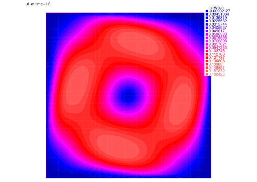
the contours in Figure 2 show that the two phases tend to separate at the beginning. That is, the spinning velocity field (see Figure 3) reduces the volume fraction of the lighter phase in its region of lower volume fraction, and vice versa. Indeed, the difference between the velocities of the two fluids is observed: According to 3, the lower density material is accelerated. A possible explanation is the virtual force caused by the density difference. On the other hand, the material of higher density is decelerated in view of 4. This result is natural because of the dissipation by viscous force and the momentum transfer by the drag force from phase to phase .
| Parameters | Values | Parameters | Values |
|---|---|---|---|


5.2 Liquid-gas system
With the same domain as in Section 5.1, the parameters in use are listed in Table 2. We assume the same initial volume fractions as the test in Section 5.1 but different initial densities:
| (5.3) | ||||
The initial velocities are obtained by solving (5.1) with and .
For all test, a uniform triangular mesh is employed and we compare the test results with the numerical solution with at the final time . The convergence in this case is worse than the test of two-gas system. Fortunately, a first order convergence is still kept (see Figure 5).
Similar to the test of two-gas system, the densities of both phases change only slightly (less than times of their original densities). According to Figure 6 a separation phenomenon can be observed in this case as well due to the difference between velocities of the two fluids. The acceleration for lower density phase and the deceleration for higher density phase can be seen from Figures 7 and 8. With finite element implementation for the case of large density difference, undesired oscillation tends to spread rapidly if the time step is not chosen sufficiently small. A smaller time step than that of the test for two-gas system is therefore adopted here.
| Parameters | Values | Parameters | Values |
|---|---|---|---|


5.3 Liquid-gas system with initially large pressure gradient
In this case, we consider the same physical domain as what is used in Sections 5.1 and 5.2 and the parameters presented in Table 2. The initial values of the volume fractions are
| (5.4) |
The initial pressure distribution is given by
| (5.5) |
The initial densities are determined accordingly:
| (5.6) |
The initial velocities are given by
| (5.7) |
and the homogeneous boundary conditions for velocities are imposed:
| (5.8) |
For all test, a uniform triangular mesh is employed and we compare the test results with the numerical solution with at the final time . A much smaller time step is chosen in order to capture the rapid change of the density field of phase (see Figure 12). The convergence results given by Figure 9 present a first order accuracy in this case.
The magnitude contours of and given by Figures 10 and 11 do not show a large change with time. However, their quotient change rapidly so that a very small time step is needed to capture its wave-motion. This example implies that the wave velocity of the propagation may be of different scale with the wave velocity of the density change.
In the scenario of this test, the main driven force for the fluid velocities is the pressure. Since the pressure force for each phase is proportional to its volume fraction, the acceleration by the pressure force is reciprocal to the density. Indeed, Figures 13 and 14 present a large different between velocities of the two fluids.


6 Conclusion
In this work, a new projection method for solving a viscous two-fluid model is proposed. A symmetric formulation of the projection step enables the computation of the projected pressure. Moreover a suitable assignment of the intermediate densities and volume fractions maintain the stability of the numerical scheme, which is justify by the stability analysis for the time-discrete problem. Numerical tests show that the method can not only be recovered to treat the problem with fluids being slightly compressed but also be used for the case with heavily compressed fluids. A first order temporal accuracy of the scheme is justified by all numerical tests in Section 5.
References
- [1] R. Thorn, G. A. Johansen, and B. T. Hjertaker, “Three-phase flow measurement in the petroleum industry,” Measurement Science and Technology, vol. 24, no. 1, p. 012003, 2012.
- [2] C. Jabbour, M. Quintard, H. Bertin, and M. Robin, “Oil recovery by steam injection: three-phase flow effects,” Journal of Petroleum Science and Engineering, vol. 16, no. 1-3, pp. 109–130, 1996.
- [3] E. Abreu, J. Douglas Jr, F. Furtado, D. Marchesin, and F. Pereira, “Three-phase immiscible displacement in heterogeneous petroleum reservoirs,” Mathematics and Computers in Simulation, vol. 73, no. 1-4, pp. 2–20, 2006.
- [4] D. Ahn and S. Chuang, “Nonlinear intersubband optical absorption in a semiconductor quantum well,” Journal of Applied Physics, vol. 62, no. 7, pp. 3052–3055, 1987.
- [5] R. Laudise, C. Kloc, P. Simpkins, and T. Siegrist, “Physical vapor growth of organic semiconductors,” Journal of Crystal Growth, vol. 187, no. 3-4, pp. 449–454, 1998.
- [6] A. Merkoçi, M. Pumera, X. Llopis, B. Pérez, M. Del Valle, and S. Alegret, “New materials for electrochemical sensing vi: carbon nanotubes,” TrAC Trends in Analytical Chemistry, vol. 24, no. 9, pp. 826–838, 2005.
- [7] K. A. Triplett, S. Ghiaasiaan, S. Abdel-Khalik, and D. Sadowski, “Gas–liquid two-phase flow in microchannels part i: two-phase flow patterns,” International Journal of Multiphase Flow, vol. 25, no. 3, pp. 377–394, 1999.
- [8] S. J. Gräfner, J.-H. Huang, V. Renganathan, P.-Y. Kung, P.-Y. Wu, and C. R. Kao, “Fluidic-chemical characteristics of electroless copper deposition of ordered mass-fabricated pillars in a microchannel for chip packaging applications,” Chemical Engineering Science, p. 118474, 2023.
- [9] C. Di Natale, R. Paolesse, M. Burgio, E. Martinelli, G. Pennazza, and A. D’Amico, “Application of metalloporphyrins-based gas and liquid sensor arrays to the analysis of red wine,” Analytica Chimica Acta, vol. 513, no. 1, pp. 49–56, 2004.
- [10] P. B. Whalley, Boiling, Condensation, and Gas-Liquid Flow. Oxford University Press, Oxford, England, 1987.
- [11] H. Abels, H. Garcke, and G. Grün, “Thermodynamically consistent, frame indifferent diffuse interface models for incompressible two-phase flows with different densities,” Mathematical Models and Methods in Applied Sciences, vol. 22, no. 03, p. 1150013, 2012.
- [12] J. Shen and X. Yang, “Decoupled, energy stable schemes for phase-field models of two-phase incompressible flows,” SIAM Journal on Numerical Analysis, vol. 53, no. 1, pp. 279–296, 2015.
- [13] M. Sussman, P. Smereka, and S. Osher, “A level set approach for computing solutions to incompressible two-phase flow,” Journal of Computational Physics, vol. 114, no. 1, pp. 146–159, 1994.
- [14] E. Olsson and G. Kreiss, “A conservative level set method for two phase flow,” Journal of Computational Physics, vol. 210, no. 1, pp. 225–246, 2005.
- [15] D. Bresch, B. Desjardins, J. M. Ghidaglia, and E. Grenier, “Global weak solutions to a generic two-fluid model,” Archive for Rational Mechanics and Analysis, vol. 196, pp. 599–629, 2010.
- [16] J. Ni and C. Beckermann, “A volume-averaged two-phase model for transport phenomena during solidification,” Metallurgical Transactions B, vol. 22, pp. 349–361, 1991.
- [17] M. Ishii and T. Hibiki, Thermo-Fluid Dynamics of Two-Phase Flow. Springer Science & Business Media, 2010.
- [18] D. A. Drew, “Mathematical modeling of two-phase flow,” Annual Review of Fluid Mechanics, vol. 15, no. 1, pp. 261–291, 1983.
- [19] N. Zuber and J. A. Findlay, “Average Volumetric Concentration in Two-Phase Flow Systems,” Journal of Heat Transfer, vol. 87, no. 4, pp. 453–468, 11 1965.
- [20] J.-L. Guermond and L. Quartapelle, “A projection fem for variable density incompressible flows,” Journal of Computational Physics, vol. 165, no. 1, pp. 167–188, 2000.
- [21] T. Gallouët, L. Gastaldo, R. Herbin, and J.-C. Latché, “An unconditionally stable pressure correction scheme for the compressible barotropic navier-stokes equations,” ESAIM: Mathematical Modelling and Numerical Analysis, vol. 42, no. 2, pp. 303–331, 2008.
- [22] D. Grapsas, R. Herbin, W. Kheriji, and J.-C. Latché, “An unconditionally stable staggered pressure correction scheme for the compressible navier-stokes equations,” The SMAI Journal of Computational Mathematics, vol. 2, pp. 51–97, 2016.
- [23] A. J. Chorin, “Numerical solution of the navier-stokes equations,” Mathematics of Computation, vol. 22, no. 104, pp. 745–762, 1968.
- [24] J.-L. Guermond, P. Minev, and J. Shen, “An overview of projection methods for incompressible flows,” Computer Methods in Applied Mechanics and Engineering, vol. 195, no. 44-47, pp. 6011–6045, 2006.
- [25] J. B. Bell, P. Colella, and H. M. Glaz, “A second-order projection method for the incompressible navier-stokes equations,” Journal of Computational Physics, vol. 85, no. 2, pp. 257–283, 1989.
- [26] J.-L. Guermond, “Un résultat de convergence d’ordre deux en temps pour l’approximation des équations de navier–stokes par une technique de projection incrémentale,” ESAIM: Mathematical Modelling and Numerical Analysis, vol. 33, no. 1, pp. 169–189, 1999.
- [27] C. Ridders, “A new algorithm for computing a single root of a real continuous function,” IEEE Transactions on Circuits and Systems, vol. 26, no. 11, pp. 979–980, 1979.
- [28] P.-Y. Wu, O. Pironneau, P.-S. Shih, and C. R. Kao, “Numerical analysis of an electroless plating problem in gas–liquid two-phase flow,” Fluids, vol. 6, no. 11, p. 371, 2021.
- [29] O. Pironneau, Finite Element Methods for Fluids. Wiley Chichester, 1989.
- [30] F. Hecht, “New development in freefem++,” Journal of Numerical Mathematics, vol. 20, no. 3-4, pp. 251–266, 2012.