A Joint Design of MIMO-OFDM Dual-Function Radar Communication System Using Generalized Spatial Modulation
Abstract
A novel dual-function radar communication (DFRC) system is proposed, that achieves high target resolution and high communication rate. It consists of a multiple-input multiple-output (MIMO) radar, where only a small number of antennas are active in each channel use. The probing waveforms are orthogonal frequency division multiplexing (OFDM) type. The OFDM carriers are divided into two groups, one that is used by the active antennas in a shared fashion, and another one, where each subcarrier is assigned to an active antenna in an exclusive fashion (private subcarriers). Target estimation is carried out based on the received and transmitted symbols. The system communicates information via the transmitted OFDM data symbols and the pattern of active antennas in a generalized spatial modulation (GSM) fashion. A multi-antenna communication receiver can identify the indices of active antennas via sparse signal recovery methods. The use of shared subcarriers enables high communication rate. The private subcarriers are used to synthesize a virtual array for high angular resolution, and also for improved estimation on the active antenna indices. The OFDM waveforms allow the communication receiver to easily mitigate the effect of frequency selective fading, while the use of a sparse array at the transmitter reduces the hardware cost of the system. The radar performance of the proposed DFRC system is evaluated via simulations, and bit error rate (BER) results for the communication system are provided.
I Introduction
Spectrum sharing between radar and communication systems aims at improving spectral efficiency. Dual-function radar-communication (DFRC) systems represent one form of spectrum sharing, by providing radar and communication functionalities on the same hardware platform [17, 2]. Unlike approaches that consider spatially distributed radar and communication systems and require coordination of the two system functions by some external controllers [1], DFRC systems require less coordination. A DFRC system periodically transmits probing waveforms that allow for estimating target angle, range and velocity, and at the same time, convey information to a communication receiver. DFRC systems are applicable in many scenarios, including autonomous driving, where the radar functionality can be used for sensing and navigation [3],[4, 5] and the communication functionality for vehicle to vehicle communication.
Multiple-input multiple-output (MIMO) radar [6] are good candidates for use in DFRC systems. They can form wide beams, thus allowing for the detection of multiple targets at the same time. Further, when using orthogonal waveforms, they can synthesize a virtual array that has a larger aperture than that of a uniform linear array (ULA) with the same number of physical elements. As a result, MIMO radar can achieve high angle resolution with a small number of antennas.
The communication component of a multi-antenna DFRC system can be realized by embedding information in the radar waveforms [8, 15, 16], or in the way the waveforms are assigned to the transmit antennas [7, 10, 12]. In [15, 16], an orthogonal frequency division multiplexing (OFDM) DFRC system is proposed, where all OFDM subcarriers are assigned to antennas in an exclusive fashion in order to maintain waveform orthogonality. However, this use of subcarriers limits the communication rate of each antenna. In [10],[12], communication information is embedded in the transmit antenna activation pattern by applying the generalized spatial modulation (GSM) idea of [11]. GSM has also been explored in MIMO radar [7], by reconfiguring a sparse transmit array through antenna selection. However, the amount of information that can be transmitted based on the active antenna pattern only is rather low.
In this paper, we propose a novel OFDM DFRC system, that achieves high target resolution and high communication rate. The proposed system consists of a MIMO radar, where only a small number of antennas are active in each channel use. The OFDM carriers are divided into two groups, one that is used by the active antennas in a shared fashion, and another one, where each subcarrier is assigned to an active antenna in an exclusive fashion - those will be referred to as private subcarriers. Target estimation is carried out based on the received and transmitted symbols. The system communicates information via the transmitted OFDM data symbols, and the pattern of active transmit antennas, in a GSM fashion. A multi-antenna communication receiver identifies the indices of the active antennas via sparse signal recovery methods [13, 14]. pro
In comparison to [16] that also uses OFDM and multiple antennas, our proposed system uses subcarrier sharing, and thus achieves higher communication rate. The shared use of subcarriers results in coupling of angle, range and Doppler estimation. However, the synthesized virtual array based on the private subcarriers allows for a high resolution refinement of the initial angle estimate, which can subsequently yield a better estimate of target range and Doppler. To the best of our knowledge, there are no other DFRC systems that have subcarriers in a shared fashion.
The remainder of this paper is organized as follows. Target information estimation is provided in Section II. Sections III describes the communication functionality of the proposed system. Section IV describes how the radar and the communication functionalities work together. Section V demonstrates the performance of the proposed system via simulation results, and Section VI provides some concluding remarks.
II The proposed Radar system
We consider a MIMO radar with a ULA transmit array with transmit elements, spaced apart by , and a ULA receive array with receive elements, spaced apart by . In the transmit ULA, only antennas are active in each channel use. Let us denote by the set of active antennas indices. We will assume that the -th and the -th elements always belong to , so that the aperture of the transmit array is fixed.
The transmit waveforms are OFDM signals with subcarriers, with subcarrier spacing . Each antenna applies an inverse discrete Fourier transform (IDFT) on the data symbols assigned to it, pre-appends a cyclic prefix (CP), converts the samples into an analog signal and transmits it with carrier frequency . This signal will be referred to as an OFDM symbol. The length of the CP should be larger than the maximum roundtrip delay to the target, so that the inter-symbol interference and inter-channel interference can be eliminated in the following modulation symbol based radar processing.
In the OFDM-MIMO radar of [16], the subcarriers are distributed to the transmit antennas so that no two antennas transmit on the same subcarrier simultaneously. Here, we allow subcarrier sharing, which will enable a higher communication rate. In particular, we divide the carriers into two groups, those who will be used in a shared fashion by the active antennas and the private subcarriers.
Let denotes the data symbol transmitted by the -th antenna () on the -th subcarrier, during the -th OFDM symbol. If subcarrier is a private subcarrier assigned to antenna , then only if . The baseband equivalent of the corresponding transmitted waveform equals:
| (1) |
with denoting a rectangular pulse of duration , where is the duration of OFDM symbol.
Suppose that there are point targets in the far field, each characterized by angle, range and Doppler frequency , respectively. It holds that with denoting the speed of light, and representing the velocity of the -th target. The baseband equivalent of the signal reflected by the targets and received by the -th antenna is
| (2) |
for , where is the roundtrip delay of the -th target, with , and the wavelength of the -th subcarrier.
Each radar receive antenna samples in time, discards the CP and applies an -point discrete Fourier transform (DFT) on the samples to obtain the symbols
| (3) |
Eq. (3) can be viewed as
| (4) |
where
| (5) |
and
| (6) |
Assuming that and for a fixed , can be viewed as a sum of complex sinusoids with frequencies and magnitudes . One can apply any of the existing methods to find the frequencies and amplitudes of the sinusoids. For example, by applying an -point DFT, we get peaks at frequencies . The resolution of the peaks will depend on the number of receive antennas, . Once are estimated, the target angles can be computed as
| (7) |
The amplitudes, , contain known data symbols and target information, namely, range and Doppler. There can be multiple targets in the same angular bin. Suppose that there are targets at angle . Then the amplitude can be expressed as
| (8) |
where . Via element-wise division we get
| (9) |
Eq. (9) provides an expression that contains range and Doppler only, while the transmitted data have been eliminated. The range can then be estimated based on the peaks of an -point IDFT of , taken along the dimension, i.e.,
| (10) |
for . The peaks of will appear at positions
| (11) |
where denotes the floor function.
Similarly, by performing a discrete Fourier transform on (9) along the dimension , we get peaks at
| (12) |
for . Based on the location of those peaks we can estimate the targets’ velocities.
II-A Angle estimation via virtual array synthesis
The above presented angle estimation method, via (4)-(7), is based on an array of aperture , and the range and Doppler are coupled with angle. It turns out that once the angle is estimated and used to obtain a range estimate, we can synthesize a virtual array to refine the angle estimate. Here, we show how one can use the private subcarriers and the obtained range estimates to synthesize a virtual array and achieve higher angle resolution.
The virtual array requires waveform orthogonality. To achieve that, let us assign a private subcarrier and antenna pairing . There are private subcarriers at any time, where . Over the private subcarriers waveform orthogonality holds, and at the receiver, the contribution of each transmit antenna can be separated. The symbol received by the -th antenna on private subcarrier equals
| (13) |
for and . Provided that the spacing between subcarriers is much smaller as compared to , we can approximate . Then, after the element-wise division with the transmitted symbols, we get
| (14) |
for and .
Let and . By stacking in vector , in an order that goes through all possible ’s for each we get
| (15) |
where is the Kronecker product, is the Hadamard product, and are the transmit and receive steering vector, respectively, and
| (16) |
where is a diagonal matrix whose -th diagonal element is if , otherwise it is . Eq. (15) corresponds to a sparse ULA with aperture , based on which, the targets parameters can be estimated via sparse signal recovery methods [9].
Let be the already estimated target ranges. By discretizing the angle space on a grid of size , i.e., , Eq. (15) can be expressed as
| (17) | |||||
where is non zero if there is a target at range and angle and
| (18) |
is the dictionary element for and . The sparse vector can be estimated via norm minimization, and its support will provide target angle estimates.
III The Proposed Communication System
In order to implement GSM, only out of the () antennas will be active during a given transmission period. The indices of those antennas will change between transmission periods, and will be used to encode information. There are in total different active antenna selection possibilities. In each symbol period, those combinations will result in
| (19) |
transmitted information bits.
The active antenna indices along with the transmitted data symbols can be estimated at the communication receiver as follows. Consider a communication receiver with antennas. The received symbol matrix corresponding to the -th OFDM symbol equals
| (20) |
where refers to the complex symbol received by the -th communication receive antenna on the -th subcarrier. As a result of subcarrier sharing and the narrow bandwidth of the OFDM subcarriers, the -th column of can be expressed as
| (21) |
where is the frequency response of the channel between the transmit and receive antennas along the -th carrier; containing the data symbols transmitted on the -th subcarrier; and is additive white Gaussian noise.
III-A Information recovery via sparse signal recovery methods
When only a small fraction of the radar transmit antennas is active at a time, will be sparse. For a given , all ’s for have the same sparsity pattern. Then, under certain conditions, can be recovered by solving a sparse signal recovery problem [13],[14]. By applying the same process to every subcarrier and every OFDM symbol, all transmitted symbols can be recovered. The support of the recovered provides the active antenna indices. By decoding those indices the transmitted bits in one period can be increased by .
Compared with an OFDM communication system with the same modulation scheme but without subcarrier sharing, the proposed scheme increases the number of information bits transmitted in one period by a factor of at maximum.
III-B Information recovery by exploiting the private subcarriers
Here we provide an alternative way to estimate the transmitted symbols, by exploiting the private subcarriers.
The communication receiver does not know which subcarriers are private. However, if after applying sparse signal recovery on a certain subcarrier the recovered sparse vector contains only one nonzero element, then the receiver may conclude that that subcarrier was private and the non-zero symbol location corresponds to the index of the active antenna matched to that subcarrier. In that way, the receiver can identify all private subcarriers and active antenna indices. Subsequently, the receiver can estimate the transmitted symbols on the shared subcarriers via least-squares estimation. As it will be shown in the simulations section, this approach is more robust than estimating the symbols via the method of Section III-A.
IV Dual-Function System
In this section we discuss how the radar and communication components of the system are implemented.
Radar transmitter: The bit stream is divided into multiple sections, each section containing the symbols to be assigned to each antenna, i.e., the symbols comprising the OFDM symbol to be transmitted by the antenna. Each section is preceded by bits, indicating the indices of antennas to be active. The indices of active antennas change between channel uses.
Radar receiver: The angles are estimated by first performing an -point DFT on (4) along the dimension. The location of the peaks are the frequencies of (6), which then lead to the target angles via (7). Subsequently, the target ranges are estimated based on (11), and the velocities based on (12). To maintain full range resolution, in each OFDM symbol, the full bandwidth should be used to carry symbols. Similarly, to maximize the Doppler resolution, at least one subcarrier should be modulated with data symbols in all OFDM symbols, since the Doppler resolution is determined by the total time of observation on the subcarrier.
Using the virtual array: The angle estimates can be refined along the lines of Section II-A, and used to improve the estimation of range and Doppler. The latter can be done evaluating (9) with the refined frequency estimates and then repeating the range-Doppler estimation.
For the sake of achieving a virtual array with maximum aperture, the first and last active antennas need to be fixed, which slightly reduces the number of antenna activation patterns.
About the private carriers: The use of private subcarriers comes at the cost of limiting the spatial encoding and losing data symbols. In order to reduce the loss, and if the target is not changing fast over OFDM symbols (), we can use private subcarriers only once every OFDM symbols. In most scenarios this is a reasonable assumption. For example, for an OFDM system with subcarrier bandwidth kHz, the OFDM symbol duration is s. For an array with angle resolution, for a target at m to move out of the angle bin it would require speed of m/s; this means that the target will stay in the same angle bin for several OFDM symbols.
Information required: In the proposed DFRC system, the communication receiver needs to know the channel matrix , the number of subcarriers and the length of CP. Synchronization at symbol level is also assumed.
V Simulation Results
In this section, we demonstrate via simulations the radar target detection and communication performance of the proposed DFRC system.
The channels are simulated to be frequency selective and the corresponding impulse responses are complex with zero-mean jointly Gaussian real and imaginary parts. The system parameters are shown in Table I. The antennas transmit -QAM signals in an OFDM fashion. Several point targets in the far field of the array are considered, each characterized by (angle, range, velocity), with values as shown in Table II.
Based on Table II, two of the targets have the same relative velocity of m/s and are closely placed, i.e., have polar coordinates (,m) and (,m). In order to construct a virtual array, the first subcarriers are set as private.
| Parameter | Symbol | Value |
|---|---|---|
| Center frequency | 24GHz | |
| Subcarrier spacing | 100kHz | |
| Cyclic prefix length | 2.5s | |
| Duration of OFDM symbol | 12.5s | |
| Number of subcarriers | 1024 | |
| Number of OFDM symbols | 256 | |
| Total number of transmit antennas | 32 | |
| Number of activated antennas | 5 | |
| Number of radar receive antennas | 50 | |
| Number of communication receive antennas | 16 | |
| Receive antenna spacing distance | 0.5 | |
| Transmit antenna spacing distance | 1 |
| Target parameters | Estimated parameters |
|---|---|
| (,m,m/s) | (,m,m/s) |
| (,m,m/s) | (,m,m/s) |
| (,m,m/s ) | (,m,m/s) |
| (,m,m/s) | (,m,m/s) |
The radar first estimates the target angles via the low-resolution method (eqns. (4)-(7)), and then estimates the target ranges corresponding to each angle, based on Eq. (11). The obtained estimates are (,m,m/s), (,m,m/s) and (,m,m/s), where one can see that one target has not been resolved. Based on the estimated target ranges, a high-resolution angle estimate is obtained based on the virtual array. The obtained parameters are given in Table II, where one can see that the closely spaced targets have been resolved.
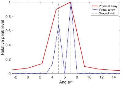
Fig. 1 demonstrates the improvement in angular resolution enabled by the virtual array. In this case there are two targets, at and angles and both at the same range. The red line shows the magnitude DFT of , with the location of the peaks indicating the angle estimates. The aperture of the receive array, i.e., , does not allow for the estimation of closely placed targets and thus only one peak shows up. The blue line shows the magnitude of of (17), with the peaks indicating the high resolution angle estimates. The virtual array is a sparse version of an array of aperture , thus, due to its higher resolution the targets can be resolved. For the virtual array based estimate, a grid of size was used. In this simulation, no noise was added.
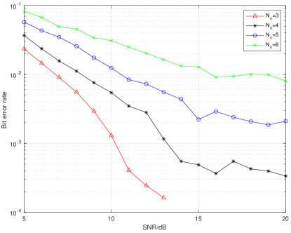
To evaluate the performance of the communication functionality we performed Monte Carlo simulations and calculated the bit error rates from data symbols and antenna indices encoding under different SNRs and different numbers of active antennas. Fig. 2 shows the performance of the communication system when applying the data symbol recovery method presented in Section III-A. For a fixed SNR, the fewer the activated antennas the smaller the BER is. This is because sparse signal recovery works better when the signal is sparser.
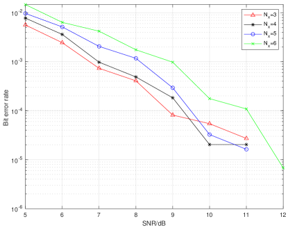
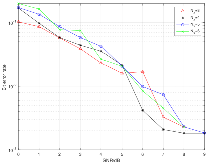
In Fig. 3 we plot the BER based on the received symbols, when the communication receiver applies the symbol and active antenna indices recovery method described in Sec. III-B, i.e., the private subcarriers and active antennas indices are identified first, and then the symbols are recovered via an LS approach. In comparison to Fig. 2, one can see that this approach achieves lower BER for the same SNR and the same value of . Indeed, the use of private subcarriers not only enables the construction of a virtual array for the radar system, but it also makes the communication system more robust to noise. The BER corresponding to the estimated antenna indices is shown in Fig. 4. In the simulations, the position bit stream was randomly generated and mapped to a dictionary to decide the indices of active antennas. One can see that the position encoding is robust to noise and the number of active antennas does not affect the result as in Fig. 2.
Under the configuration provided in the table, the maximum bit rate of the system with no private subcarriers is Gigabits per second, while the maximum bit rate of the same system with private subcarriers in every OFDM symbol is Gigabits per second. Thus, while the loss in bit rate from enabling private subcarrier is minor, the improvement in BER is significant.
VI Conclusion
We have proposed a novel MIMO-OFDM dual-function system using a sparse transmit array, whose active elements are selected in a GSM fashion. Most subcarriers are used in a shared fashion by the active antennas, except a set of subcarriers that are assigned to the transmit antennas in an exclusive fashion (private subcarriers). For the radar function, the system estimates angle, range and Doppler information using both private and shared subcarriers. The angle estimate is further improved by exploiting a virtual array constructed based on the private subcarriers. The communication system can use the private subcarriers to estimate active antenna indices and thus decode spatial information. Subcarrier sharing allows for high communication rates. The fact that only a small number of transmit antennas is active allows for low hardware cost of the DFRC system.
References
- [1] B. Li, A. P. Petropulu and W. Trappe, “Optimum co-design for spectrum sharing between matrix completion based MIMO radars and a MIMO communication system,” IEEE Transactions on Signal Processing , vol. 64, no. 17, pp. 4562-4575, 2016.
- [2] A. Hassanien, M. G. Amin, E. Aboutanios and B. Himed, “Dual-function radar communication systems: A solution to the spectrum congestion problem,” IEEE Signal Process. Mag., vol. 36, no. 5, pp. 115-126, 2019.
- [3] S. Sun, A. Petropulu and H. V. Poor, “MIMO radar for advanced driver-assistance systems and autonomous driving: Advantages and challenges,” IEEE Signal Process. Mag., vol. 37, no. 4, pp. 98-117, 2020.
- [4] K. V. Mishra, M.R. B. Shankar, V. Koivunen, B. Ottersten and S. A. Vorobyov, “Toward Millimeter-Wave Joint Radar Communications: A Signal Processing Perspective,” IEEE Signal Process. Mag., vol. 36, no. 5, pp. 100-114, 2019.
- [5] H. Wymeersch, G. Seco-Granados, G. Destino, D. Dardari and F. Tufvesson, “5G mmWave positioning for vehicular networks,” IEEE Wireless Communications, vol. 24, no. 6, pp. 80-86, 2017.
- [6] J. Li and P. Stoica, “MIMO radar with colocated antennas,” IEEE Signal Process. Mag., vol. 24, no. 5, pp. 106–114, 2007.
- [7] X. Wang, A. Hassanien and M. G. Amin, “Dual-function MIMO radar communications system design via sparse array optimization,” IEEE Transactions on Aerospace and Electronic Systems, vol. 55, no. 3, pp. 1213-1226, 2019.
- [8] Y. Rong, A. R. Chiriyath and D. W. Bliss, “MIMO radar and communications spectrum sharing: a multiple-access perspective,“ IEEE 10th Sensor Array and Multichannel Signal Processing Workshop (SAM), Sheffield, 2018.
- [9] M. Rossi, A. Haimovich, and Y. Eldar, “Spatial compressive sensing for MIMO radar,” IEEE Trans. Signal Process., vol. 62, no. 2, pp. 419–430, 2014.
- [10] R. Y. Mesleh, H. Haas, S. Sinanovic, C. W. Ahn and S. Yun, “Spatial Modulation,“ IEEE Transactions on Vehicular Technology, vol. 57, no. 4, pp. 2228-2241, July 2008.
- [11] M. Di Renzo, H. Haas, A. Ghrayeb, S. Sugiura and L. Hanzo, “Spatial modulation for generalized MIMO: Challenges, Opportunities, and Implementation,” in Proceedings of the IEEE, vol. 102, no. 1, pp. 56-103, 2014.
- [12] T. Huang, X. Xu, Y. Liu, N. Shlezinger and Y. C. Eldar, “A dual-function radar communication system using index modulation,” 2019 IEEE 20th International Workshop on Signal Processing Advances in Wireless Communications (SPAWC), Cannes, France, 2019.
- [13] A. Garcia-Rodriguez and C. Masouros, “Low-complexity compressive sensing detection for spatial modulation in large-scale multiple access channels,” IEEE Transactions on Communications, vol. 63, no. 7, pp. 2565-2579, 2015.
- [14] L. Xiao and et al., “Efficient compressive sensing detectors for generalized spatial modulation systems,” IEEE Trans. Veh. Technol., vol. 66, no. 2, pp. 1284–1298, 2017.
- [15] C. Sturm and W. Wiesbeck, “Waveform design and signal processing aspects for fusion of wireless communications and radar sensing,” Proceedings of the IEEE, vol. 99, no. 7, pp. 1236-1259, 2011.
- [16] Y. Liu, G. Liao and Z. Yang, “Range and angle estimation for MIMO-OFDM integrated radar and communication systems,” 2016 CIE International Conference on Radar (RADAR), Guangzhou, 2016.
- [17] F. Liu, C. Masouros, A. Petropulu, H. Griffiths and L. Hanzo, “Joint radar and communication design: applications, state-of-the-art, and the road ahead,” IEEE Transactions on Communications, in press, 2020.