This paper was converted on www.awesomepapers.org from LaTeX by an anonymous user.
Want to know more? Visit the Converter page.

A Color Elastica Model for Vector-Valued Image Regularization

Hao Liu , Xue-Cheng Tai , Ron Kimmel , Roland Glowinski School of Mathematics, Georgia Institute of Technology, Atlanta, GA 30332, USA. Email: [email protected] of Mathematics, Hong Kong Baptist University, Kowloon Tong, Hong Kong. Email: [email protected] Science Department, Technion, Haifa, Israel. Email: [email protected] of Mathematics, University of Houston, Honston, TX 77204, USA. Email: [email protected], and Department of Mathematics, Hong Kong Baptist University, Kowloon Tong, Hong Kong.
Abstract

Models related to the Euler’s elastica energy have proven to be useful for many applications including image processing. Extending elastica models to color images and multi-channel data is a challenging task, as stable and consistent numerical solvers for these geometric models often involve high order derivatives. Like the single channel Euler’s elastica model and the total variation (TV) models, geometric measures that involve high order derivatives could help when considering image formation models that minimize elastic properties. In the past, the Polyakov action from high energy physics has been successfully applied to color image processing. Here, we introduce an addition to the Polyakov action for color images that minimizes the color manifold curvature. The color image curvature is computed by applying of the Laplace–Beltrami operator to the color image channels. When reduced to gray-scale images, while selecting appropriate scaling between space and color, the proposed model minimizes the Euler’s elastica operating on the image level sets. Finding a minimizer for the proposed nonlinear geometric model is a challenge we address in this paper. Specifically, we present an operator-splitting method to minimize the proposed functional. The non-linearity is decoupled by introducing three vector-valued and matrix-valued variables. The problem is then converted into solving for the steady state of an associated initial-value problem. The initial-value problem is time-split into three fractional steps, such that each sub-problem has a closed form solution, or can be solved by fast algorithms. The efficiency and robustness of the proposed method are demonstrated by systematic numerical experiments.

1 Introduction

In image processing and computer vision, a fundamental question related to denoising and enhancing the quality of given images is what is the appropriate metric. In the literature, image regularization for gray-scale images has been extensively studied. One class of such models takes advantage of the Euler elastica energy defined by [19, p.63]

E(v)=Ω(1+β(v|v|)2)|v|𝑑𝐱,\displaystyle E(v)=\int_{\Omega}\left(1+\beta\left(\nabla\cdot\frac{\nabla v}{|\nabla v|}\right)^{2}\right)|\nabla v|d\mathbf{x}, (1)

where v:Ω+v:\Omega\rightarrow\mathbb{R}^{+} is a gray-scale image given as a function on a bounded domain Ω2\Omega\subset\mathbb{R}^{2}, d𝐱=dx1dx2d\mathbf{x}=dx_{1}dx_{2}, with x1,x2x_{1},x_{2} the coordinates of the generic point 𝐱\mathbf{x} of Ω\Omega, while aa and bb are two positive scalar model parameters.

Euler’s elastica has a wide range of uses in image processing, such as image denoising [21, 38, 47], image segmentation [2, 11, 46, 49], image inpainting [35, 38, 45], and image segmentation with depth [13, 27, 48], to name just a few. An important image denoising model, incorporating the Euler’s elastica energy, is

minvΩ(1+β(v|v|)2)v|d𝐱+12ηΩ|fv|2d𝐱,\displaystyle\min_{v}\int_{\Omega}\left(1+\beta\left(\nabla\cdot\frac{\nabla v}{|\nabla v|}\right)^{2}\right)\nabla v|d\mathbf{x}+\frac{1}{2\eta}\int_{\Omega}|f-v|^{2}d\mathbf{x}, (2)

where f:Ω+f:\Omega\rightarrow\mathbb{R}^{+} is the input image we would like to enhance and denoise. To find the minimizer of (2), one class of methods is based on the augmented Lagrangian method. In [38], an augmented Lagrangian method was proposed for image denoising, inpainting and zooming. Based on the method in [38], [12] suggested a fast augmented Lagrangian method and [47] proposed a linearized augmented Lagarangian method. A split-Bregman method was suggested in [45] to solve a linearized elastica model introduced in [1]. Recently, an almost ‘parameter free’ operator-splitting method was presented in [9]; this method is efficient, robust, and has less parameters to adjust compared to augmented Lagrangian based methods.

A color image is a vector-valued signal which can be represented, for example, by three RGB channels or four CMYK channels. While there are many papers and models that deal with gray-scale image regularization, most of them can not be trivially extended to handle color images when taking the geometric properties of the color image into consideration. Inspired by an early paper [10] that focused on regularization functionals on vector-valued images, [34] proposed an anisotropic diffusion framework and [5] introduced a color TV norm for vector-valued images. Another generalization of the scalar TV, known as the vectorial total variation, was proposed in [33] and studied in [20]. A total curvature model was proposed in [39], in which the color TV term in [5] is replaced by the sum of the curvatures of each channel. A generic anisotropic diffusion framework which unifies several PDE based methods was studied in [40]. The Beltrami framework was proposed in [36], it considers the image as a two-dimensional manifold embedded in a five-dimensional space-color (x,y,R,G,B)(x,y,R,G,B) space. The image is regularized by minimizing the Polyakov action [28], a surface area related functional. Evolving the image according to the Euler–Lagrange equation of the functional gives rise to the Beltrami flow. To accelerate the convergence rate of the Beltrami flow, a fixed-point method was used in [3] and a vector-extrapolation method was explored in [29]. In [37], the authors used a short-time kernel of the Beltrami flow to selectively smooth two-dimensional images on manifolds. Later on, a semi-implicit operator-splitting method [30] and an ALM based method [31] were proposed to minimize the Polyakov action for processing images. In [50], the authors used a primal-dual projection gradient method to solve a simplified Beltrami functional. A fidelity-Beltrami-sparsity model was proposed in [42], in which a sparsity penalty term was added to the Polyakov action. A generalized gradient operator for vector bundles was introduced in [4], which is applied in vector-valued image regularization. In [6], the Beltrami framework has been applied in active contour for image segmentation. Finally, in [32, 43] the Beltrami framework was extended to deal with patch based geometric flows, or anisotropic diffusion in patch space.

Most existing models for vector-valued image regularization contain only first order derivatives, like the Polyakov action [36], color TV [5] and vectorial TV [20]. This maybe insufficient when considering image formation models containing geometric properties, like the curvature as captured in the single channel Euler’s elastica model. The Polyakov action was shown to be a natural measure which minimization leads to selective smoothing filters for color images. To enrich the variety of image formation models, here, we propose a color elastica model which incorporates the Polyakov action and a Laplace–Beltrami operator acting on the image channels, as a way to regularize color images. While the Polyakov action measures the area of the image manifold, the surface elastica can be computed by applying the Laplace–Beltrami operator on the color channels. It describes a second order geometric structure that allows for more flexibility of the color image manifold and could relax the over-restrictive area minimization. The new model is a natural extension of the Euler elastica model (2) to color images, which takes the geometrical relation between channels into account. Compared to the Polyakov action model, the suggested model is more challenging to minimize since the Laplace–Beltrami term involves high order nonlinear terms. Here, we use an operator-splitting method to find the minimizer of the proposed model. To decouple the non-linearity, three vector-valued and matrix-valued variables are introduced. Then, finding the minimizer of the proposed model can be shown to be equivalent to solving a time-dependent PDE system until the steady state is reached. The PDE system is time-discretized by the operator-splitting method such that each sub-problem can be solved efficiently. To the best of our knowledge, this is the first numerical method to solve the color elastica model. Unlike deep learning methods, the suggested model does not require training, though the model itself could be used as an unsupervised loss in general settings. Numerical experiments show that the proposed model is effective in selectively smoothing color images, while keeping sharp edges.

While the model we propose may not outperform some existing methods like the BM3D [8] and some other deep learning methods [25, 44, 24] on vector-valued image regularization, it manifests properties which have simple geometric interpretations of images. The proposed model provides a new perspective on how to regularize vector-valued images and can be used in many other image processing applications, like image inpainting and segmentation, or as a semi-supervised regularization loss in network based denoising and deblurring. In addition, the model and algorithm proposed here could be also important for many other applications with vector-valued functions that need to be regularized. Many inverse problems, surface processing and image construction problems need this.

The rest of this paper is structured as follows: In Section 2, we briefly review the Polyakov action and the Beltrami framework. The color elastica model is introduced in Section 3. We derive the operator-splitting scheme in Section 4 and describe its finite difference discretization in Section 5. In Section 6, we demonstrate the efficiency, and robustness of the proposed method by systematic numerical experiments. We conclude the paper in Section 7.

2 The Polyakov action

In this section we briefly review the Riemannian geometry relevant to the Polyakov action as applied to color images. Since the Polyakov action is adopted from high energy physics, we temporarily follow the Einstein’s summation notation convention in this section. We first introduce the metric on the Riemannian manifold. Denote a two-dimensional Riemannian manifold embedded in d\mathds{R}^{d} by Σ\Sigma. Let (σ1,σ2)(\sigma^{1},\sigma^{2}) be a local coordinate system of Σ\Sigma and F(σ1,σ2)=(F1(σ1,σ2),,Fd(σ1,σ2))F(\sigma^{1},\sigma^{2})=(F^{1}(\sigma^{1},\sigma^{2}),...,F^{d}(\sigma^{1},\sigma^{2})) be the embedding of Σ\Sigma into d\mathds{R}^{d}. Given a metric {gij}\{g_{ij}\} for i,j=1,2i,j=1,2, of Σ\Sigma which is a symmetric positive definite matrix-valued metric tensor, the squared geodesic distance (ds)2(ds)^{2} on Σ\Sigma between two points (σ1,σ2)(\sigma^{1},\sigma^{2}) and (σ1+dσ1,σ2+dσ2)(\sigma^{1}+d\sigma^{1},\sigma^{2}+d\sigma^{2}) is defined by,

(ds)2=gμνdσμdσνg11(dσ1)2+2g12dσ1dσ2+g22(dσ2)2.\displaystyle(ds)^{2}=g_{\mu\nu}d\sigma^{\mu}d\sigma^{\nu}\equiv g_{11}(d\sigma^{1})^{2}+2g_{12}d\sigma^{1}d\sigma^{2}+g_{22}(d\sigma^{2})^{2}.

Assume FF embeds Σ\Sigma into a dd-dimensional Riemannian manifold MM with metric {hij},i,j=1,,d\{h_{ij}\},i,j=1,...,d. If {hij}\{h_{ij}\} is known, we can deduce the metric of Σ\Sigma by the pullback,

gij(σ1,σ2)=hμνiFμjFν,\displaystyle g_{ij}(\sigma^{1},\sigma^{2})=h_{\mu\nu}\partial_{i}F^{\mu}\partial_{j}F^{\nu}, (3)

where i\partial_{i} denotes the partial derivative with respect to the ithi^{\mbox{th}} coordinate, i/σi\partial_{i}\equiv\partial/\partial\sigma^{i}.

Consider a color image 𝐟(σ1,σ2)=(f1,f2,f3)\mathbf{f}(\sigma^{1},\sigma^{2})=(f_{1},f_{2},f_{3}) where (σ1,σ2)(\sigma^{1},\sigma^{2}) denote the spatial coordinates in the image domain, and f1,f2,f3f_{1},f_{2},f_{3} denote the RGB color components. 𝐟\mathbf{f} can be considered as a two-dimensional surface embedded in the five-dimensional space-feature space: F=(ασ1,ασ2,f1,f2,f3)F=(\sqrt{\alpha}\sigma^{1},\sqrt{\alpha}\sigma^{2},f_{1},f_{2},f_{3}), where α>0\alpha>0 is a scalar parameter controlling the ratio between the space and color. Assuming the spatial and color spaces to be Euclidean, we have hij=δijh_{ij}=\delta_{ij} on the space-feature space, where δij\delta_{ij} is the Kronecker delta, δij=1\delta_{ij}=1 if i=ji=j and δij=0\delta_{ij}=0 otherwise. Set σ1=x1,σ2=x2\sigma^{1}=x_{1},\sigma^{2}=x_{2}. According to (3), the metric on the image manifold is

𝐆{gij}=(α+k=13(1fk)2k=131fk2fkk=131fk2fkα+k=13(2fk)2).\displaystyle\mathbf{G}\equiv\{g_{ij}\}=\begin{pmatrix}\alpha+\sum_{k=1}^{3}(\partial_{1}f_{k})^{2}&\sum_{k=1}^{3}\partial_{1}f_{k}\partial_{2}f_{k}\\ \sum_{k=1}^{3}\partial_{1}f_{k}\partial_{2}f_{k}&\alpha+\sum_{k=1}^{3}(\partial_{2}f_{k})^{2}\end{pmatrix}. (4)

Denote (Σ,g)(\Sigma,g) the image manifold and its metric, and (M,h)(M,h) its space-feature space and the metric on it. The weight of the mapping F:ΣMF:\Sigma\rightarrow M is measured by

S(F,gij,hμν)=dmσgdFg,h2\displaystyle S(F,g_{ij},h_{\mu\nu})=\int d^{m}\sigma\sqrt{g}\|dF\|_{g,h}^{2} (5)

for i,j=1,,dim(Σ)i,j=1,...,\dim(\Sigma) and μ,ν=1,,dim(M)\mu,\nu=1,...,\dim(M), where g=det(𝐆)g=\det(\mathbf{G}) and dXg,h2=iFμjFνgijhμν\|dX\|_{g,h}^{2}=\partial_{i}F^{\mu}\partial_{j}F^{\nu}g^{ij}h_{\mu\nu} with F=(F1,,Fdim(M))F=(F^{1},...,F^{\dim(M)}) and {gij}\{g^{ij}\} being the inverse of the image metric {gij}\{g_{ij}\}. With m=2,hij=δijm=2,h_{ij}=\delta_{ij}, the functional is known as the Polyakov action [28] in String Theory.

Substituting hij=δijh_{ij}=\delta_{ij} and (4) into (5) gives rise to

S(F)=g𝑑𝐱 where g=det(𝐆).\displaystyle S(F)=\int\sqrt{g}d\mathbf{x}\mbox{\,\,\,\,\,\,\,\,\, where\,\, }g=\det(\mathbf{G}). (6)

Minimizing (6) by variational gradient descent, yields the Beltrami flow [23],

Ftk=1g(g𝐆1Fk),\displaystyle F_{t}^{k}=\frac{1}{\sqrt{g}}\nabla\cdot(\sqrt{g}\mathbf{G}^{-1}\nabla F^{k}), (7)

where Fk\nabla F^{k} is a column vector by convention. The term on the right hand side of (7) is known as the Laplace–Beltrami operator applied to FkF^{k}.

Notations

In the rest of the paper, we will use regular letters to denote scalar-valued functions, and bold letters to denote vector-valued and matrix-valued functions.

3 Formulation of the color elastica model

We assume the domain Ω=[0,L1]×[0,L2]\Omega=[0,L_{1}]\times[0,L_{2}] to be a rectangle. Periodic boundary condition is a common condition in image processing. In this paper, we assume all variables (scalar-valued, vector-valued and matrix-valued) have the periodic boundary condition. Let 𝐟=(f1,,fd)T\mathbf{f}=(f_{1},...,f_{d})^{T} be the given dd-dimensional signal to be smoothed, in which each component fk:Ω+f_{k}:\Omega\rightarrow\mathds{R}^{+} represents a channel. Based on the Polyakov action (6), we define the color elastica model as,

min𝐯𝒱dΩ(1+βk=1d(Δgvk)2)g𝑑𝐱+12ηk=1dΩ|vkfk|2𝑑𝐱,\min_{\mathbf{v}\in\mathcal{V}^{d}}\int_{\Omega}\left(1+\beta\sum_{k=1}^{d}(\Delta_{g}v_{k})^{2}\right)\sqrt{g}d\mathbf{x}+\frac{1}{2\eta}\sum_{k=1}^{d}\int_{\Omega}|v_{k}-f_{k}|^{2}d\mathbf{x}, (8)

where 𝐯=(v1,,vd)T:Ωd\mathbf{v}=(v_{1},...,v_{d})^{T}:\Omega\rightarrow\mathds{R}^{d}, β,η>0\beta,\eta>0 are weight parameters, 𝒱\mathcal{V} denotes the Sobolev space with periodic boundary condition P2(Ω)\mathcal{H}^{2}_{P}(\Omega) on Ω\Omega:

P2(Ω)=\displaystyle\mathcal{H}^{2}_{P}(\Omega)= {f2(Ω):f(0,:)=f(L1,:),f(:,0)=f(:,L2),\displaystyle\big{\{}f\in\mathcal{H}^{2}(\Omega):f(0,:)=f(L_{1},:),f(:,0)=f(:,L_{2}),
f(0,:)=f(L1,:),f(:,0)=f(:,L2)}.\displaystyle\quad\nabla f(0,:)=\nabla f(L_{1},:),\nabla f(:,0)=\nabla f(:,L_{2})\big{\}}.

Similar to (4), let 𝐆=(gkr)1k,r2\mathbf{G}=(g_{kr})_{1\leq k,r\leq 2} be a symmetric positive-definite metric matrix depending on 𝐯\mathbf{v}, where,

g11=α+k=1d|vix1|2,g12=g21=k=1dvkx1vkx2,g22=α+k=1d|vkx2|2,\displaystyle g_{11}=\alpha+\sum_{k=1}^{d}\left|\frac{\partial v_{i}}{\partial x_{1}}\right|^{2},\ g_{12}=g_{21}=\sum_{k=1}^{d}\frac{\partial v_{k}}{\partial x_{1}}\frac{\partial v_{k}}{\partial x_{2}},\ g_{22}=\alpha+\sum_{k=1}^{d}\left|\frac{\partial v_{k}}{\partial x_{2}}\right|^{2},

for some α>0\alpha>0. We denote g=det𝐆g=\det\mathbf{G}. Δg\Delta_{g} in (8) is the Laplace–Beltrami operator associated to 𝐆\mathbf{G},

Δgϕ=1g(g𝐆1ϕ),ϕV.\Delta_{g}\phi\,=\,\frac{1}{\sqrt{g}}\nabla\cdot(\sqrt{g}\mathbf{G}^{-1}\nabla\phi),\,\,\,\,\forall\phi\in V. (9)

Here, we consider the case d=3d=3 for color images: 𝐟=(f1,f2,f3)T\mathbf{f}=(f_{1},f_{2},f_{3})^{T} whose components represent the RGB channels. Then 𝐆\mathbf{G} is the metric of the surface F(x1,x2)=(αx1,αx2,v1,v2,v3F(x_{1},x_{2})=(\sqrt{\alpha}x_{1},\sqrt{\alpha}x_{2},v_{1},v_{2},v_{3} induced by the denoised image 𝐯\mathbf{v}.

Remark 3.1.

As described in Section 2, α\alpha represents the ratio between the spatial and feature coordinates. As α\alpha goes to 0, the ratio vanishes and the space-feature space reduces to the three-dimensional color space.

Remark 3.2.

When ff is a gray-scale image, dividing the first integral by α\sqrt{\alpha}, model (8) reduces to

E~α(v)Ωα+(vx2+vy2)𝑑𝐱+βΩ1α+(vx2+vy2)(vα+vx2+vy2)2𝑑𝐱\displaystyle\tilde{E}_{\alpha}(v)\equiv\int_{\Omega}\sqrt{\alpha+(v_{x}^{2}+v_{y}^{2})}d\mathbf{x}+\beta\int_{\Omega}\frac{1}{\sqrt{\alpha+(v_{x}^{2}+v_{y}^{2})}}\left(\nabla\cdot\frac{\nabla v}{\sqrt{\alpha+v_{x}^{2}+v_{y}^{2}}}\right)^{2}d\mathbf{x}
+12ηΩ|vf|2𝑑𝐱.\displaystyle\hskip 28.45274pt+\frac{1}{2\eta}\int_{\Omega}|v-f|^{2}d\mathbf{x}. (10)

As α0\alpha\rightarrow 0, (10) becomes

E~0(v)=Ω|v|𝑑𝐱+βΩ1|v|(v|v|)2𝑑𝐱+12ηΩ|vf|2𝑑𝐱\displaystyle\tilde{E}_{0}(v)=\int_{\Omega}|\nabla v|d\mathbf{x}+\beta\int_{\Omega}\frac{1}{|\nabla v|}\left(\nabla\cdot\frac{\nabla v}{|\nabla v|}\right)^{2}d\mathbf{x}+\frac{1}{2\eta}\int_{\Omega}|v-f|^{2}d\mathbf{x} (11)

which gives a variant of the elastica model (2), except that in (11) the weights depend on |v||\nabla v|. In other words, along the edges, the effect of the elastica term would be reduced.

Remark 3.3.

In the one channel case, the Polyakov action relates closely to existing models. As α0\alpha\rightarrow 0, the Polyakov action converges to the TV model, and the corresponding gradient flow converges to a level set mean curvature flow. As α\alpha\rightarrow\infty, the gradient flow of the Polyakov action converges to a diffusion process, i.e., Gaussian smoothing. In the multi-channel case, the Polyakov action contains interactions between channels. By letting α0\alpha\rightarrow 0, the Polyakov action does not reduce to the color TV model suggested in [5]. The color area minimization also tries to remove potential torsion of the image manifold and align the gradient directions of different channels. Correspondingly, its gradient flow converges to the mean curvature flow in the color space. Thus, the Polyakov action can be thought of as a natural extension of the TV model in the multi-channel case. By adding the Laplace-Betrami operator (LBO) acting on the color channels to the Polyakov action, the proposed color elastica model becomes a natural extension of the Euler’s elastica model, since it reduces to the Euler’s elastica model in one-channel case as α0\alpha\rightarrow 0. Moreover, when α0\alpha\rightarrow 0 the measure we end up with captures the area of the image manifold in the RGBRGB space for which the minimization is a mean curvature flow. The new term we add is the LBO acting on the RGBRGB coordinates which is, in fact, the mean curvature vector of the RGBRGB surface, here denoted by Δg𝐯\Delta_{g}{\bf v}. Thus, we end up minimizing the squared value of the mean curvature Ω(1+β|Δg𝐯|2)𝑑a\int_{\Omega}(1+\beta|\Delta_{g}{\bf v}|^{2})da for da=gd𝐱da=\sqrt{g}d{\bf x}.

The energy in (8) is nonlinear and is difficult to minimize, since it contains the determinate and inverse of a Hessian matrix. To simplify the nonlinearity, we introduce three vector-valued and matrix-valued variables. For k=1,2,3k=1,2,3 and r=1,2r=1,2, let us denote by qkrq_{kr} the real valued function vkxr\frac{\partial v_{k}}{\partial x_{r}} and by 𝐪\mathbf{q} the 3×23\times 2 Jacobian matrix

𝐪=(q11q12q21q22q31q32)=𝐯.\displaystyle\mathbf{q}=\begin{pmatrix}q_{11}&q_{12}\\ q_{21}&q_{22}\\ q_{31}&q_{32}\end{pmatrix}=\nabla\mathbf{v}.

Denote 𝐪k=(qk1qk2),k=1,2,3\mathbf{q}_{k}=\begin{pmatrix}q_{k1}&q_{k2}\end{pmatrix},k=1,2,3. We introduce the 3×23\times 2 matrix 𝝁=g𝐪𝐆1\bm{\mu}=\sqrt{g}\mathbf{q}\mathbf{G}^{-1} with

𝝁k=g𝐪k𝐆1\bm{\mu}_{k}=\sqrt{g}\mathbf{q}_{k}\mathbf{G}^{-1} (12)

for each row of 𝝁\bm{\mu}. We immediately have 𝐪k=1g𝝁k𝐆\mathbf{q}_{k}=\frac{1}{\sqrt{g}}\bm{\mu}_{k}\mathbf{G}. We shall use 𝐌(𝐪)\mathbf{M}(\mathbf{q}) to be the matrix-valued function defined by

𝐌(𝐪)=(α+q112+q212+q312q11q12+q21q22+q31q32q11q12+q21q22+q31q32α+q122+q222+q322),\displaystyle\mathbf{M}(\mathbf{q})=\begin{pmatrix}\alpha+q_{11}^{2}+q_{21}^{2}+q_{31}^{2}&q_{11}q_{12}+q_{21}q_{22}+q_{31}q_{32}\\ q_{11}q_{12}+q_{21}q_{22}+q_{31}q_{32}&\alpha+q_{12}^{2}+q_{22}^{2}+q_{32}^{2}\end{pmatrix}, (13)

and denote det𝐌(𝐪)\det\mathbf{M}(\mathbf{q}) by m(𝐪)m(\mathbf{q}), that is,

m(𝐪)=det𝐌(𝐪).m(\mathbf{q})=\det\mathbf{M}(\mathbf{q}).

Define 𝐯𝐪={(v𝐪)k}k=13\mathbf{v}_{\mathbf{q}}=\{(v_{\mathbf{q}})_{k}\}_{k=1}^{3} to be the solution of

{2(v𝐪)k=𝐪k in Ω,(v𝐪)k has the periodic boundary condition on Ω,Ω(v𝐪)k𝑑x=Ωfk𝑑xfor k=1,2,3.\begin{cases}\nabla^{2}(v_{\mathbf{q}})_{k}\,=\,\nabla\cdot\mathbf{q}_{k}&\mbox{ in }\Omega,\\ (v_{\mathbf{q}})_{k}\mbox{ has the periodic boundary condition}&\mbox{ on }\partial\Omega,\\ \int_{\Omega}(v_{\mathbf{q}})_{k}dx\,=\,\int_{\Omega}f_{k}dx\\ \mbox{for }k=1,2,3.\end{cases} (14)

Denote

P2={f2(Ω):f(0,:)=f(L1,:),f(:,0)=f(:,L2),\displaystyle\mathcal{L}_{P}^{2}=\{f\in\mathcal{L}^{2}(\Omega):f(0,:)=f(L_{1},:),f(:,0)=f(:,L_{2}),
P1={f1(Ω):f(0,:)=f(L1,:),f(:,0)=f(:,L2).\displaystyle\mathcal{H}_{P}^{1}=\{f\in\mathcal{H}^{1}(\Omega):f(0,:)=f(L_{1},:),f(:,0)=f(:,L_{2}).

We define the sets Σf\Sigma_{f} and S𝐩S_{\mathbf{p}} as

Σf={𝐪(P2(Ω))3×2:𝐯(P1(Ω))3 such that 𝐪=𝐯\displaystyle\Sigma_{f}=\Big{\{}\mathbf{q}\in(\mathcal{L}^{2}_{P}(\Omega))^{3\times 2}:\exists\mathbf{v}\in(\mathcal{H}^{1}_{P}(\Omega))^{3}\mbox{ such that }\mathbf{q}=\nabla\mathbf{v}
 and Ω(vkfk)dx=0 for k=1,2,3},\displaystyle\hskip 142.26378pt\mbox{ and }\int_{\Omega}(v_{k}-f_{k})dx=0\mbox{ for }k=1,2,3\Big{\}}, (15)
S𝐆={(𝐪,𝝁)((P2(Ω))3×2,(P2(Ω))3×2):𝝁k=g𝐪k𝐆1,k=1,2,3 with g=det𝐆}\displaystyle S_{\mathbf{G}}=\left\{(\mathbf{q},\bm{\mu})\in\left((\mathcal{L}^{2}_{P}(\Omega))^{3\times 2},(\mathcal{L}^{2}_{P}(\Omega))^{3\times 2}\right):\bm{\mu}_{k}=\sqrt{g}\mathbf{q}_{k}\mathbf{G}^{-1},k=1,2,3\mbox{ with }g=\det\mathbf{G}\right\} (16)

and their corresponding indicator functions as

IΣf(𝐪)={0, if 𝐪Σf,, otherwise,IS𝐆(𝐪,𝝁)={0, if (𝐪,𝝁)S𝐆,, otherwise.\displaystyle I_{\Sigma_{f}}(\mathbf{q})=\begin{cases}0,&\mbox{ if }\mathbf{q}\in\Sigma_{f},\\ \infty,&\mbox{ otherwise},\end{cases}\hskip 28.45274ptI_{S_{\mathbf{G}}}(\mathbf{q},\bm{\mu})=\begin{cases}0,&\mbox{ if }(\mathbf{q},\bm{\mu})\in S_{\mathbf{G}},\\ \infty,&\mbox{ otherwise}.\end{cases}

If (𝐩,𝝀,𝐆)(\mathbf{p},\bm{\lambda},\mathbf{G}) is the minimizer of the following energy

{min𝝁,𝐪Ω(g+βgk=13|𝝁k|2)𝑑𝐱+12ηk=13Ω|(v𝐪)kfk|2𝑑𝐱+IΣf(𝐪)+IS𝐆(𝐪,𝝁),𝐆=𝐌(𝐪),\begin{cases}\min\limits_{\bm{\mu},\mathbf{q}}\displaystyle\int_{\Omega}\left(\sqrt{g}+\frac{\beta}{\sqrt{g}}\sum_{k=1}^{3}|\nabla\cdot\bm{\mu}_{k}|^{2}\right)d\mathbf{x}+\frac{1}{2\eta}\sum_{k=1}^{3}\displaystyle\int_{\Omega}|(v_{\mathbf{q}})_{k}-f_{k}|^{2}d\mathbf{x}\\ \hskip 56.9055pt+I_{\Sigma_{f}}(\mathbf{q})+I_{S_{\mathbf{G}}}(\mathbf{q},\bm{\mu}),\\ \mathbf{G}=\mathbf{M}(\mathbf{q}),\end{cases} (17)

then 𝐯\mathbf{v} solving (14) minimizes (8).

In (17), we rewrite the Laplace–Beltrami term as 𝝁k\nabla\cdot\bm{\mu}_{k} where 𝝁\bm{\mu} linearly depends on 𝐪\mathbf{q}. The metric g=det𝐌(𝐪)\sqrt{g}=\det\mathbf{M}(\mathbf{q}) is also a function of 𝐪\mathbf{q}. In the fidelity term, 𝐯\mathbf{v} which solves (14) can be uniquely determined by 𝐪\mathbf{q}. Thus the functional only depends on 𝝁\bm{\mu} and 𝐪\mathbf{q} under some constraints on their relations. We then remove the constraints by incorporating the functional with the two indicator function IΣf(𝐪)I_{\Sigma_{f}}(\mathbf{q}) and IS𝐆(𝐪,𝝁)I_{S_{\mathbf{G}}}(\mathbf{q},\bm{\mu}). The resulting problem (17) is an unconstrained optimization problem with respect to 𝝁\bm{\mu} and 𝐪\mathbf{q} only.

Remark 3.4.

While the periodic boundary condition is used in this paper, we would like to mention that zero Neumann boundary condition is another natural condition to consider. The model and algorithm proposed in this paper can be adapted to zero Neumann boundary condition with minor modification.

4 Operator splitting method

In this section, we derive the operator-splitting scheme to solve (17). We refer the readers to [18] for a complete introduction of the operator-splitting method and to [17] for its applications in image processing.

4.1 Optimality condition

Denote

J1(𝐪,𝝁,𝐆)=Ω(g+βgk=13|𝝁k|2)𝑑𝐱,\displaystyle J_{1}(\mathbf{q},\bm{\mu},\mathbf{G})=\int_{\Omega}\left(\sqrt{g}+\frac{\beta}{\sqrt{g}}\sum_{k=1}^{3}|\nabla\cdot\bm{\mu}_{k}|^{2}\right)d\mathbf{x}, (18)
J2(𝐪)=12ηk=13Ω|(v𝐪)kfk|2𝑑𝐱\displaystyle J_{2}(\mathbf{q})=\frac{1}{2\eta}\sum_{k=1}^{3}\int_{\Omega}|(v_{\mathbf{q}})_{k}-f_{k}|^{2}d\mathbf{x} (19)

with g=det𝐆g=\det\mathbf{G}. If (𝐩,𝝀,𝐆)(\mathbf{p},\bm{\lambda},\mathbf{G}) is the minimizer of (17), it satisfies

{𝐪J1(𝐩,𝝀)+𝐪J2(𝐩)+IΣf(𝐩)+𝐪IS𝐩(𝐩,𝝀)0,𝝁J1(𝐩,𝝀)+𝝁IS𝐆(𝐩,𝝀)0,𝐆𝐌(𝐩)=0,\begin{cases}\partial_{\mathbf{q}}J_{1}(\mathbf{p},\bm{\lambda})+\partial_{\mathbf{q}}J_{2}(\mathbf{p})+\partial I_{\Sigma_{f}}(\mathbf{p})+\partial_{\mathbf{q}}I_{S_{\mathbf{p}}}(\mathbf{p},\bm{\lambda})\ni 0,\\ \partial_{\bm{\mu}}J_{1}(\mathbf{p},\bm{\lambda})+\partial_{\bm{\mu}}I_{S_{\mathbf{G}}}(\mathbf{p},\bm{\lambda})\ni 0,\\ \mathbf{G}-\mathbf{M}(\mathbf{p})=0,\end{cases} (20)

where 𝐪\partial_{\mathbf{q}} denotes the partial derivative with respect to 𝐪\mathbf{q} if its operand is a smooth function, and the sub-derivative if its operand is an indicator function. To solve (20), we introduce the artificial time and associate it with the initial value problem

{𝐩t+𝐪J1(𝐩,𝝀,𝐆)+𝐪J2(𝐩,𝐆)+IΣf(𝐩)+𝐪IS𝐆(𝐩,𝝀)0,γ1𝝀t+𝝁J1(𝐩,𝝀)+𝝁IS𝐆(𝐩,𝝀)0,𝐆t+γ2(𝐆𝐌(𝐩))=0,(𝐩(0),𝝀(0),𝐆(0))=(𝐩0,𝝀0,𝐆0),\begin{cases}\frac{\partial\mathbf{p}}{\partial t}+\partial_{\mathbf{q}}J_{1}(\mathbf{p},\bm{\lambda},\mathbf{G})+\partial_{\mathbf{q}}J_{2}(\mathbf{p},\mathbf{G})+\partial I_{\Sigma_{f}}(\mathbf{p})+\partial_{\mathbf{q}}I_{S_{\mathbf{G}}}(\mathbf{p},\bm{\lambda})\ni 0,\\ \gamma_{1}\frac{\partial\bm{\lambda}}{\partial t}+\partial_{\bm{\mu}}J_{1}(\mathbf{p},\bm{\lambda})+\partial_{\bm{\mu}}I_{S_{\mathbf{G}}}(\mathbf{p},\bm{\lambda})\ni 0,\\ \frac{\partial\mathbf{G}}{\partial t}+\gamma_{2}(\mathbf{G}-\mathbf{M}(\mathbf{p}))=0,\\ (\mathbf{p}(0),\bm{\lambda}(0),\mathbf{G}(0))=(\mathbf{p}^{0},\bm{\lambda}^{0},\mathbf{G}^{0}),\end{cases} (21)

where (𝐩0,𝝀0,𝐆0)(\mathbf{p}^{0},\bm{\lambda}^{0},\mathbf{G}^{0}) is the initial condition which is supposed to be given, and γ1,γ2\gamma_{1},\gamma_{2} are positive constants controlling the evolution speed of 𝝀\bm{\lambda} and 𝐆\mathbf{G}, respectively. The choice of γ1\gamma_{1} will be discussed in Section 4.4.

4.2 Operator-splitting scheme

Similar to [16, 26, 15], we use an operator-splitting method to time discretize (21). One simple choice is the Lie scheme [19]. We denote nn as the iteration number, det𝐆n\det\mathbf{G}^{n} by gng^{n}, the time step by τ\tau and set tn=nτt^{n}=n\tau. Since J1(𝐪,𝝁,𝐆)J_{1}(\mathbf{q},\bm{\mu},\mathbf{G}) only contains gg, when there is no ambiguity, we write J1(𝐪,𝝁,𝐆)J_{1}(\mathbf{q},\bm{\mu},\mathbf{G}) and J1(𝐪,𝝁,g)J_{1}(\mathbf{q},\bm{\mu},g) interchangeably. We update 𝐩,𝝀,𝐆\mathbf{p},\bm{\lambda},\mathbf{G} as follows,
Initialization

Initialize 𝐩0,𝐆0,𝝀0 and compute g0=det𝐆0.\mbox{Initialize }\mathbf{p}^{0},\mathbf{G}^{0},\bm{\lambda}^{0}\mbox{ and compute }g^{0}=\det\mathbf{G}^{0}. (22)

Fractional step 1
Solve

{{𝐩t+𝐪J1(𝐩,𝝀,𝐆)𝟎,γ1𝝀t+𝝁J1(𝐩,𝝀,𝐆)=𝟎,𝐆t+γ23(𝐆𝐌(𝐩))=𝟎, in Ω×(tn,tn+1),(𝐩(tn),𝝀(tn),𝐆(tn))=(𝐩n,𝝀n,𝐆n)\begin{cases}\begin{cases}\frac{\partial\mathbf{p}}{\partial t}+\partial_{\mathbf{q}}J_{1}(\mathbf{p},\bm{\lambda},\mathbf{G})\ni\mathbf{0},\\ \gamma_{1}\frac{\partial\bm{\lambda}}{\partial t}+\partial_{\bm{\mu}}J_{1}(\mathbf{p},\bm{\lambda},\mathbf{G})=\mathbf{0},\\ \frac{\partial\mathbf{G}}{\partial t}+\frac{\gamma_{2}}{3}(\mathbf{G}-\mathbf{M}(\mathbf{p}))=\mathbf{0},\end{cases}\mbox{ in }\Omega\times(t^{n},t^{n+1}),\\ (\mathbf{p}(t^{n}),\bm{\lambda}(t^{n}),\mathbf{G}(t^{n}))=(\mathbf{p}^{n},\bm{\lambda}^{n},\mathbf{G}^{n})\end{cases} (23)

and set 𝐩n+1/3=𝐩(tn+1),𝝀n+1/3=𝝀(tn+1),𝐆n+1/3=𝐆(tn+1),gn+1/3=det𝐆n+1/3\mathbf{p}^{n+1/3}=\mathbf{p}(t^{n+1}),\bm{\lambda}^{n+1/3}=\bm{\lambda}(t^{n+1}),\mathbf{G}^{n+1/3}=\mathbf{G}(t^{n+1}),g^{n+1/3}=\det\mathbf{G}^{n+1/3}.

Fractional step 2
Solve

{{𝐩t+𝐪IS𝐆n+1/3(𝐩,𝝀)𝟎,γ1𝝀t+𝝁IS𝐆n+1/3(𝐩,𝝀)𝟎,𝐆t+γ23(𝐆𝐌(𝐩))=𝟎 in Ω×(tn,tn+1),(𝐩(tn),𝝀(tn),𝐆(tn))=(𝐩n+1/3,𝝀n+1/3,𝐆n+1/3)\begin{cases}\begin{cases}\frac{\partial\mathbf{p}}{\partial t}+\partial_{\mathbf{q}}I_{S_{\mathbf{G}^{n+1/3}}}(\mathbf{p},\bm{\lambda})\ni\mathbf{0},\\ \gamma_{1}\frac{\partial\bm{\lambda}}{\partial t}+\partial_{\bm{\mu}}I_{S_{\mathbf{G}^{n+1/3}}}(\mathbf{p},\bm{\lambda})\ni\mathbf{0},\\ \frac{\partial\mathbf{G}}{\partial t}+\frac{\gamma_{2}}{3}(\mathbf{G}-\mathbf{M}(\mathbf{p}))=\mathbf{0}\end{cases}\mbox{ in }\Omega\times(t^{n},t^{n+1}),\\ (\mathbf{p}(t^{n}),\bm{\lambda}(t^{n}),\mathbf{G}(t^{n}))=(\mathbf{p}^{n+1/3},\bm{\lambda}^{n+1/3},\mathbf{G}^{n+1/3})\end{cases} (24)

and set 𝐩n+2/3=𝐩(tn+1),𝝀n+2/3=𝝀(tn+1),𝐆n+2/3=𝐆(tn+1),gn+2/3=det𝐆n+2/3\mathbf{p}^{n+2/3}=\mathbf{p}(t^{n+1}),\bm{\lambda}^{n+2/3}=\bm{\lambda}(t^{n+1}),\mathbf{G}^{n+2/3}=\mathbf{G}(t^{n+1}),g^{n+2/3}=\det\mathbf{G}^{n+2/3}.

Fractional step 3
Solve

{{𝐩t+𝐪J2(𝐪)+𝐪IΣf(𝐩)𝟎,γ1𝝀t=𝟎,𝐆t+γ23(𝐆𝐌(𝐩))=𝟎 in Ω×(tn,tn+1),(𝐩(tn),𝝀(tn),𝐆(tn))=(𝐩n+2/3,𝝀n+2/3,𝐆n+2/3)\begin{cases}\begin{cases}\frac{\partial\mathbf{p}}{\partial t}+\partial_{\mathbf{q}}J_{2}(\mathbf{q})+\partial_{\mathbf{q}}I_{\Sigma_{f}}(\mathbf{p})\ni\mathbf{0},\\ \gamma_{1}\frac{\partial\bm{\lambda}}{\partial t}=\mathbf{0},\\ \frac{\partial\mathbf{G}}{\partial t}+\frac{\gamma_{2}}{3}(\mathbf{G}-\mathbf{M}(\mathbf{p}))=\mathbf{0}\end{cases}\mbox{ in }\Omega\times(t^{n},t^{n+1}),\\ (\mathbf{p}(t^{n}),\bm{\lambda}(t^{n}),\mathbf{G}(t^{n}))=(\mathbf{p}^{n+2/3},\bm{\lambda}^{n+2/3},\mathbf{G}^{n+2/3})\end{cases} (25)

and set 𝐩n+1=𝐩(tn+1),𝝀n+1=𝝀(tn+1),𝐆n+1=𝐆(tn+1),gn+1=det𝐆n+1\mathbf{p}^{n+1}=\mathbf{p}(t^{n+1}),\bm{\lambda}^{n+1}=\bm{\lambda}(t^{n+1}),\mathbf{G}^{n+1}=\mathbf{G}(t^{n+1}),g^{n+1}=\det\mathbf{G}^{n+1}.

Scheme (23)-(25) is only semi-discrete since we still need to solve the three sub-initial value problems. There is no difficulty in updating 𝐆\mathbf{G} in (23)-(25) if 𝐌(𝐩)\mathbf{M}(\mathbf{p}) is fixed, since we have the exact solution 𝐆(tn+1)=eγ2τ/3G(tn)+(1eγ2τ/3)M(𝐩)\mathbf{G}(t^{n+1})=e^{-\gamma_{2}\tau/3}G(t^{n})+(1-e^{-\gamma_{2}\tau/3})M(\mathbf{p}). To solve other subproblems, we suggest to use the Marchuk-Yanenko type discretization:
Initialize 𝐩0,𝐆0,𝝀0 and compute g0=det𝐆0\mathbf{p}^{0},\mathbf{G}^{0},\bm{\lambda}^{0}\mbox{ and compute }g^{0}=\det\mathbf{G}^{0}.

For n0n\geq 0, we update (𝐩n,𝝀n,𝐆n,gn)(𝐩n+1/3,𝝀n+1/3,𝐆n+1/3,gn+1/3)(\mathbf{p}^{n},\bm{\lambda}^{n},\mathbf{G}^{n},g^{n})\rightarrow(\mathbf{p}^{n+1/3},\bm{\lambda}^{n+1/3},\mathbf{G}^{n+1/3},g^{n+1/3})
(𝐩n+2/3,𝝀n+2/3,𝐆n+2/3,gn+2/3)(𝐩n+1,𝝀n+1,𝐆n+1,gn+1)\rightarrow(\mathbf{p}^{n+2/3},\bm{\lambda}^{n+2/3},\mathbf{G}^{n+2/3},g^{n+2/3})\rightarrow(\mathbf{p}^{n+1},\bm{\lambda}^{n+1},\mathbf{G}^{n+1},g^{n+1}) as:

{𝐩n+1/3𝐩nτ+𝐪J1(𝐩n+1/3,𝝀n,m(𝐩n+1/3))𝟎,𝐆n+1/3=eγ2τ/3𝐆n+(1eγ2τ/3)𝐌(𝐩n+1/3),gn+1/3=det𝐆n+1/3,𝝀n+1/3𝝀nτ+𝝁J1(𝐩n+1/3,𝝀n+1/3,gn+1/3)=𝟎.\displaystyle\begin{cases}\frac{\mathbf{p}^{n+1/3}-\mathbf{p}^{n}}{\tau}+\partial_{\mathbf{q}}J_{1}(\mathbf{p}^{n+1/3},\bm{\lambda}^{n},m(\mathbf{p}^{n+1/3}))\ni\mathbf{0},\\ \mathbf{G}^{n+1/3}=e^{-\gamma_{2}\tau/3}\mathbf{G}^{n}+(1-e^{-\gamma_{2}\tau/3})\mathbf{M}(\mathbf{p}^{n+1/3}),\\ g^{n+1/3}=\det\mathbf{G}^{n+1/3},\\ \frac{\bm{\lambda}^{n+1/3}-\bm{\lambda}^{n}}{\tau}+\partial_{\bm{\mu}}J_{1}(\mathbf{p}^{n+1/3},\bm{\lambda}^{n+1/3},g^{n+1/3})=\mathbf{0}.\end{cases} (26)
{𝐩n+2/3𝐩n+1/3τ+𝐪IS𝐆n+1/3(𝐩n+2/3,𝝀n+2/3)𝟎,γ1𝝀n+2/3𝝀n+1/3τ+𝝁IS𝐆n+1/3(𝐩n+2/3,𝝀n+2/3)𝟎,𝐆n+2/3=eγ2τ/3𝐆n+1/3+(1eγ2τ/3)𝐌(𝐩n+2/3),gn+2/3=det𝐆n+2/3,\displaystyle\begin{cases}\frac{\mathbf{p}^{n+2/3}-\mathbf{p}^{n+1/3}}{\tau}+\partial_{\mathbf{q}}I_{S_{\mathbf{G}^{n+1/3}}}(\mathbf{p}^{n+2/3},\bm{\lambda}^{n+2/3})\ni\mathbf{0},\\ \gamma_{1}\frac{\bm{\lambda}^{n+2/3}-\bm{\lambda}^{n+1/3}}{\tau}+\partial_{\bm{\mu}}I_{S_{\mathbf{G}^{n+1/3}}}(\mathbf{p}^{n+2/3},\bm{\lambda}^{n+2/3})\ni\mathbf{0},\\ \mathbf{G}^{n+2/3}=e^{-\gamma_{2}\tau/3}\mathbf{G}^{n+1/3}+(1-e^{-\gamma_{2}\tau/3})\mathbf{M}(\mathbf{p}^{n+2/3}),\\ g^{n+2/3}=\det\mathbf{G}^{n+2/3},\end{cases} (27)
{𝐩n+1𝐩n+2/3τ+𝐪J2(𝐩n+1)+𝐪IΣf(𝐩n+1)𝟎,𝐆n+1=eγ2τ/3𝐆n+2/3+(1eγ2τ/3)𝐌(𝐩n+1),gn+1=det𝐆n+1,𝝀n+1=𝝀n+2/3.\displaystyle\begin{cases}\frac{\mathbf{p}^{n+1}-\mathbf{p}^{n+2/3}}{\tau}+\partial_{\mathbf{q}}J_{2}(\mathbf{p}^{n+1})+\partial_{\mathbf{q}}I_{\Sigma_{f}}(\mathbf{p}^{n+1})\ni\mathbf{0},\\ \mathbf{G}^{n+1}=e^{-\gamma_{2}\tau/3}\mathbf{G}^{n+2/3}+(1-e^{-\gamma_{2}\tau/3})\mathbf{M}(\mathbf{p}^{n+1}),\\ g^{n+1}=\det\mathbf{G}^{n+1},\\ \bm{\lambda}^{n+1}=\bm{\lambda}^{n+2/3}.\end{cases} (28)

In the following subsections, we discuss the solution of each of the sub-PDE systems (26)-(28).

Remark 4.1.

Scheme (22)-(25) is an approximation of the gradient flow. Thus the convergence rate of the proposed scheme closely relates to that of the gradient flow together with an approximation error. It is shown that when there is only one variable and the operators in each step is smooth enough, the approximation error is of O(τ)O(\tau) (see [7] and [14, Chapter 6]). In this article, due to the complex structures of J1,J2,IΣfJ_{1},J_{2},I_{\Sigma_{f}} and IS𝐆I_{S_{\mathbf{G}}}, we cannot use existing tools to analyze the convergence rate and need to study it separately.

4.3 On the solution of (26)

If 𝐩n+1/3\mathbf{p}^{n+1/3} is the minimizer of the following problem, then the Euler-Lagrangian equation for it is exactly (26) and this means 𝐩n+1/3\mathbf{p}^{n+1/3} solves (26):

𝐩n+1/3=\displaystyle\mathbf{p}^{n+1/3}= argmin𝐪(P2(Ω))3×2[12τΩ|𝐪𝐩n|2dx\displaystyle\operatorname*{arg\,min}_{\mathbf{q}\in(\mathcal{L}^{2}_{P}(\Omega))^{3\times 2}}\Bigg{[}\frac{1}{2\tau}\int_{\Omega}|\mathbf{q}-\mathbf{p}^{n}|^{2}dx
+Ω(m(𝐪)+βm(𝐪)k=13|𝝀kn|2)d𝐱].\displaystyle\quad+\int_{\Omega}\left(\sqrt{m(\mathbf{q})}+\frac{\beta}{\sqrt{m(\mathbf{q})}}\sum_{k=1}^{3}|\nabla\cdot\bm{\lambda}^{n}_{k}|^{2}\right)d\mathbf{x}\Bigg{]}. (29)

This problem can be solved by Newton’s method. The functional in (29) is in the form of

E1=12τΩ|𝐪𝐩|2𝑑x+Ω(s1m(𝐪)+βs2m(𝐪))𝑑𝐱E_{1}=\frac{1}{2\tau}\int_{\Omega}|\mathbf{q}-\mathbf{p}|^{2}dx+\int_{\Omega}\left(s_{1}\sqrt{m(\mathbf{q})}+\frac{\beta s_{2}}{\sqrt{m(\mathbf{q})}}\right)d\mathbf{x} (30)

for some s1,s20,𝐩(P2(Ω))3×2s_{1},s_{2}\geq 0,\mathbf{p}\in(\mathcal{L}^{2}_{P}(\Omega))^{3\times 2}. The first and second order variation of E1E_{1} with respect to qkr,k=1,2,r=1,2,3q_{kr},k=1,2,r=1,2,3 are

E1qkr(𝐪,𝐩)=1τ(qkrpkr)+12(s1(m(𝐪))12βs2(m(𝐪))32)m(𝐪)qkr,\displaystyle\frac{\partial E_{1}}{\partial q_{kr}}(\mathbf{q},\mathbf{p})=\frac{1}{\tau}(q_{kr}-p_{kr})+\frac{1}{2}\left(s_{1}(m(\mathbf{q}))^{-\frac{1}{2}}-\beta s_{2}(m(\mathbf{q}))^{-\frac{3}{2}}\right)\frac{\partial m(\mathbf{q})}{\partial q_{kr}}, (31)
2E1qkr2(𝐪,𝐩)=1τ+12(s1(m(𝐪))12βs2(m(𝐪))32)2m(𝐪)qkr2+12(12s1(m(𝐪))32+32βs2(m(𝐪))52)(m(𝐪)qkr)2\displaystyle\begin{aligned} \frac{\partial^{2}E_{1}}{\partial q_{kr}^{2}}(\mathbf{q},\mathbf{p})=&\frac{1}{\tau}+\frac{1}{2}\left(s_{1}(m(\mathbf{q}))^{-\frac{1}{2}}-\beta s_{2}(m(\mathbf{q}))^{-\frac{3}{2}}\right)\frac{\partial^{2}m(\mathbf{q})}{\partial q_{kr}^{2}}\\ &\quad\quad+\frac{1}{2}\left(-\frac{1}{2}s_{1}(m(\mathbf{q}))^{-\frac{3}{2}}+\frac{3}{2}\beta s_{2}(m(\mathbf{q}))^{-\frac{5}{2}}\right)\left(\frac{\partial m(\mathbf{q})}{\partial q_{kr}}\right)^{2}\end{aligned} (32)

with

m(𝐪)qk1=2g22qk12g12qk2,\displaystyle\frac{\partial m(\mathbf{q})}{\partial q_{k1}}=2g_{22}q_{k1}-2g_{12}q_{k2}, m(𝐪)qk2=2g11qk22g12qk1,\displaystyle\frac{\partial m(\mathbf{q})}{\partial q_{k2}}=2g_{11}q_{k2}-2g_{12}q_{k1}, (33)
2m(𝐪)qk12=2g222qk22,\displaystyle\frac{\partial^{2}m(\mathbf{q})}{\partial q_{k1}^{2}}=2g_{22}-2q_{k2}^{2}, 2m(𝐪)qk22=2g112qk12\displaystyle\frac{\partial^{2}m(\mathbf{q})}{\partial q_{k2}^{2}}=2g_{11}-2q_{k1}^{2} (34)

for k=1,2,3k=1,2,3. From an initial guess of 𝐪0\mathbf{q}^{0}, qkrq_{kr} is updated by

qkrω+1=qkrωE1qkr(𝐪ω,𝐩)2E1qkr2(𝐪ω,𝐩)q_{kr}^{\omega+1}=q_{kr}^{\omega}-\frac{\frac{\partial E_{1}}{\partial q_{kr}}(\mathbf{q}^{\omega},\mathbf{p})}{\frac{\partial^{2}E_{1}}{\partial q_{kr}^{2}}(\mathbf{q}^{\omega},\mathbf{p})} (35)

until maxk,r|qkrω+1qkrω|<tol\max_{k,r}|q_{kr}^{\omega+1}-q_{kr}^{\omega}|_{\infty}<tol for some stopping criterion toltol. Then we set qkrn+1/3=qkrq^{n+1/3}_{kr}=q^{*}_{kr} where qkrq^{*}_{kr} is the converged variable.

Remark 4.2.

In our algorithm, the initial guess of 𝐪0\mathbf{q}^{0} is set to be 𝐩n\mathbf{p}^{n}, the minimizer of (29) in the previous iteration. As long as the time step is small enough, 𝐩n\mathbf{p}^{n} and 𝛌n\bm{\lambda}^{n} are close to 𝐩n1\mathbf{p}^{n-1} and 𝛌n1\bm{\lambda}^{n-1}, respectively. Thus, the functional in (29) does not change too much from that in the previous iteration. It is reasonable to expect its minimizer is close to 𝐩n\mathbf{p}^{n}, and 𝐩n\mathbf{p}^{n} is a good initial guess. This is verified in our numerical experiments.

For 𝝀n+1/3\bm{\lambda}^{n+1/3}, it is the solution to

{𝝀n+1/3={𝝀kn+1/3}k=13(P1(Ω))3×2,γ1Ω𝝀kn+1/3𝝁k𝑑x+2βτΩ(𝝀kn+1/3)(𝝁k)gn+1/3𝑑x=γ1Ω𝝀kn𝝁k𝑑x,𝝁k(P1(Ω))2,k=1,2,3,\begin{cases}\bm{\lambda}^{n+1/3}=\{\bm{\lambda}^{n+1/3}_{k}\}_{k=1}^{3}\in(\mathcal{H}^{1}_{P}(\Omega))^{3\times 2},\\ \gamma_{1}\displaystyle\int_{\Omega}\bm{\lambda}_{k}^{n+1/3}\cdot\bm{\mu}_{k}dx+2\beta\tau\displaystyle\int_{\Omega}\frac{(\nabla\cdot\bm{\lambda}_{k}^{n+1/3})(\nabla\cdot\bm{\mu}_{k})}{\sqrt{g^{n+1/3}}}dx=\gamma_{1}\int_{\Omega}\bm{\lambda}_{k}^{n}\cdot\bm{\mu}_{k}dx,\\ \forall\bm{\mu}_{k}\in(\mathcal{H}^{1}_{P}(\Omega))^{2},k=1,2,3,\end{cases} (36)

which is equivalent to

{γ1𝝀kn+1/32βτ(𝝀kn+1/3gn+1/3)=γ1𝝀kn in Ω,𝝀kn+1/3 has the periodic boundary condition on Ω,k=1,2,3.\begin{cases}\gamma_{1}\bm{\lambda}_{k}^{n+1/3}-2\beta\tau\nabla\left(\frac{\nabla\cdot\bm{\lambda}_{k}^{n+1/3}}{\sqrt{g^{n+1/3}}}\right)=\gamma_{1}\bm{\lambda}_{k}^{n}&\mbox{ in }\Omega,\\ \bm{\lambda}_{k}^{n+1/3}\mbox{ has the periodic boundary condition}&\mbox{ on }\partial\Omega,\\ k=1,2,3.\end{cases} (37)

Problem (37) (and (46) in Section 4.5) is a simple linear PDE. In the case that Ω\Omega is a rectangle, there are many fast solvers (like sparse Cholesky, conjugate gradient and cyclic reduction to name a few) for this kind of problems.

4.4 On the solution of (27) and the choice of γ1\gamma_{1}

The solution (𝐩n+2/3,𝝀n+2/3)(\mathbf{p}^{n+2/3},\bm{\lambda}^{n+2/3}) is the minimizer of

(𝐩n+2/3,𝝀n+2/3)=argmin(𝐪,𝝁)S𝐆n+1/3Ω(|𝐪𝐩n+1/3|2+γ1|𝝁𝝀n+1/3|2)𝑑x.(\mathbf{p}^{n+2/3},\bm{\lambda}^{n+2/3})=\operatorname*{arg\,min}_{(\mathbf{q},\bm{\mu})\in S_{\mathbf{G}^{n+1/3}}}\int_{\Omega}\left(\left|\mathbf{q}-\mathbf{p}^{n+1/3}\right|^{2}+\gamma_{1}\left|\bm{\mu}-\bm{\lambda}^{n+1/3}\right|^{2}\right)dx. (38)

Recall that

S𝐆={(𝐪,𝝁)((P2(Ω))3×2,(P2(Ω))3×2),𝝁k=g𝐪k𝐆1,k=1,2,3 with g=det𝐆}.S_{\mathbf{G}}=\left\{(\mathbf{q},\bm{\mu})\in\left((\mathcal{L}^{2}_{P}(\Omega))^{3\times 2},(\mathcal{L}^{2}_{P}(\Omega))^{3\times 2}\right),\bm{\mu}_{k}=\sqrt{g}\mathbf{q}_{k}\mathbf{G}^{-1},k=1,2,3\mbox{ with }g=\det\mathbf{G}\right\}.

Thus, we have 𝐪=1gn+1/3𝝁𝐆n+1/3\mathbf{q}=\frac{1}{\sqrt{g^{n+1/3}}}\bm{\mu}\mathbf{G}^{n+1/3}. Substituting this into (38), the right hand side becomes a functional of 𝝁\bm{\mu} only:

E2=Ω(|1gn+1/3𝝁𝐆n+1/3𝐩n+1/3|2+γ1|𝝁𝝀n+1/3|2)𝑑x.E_{2}=\int_{\Omega}\left(\left|\frac{1}{\sqrt{g^{n+1/3}}}\bm{\mu}\mathbf{G}^{n+1/3}-\mathbf{p}^{n+1/3}\right|^{2}+\gamma_{1}\left|\bm{\mu}-\bm{\lambda}^{n+1/3}\right|^{2}\right)dx. (39)

For simplicity, we temporally use g,gkr,pkr,λkrg,g_{kr},p_{kr},\lambda_{kr} to denote gn+1/3,gkrn+1/3,pkrn+1/3,λkrn+1/3g^{n+1/3},g_{kr}^{n+1/3},p_{kr}^{n+1/3},\lambda_{kr}^{n+1/3} in this subsection. Computing the variation of E2E_{2} with respect to 𝝁k\bm{\mu}_{k} gives

E2𝝁k=(A11A12A21A22)(μk1μk2)(b1b2)\frac{\partial E_{2}}{\partial\bm{\mu}_{k}}=\begin{pmatrix}A_{11}&A_{12}\\ A_{21}&A_{22}\end{pmatrix}\begin{pmatrix}\mu_{k1}\\ \mu_{k2}\end{pmatrix}-\begin{pmatrix}b_{1}\\ b_{2}\end{pmatrix} (40)

with

A11=2g112+2g122g+2γ1,A12=A21=2g11g12+2g12g22g,A22=2g122+2g222g+2γ1\displaystyle A_{11}=\frac{2g_{11}^{2}+2g_{12}^{2}}{g}+2\gamma_{1},\ A_{12}=A_{21}=\frac{2g_{11}g_{12}+2g_{12}g_{22}}{g},\ A_{22}=\frac{2g_{12}^{2}+2g_{22}^{2}}{g}+2\gamma_{1}
b1=2g11pk1+2g21pk2g+2γ1λk1,b2=2g12pk1+2g22pk2g+2γ1λk2.\displaystyle b_{1}=\frac{2g_{11}p_{k1}+2g_{21}p_{k2}}{\sqrt{g}}+2\gamma_{1}\lambda_{k1},\ b_{2}=\frac{2g_{12}p_{k1}+2g_{22}p_{k2}}{\sqrt{g}}+2\gamma_{1}\lambda_{k2}.

By the optimality condition, we get that

(λk1n+2/3λk2n+2/3)=1A11A22A12A21(A22b1A12b2A21b1+A11b2)\begin{pmatrix}\lambda_{k1}^{n+2/3}\\ \lambda_{k2}^{n+2/3}\end{pmatrix}=\frac{1}{A_{11}A_{22}-A_{12}A_{21}}\begin{pmatrix}A_{22}b_{1}-A_{12}b_{2}\\ -A_{21}b_{1}+A_{11}b_{2}\end{pmatrix} (41)

for k=1,2,3k=1,2,3. And 𝐩kn+1/3\mathbf{p}_{k}^{n+1/3} is computed as

𝐩kn+2/3=1gn+1/3𝝀kn+2/3𝐆n+1/3.\mathbf{p}_{k}^{n+2/3}=\frac{1}{\sqrt{g^{n+1/3}}}\bm{\lambda}_{k}^{n+2/3}\mathbf{G}^{n+1/3}. (42)

For the choice of γ1\gamma_{1}, we want to chose γ1\gamma_{1} such that the two terms in (38) are balanced. Since 𝝁=g𝐩𝐆1\bm{\mu}=\sqrt{g}\mathbf{p}\mathbf{G}^{-1}, we have

𝝁t=g𝐩t𝐆1.\displaystyle\frac{\partial\bm{\mu}}{\partial t}=\sqrt{g}\frac{\partial\mathbf{p}}{\partial t}\mathbf{G}^{-1}. (43)

The integrand in (38) can be approximated as

|𝐩n+2/3𝐩n+1/3|2+γ1|𝝀n+2/3𝝀n+1/3|2τ2(|𝐩t(tn+1/3)|2+γ1|𝝁t(tn+1/3)|2).\displaystyle\left|\mathbf{p}^{n+2/3}-\mathbf{p}^{n+1/3}\right|^{2}+\gamma_{1}\left|\bm{\lambda}^{n+2/3}-\bm{\lambda}^{n+1/3}\right|^{2}\approx\tau^{2}\left(\left|\frac{\partial\mathbf{p}}{\partial t}(t^{n+1/3})\right|^{2}+\gamma_{1}\left|\frac{\partial\bm{\mu}}{\partial t}(t^{n+1/3})\right|^{2}\right). (44)

Denote the eigenvalues of 𝐆\mathbf{G} by ρ1,ρ2\rho_{1},\rho_{2}. To balance the two terms, the above estimations suggest using γ1=g/min{ρ1,ρ2}\gamma_{1}=\sqrt{g}/\min\{\rho_{1},\rho_{2}\}. Since g=det𝐆=ρ1ρ2g=\det\mathbf{G}=\rho_{1}\rho_{2}, we approximate min{ρ1,ρ2}g\min\{\rho_{1},\rho_{2}\}\approx\sqrt{g} which gives rise to γ1=1\gamma_{1}=1.

4.5 On the solution of (28)

In (28), since v𝐪,gv_{\mathbf{q},g} is the solution to (14), we write 𝐩n+1\mathbf{p}^{n+1} as 𝐮n+1\nabla\mathbf{u}^{n+1} for 𝐮n+1=(u1n+1,u2n+1,u3n+1)T\mathbf{u}^{n+1}=(u_{1}^{n+1},u_{2}^{n+1},u_{3}^{n+1})^{T}. If 𝐩n+1\mathbf{p}^{n+1} minimizes (28), 𝐮n+1\mathbf{u}^{n+1} is the solution to

{un+1(P1(Ω))3,k=13(ηΩukn+1vkdx+τΩukn+1vk𝑑x)=k=13(ηΩ𝐩kn+2/3vkdx+τΩfkvk𝑑x),v(P1(Ω))3,Ωukn+1𝑑𝐱=Ωfk𝑑𝐱,k=1,2,3.\begin{cases}u^{n+1}\in(\mathcal{H}^{1}_{P}(\Omega))^{3},\\ \sum_{k=1}^{3}\left(\eta\displaystyle\int_{\Omega}\nabla u_{k}^{n+1}\cdot\nabla v_{k}dx+\tau\displaystyle\int_{\Omega}u^{n+1}_{k}v_{k}dx\right)=\\ \hskip 28.45274pt\sum_{k=1}^{3}\left(\eta\displaystyle\int_{\Omega}\mathbf{p}_{k}^{n+2/3}\cdot\nabla v_{k}dx+\tau\displaystyle\int_{\Omega}f_{k}v_{k}dx\right),\\ \forall v\in(\mathcal{H}^{1}_{P}(\Omega))^{3},\\ \displaystyle\int_{\Omega}u_{k}^{n+1}d\mathbf{x}=\int_{\Omega}f_{k}d\mathbf{x},\ k=1,2,3.\end{cases} (45)

Equivalently, 𝐮n+1\mathbf{u}^{n+1} is the weak solution of

{η2ukn+1+τukn+1=η𝐩kn+2/3+τfk in Ω,ukn+1 has the periodic boundary condition on Ω,k=1,2,3.\begin{cases}-\eta\nabla^{2}u_{k}^{n+1}+\tau u_{k}^{n+1}=-\eta\nabla\cdot\mathbf{p}_{k}^{n+2/3}+\tau f_{k}&\mbox{ in }\Omega,\\ u_{k}^{n+1}\mbox{ has the periodic boundary condition}&\mbox{ on }\partial\Omega,\\ k=1,2,3.\end{cases} (46)

Problem (46) can be solved by FFT. Once it has been solved, 𝐩n+1\mathbf{p}^{n+1} is updated as 𝐩n+1=𝐮n+1\mathbf{p}^{n+1}=\nabla\mathbf{u}^{n+1}.

Our algorithm is summarized in Algorithm 1.

  Input: The input image 𝐟\mathbf{f}, parameters β,η,τ,γ1,γ2\beta,\eta,\tau,\gamma_{1},\gamma_{2}.
  Output: Denoised image 𝐮\mathbf{u}^{*}.
  Initialization: n=0, 𝐮0,𝐩0,𝝀0,𝐆0,g0=m(𝐆0)\mathbf{u}^{0},\mathbf{p}^{0},\bm{\lambda}^{0},\mathbf{G}^{0},g^{0}=m(\mathbf{G}^{0}).
  while 𝐮n𝐮n1>tol\|\mathbf{u}^{n}-\mathbf{u}^{n-1}\|_{\infty}>tol do
     1. Solve (26) using (35) and (37) to obtain (𝐩n+1/3,𝝀n+1/3,𝐆n+1/3,gn+1/3)(\mathbf{p}^{n+1/3},\bm{\lambda}^{n+1/3},\mathbf{G}^{n+1/3},g^{n+1/3}).
     2. Solve (27) using (41) and (42) to obtain (𝐩n+2/3,𝝀n+2/3,𝐆n+2/3,gn+2/3)(\mathbf{p}^{n+2/3},\bm{\lambda}^{n+2/3},\mathbf{G}^{n+2/3},g^{n+2/3}).
     3. Solve (28) using (46) to obtain (𝐮n+1,𝐩n+1,𝝀n+1,𝐆n+1,gn+1)(\mathbf{u}^{n+1},\mathbf{p}^{n+1},\bm{\lambda}^{n+1},\mathbf{G}^{n+1},g^{n+1}).
     Set n=n+1n=n+1.
  end while
  Set 𝐮=𝐮n\mathbf{u}^{*}=\mathbf{u}^{n}.
Algorithm 1 An algorithm to solve (17)
Remark 4.3.

We remark that the proposed algorithm can be easily extended to solve image deblurring problems. Consider the following deblurring model (a variant of (8))

min𝐯𝒱dΩ[1+βk=1d|Δgvk|2]g𝑑𝐱+12ηk=1dΩ|Kvkfk|2𝑑𝐱,\min_{\mathbf{v}\in\mathcal{V}^{d}}\int_{\Omega}\left[1+\beta\sum_{k=1}^{d}|\Delta_{g}v_{k}|^{2}\right]\sqrt{g}d\mathbf{x}+\frac{1}{2\eta}\sum_{k=1}^{d}\int_{\Omega}|Kv_{k}-f_{k}|^{2}d\mathbf{x}, (47)

where Kvi=k(x1,x2)viKv_{i}=k(x_{1},x_{2})\star v_{i} with k(x1,x2)k(x_{1},x_{2}) being the blurring kernel and \star denoting convolution. Define the set Σ~f\tilde{\Sigma}_{f} as

Σ~f=\displaystyle\tilde{\Sigma}_{f}= {𝐪(P2(Ω))3×2:𝐯(P1(Ω))3 such that 𝐪=v\displaystyle\Big{\{}\mathbf{q}\in(\mathcal{L}^{2}_{P}(\Omega))^{3\times 2}:\exists\mathbf{v}\in(\mathcal{H}^{1}_{P}(\Omega))^{3}\mbox{ such that }\mathbf{q}=\nabla v
 and Ω(KKvkKfk)dx=0 for k=1,2,3}.\displaystyle\hskip 28.45274pt\mbox{ and }\int_{\Omega}(K^{*}Kv_{k}-K^{*}f_{k})dx=0\mbox{ for }k=1,2,3\Big{\}}.

If (𝐩,𝛌,𝐆)(\mathbf{p},\bm{\lambda},\mathbf{G}) is the minimizer of the following energy

{min𝝁,𝐪Ω(g+βgk=13|𝝁k|2)𝑑𝐱+12ηk=13Ω|K(v𝐪)kfk|2𝑑𝐱+IΣ~f(𝐪)+IS𝐆(𝐪,𝝁),𝐆=𝐌(𝐪),\begin{cases}\min\limits_{\bm{\mu},\mathbf{q}}\displaystyle\int_{\Omega}\left(\sqrt{g}+\frac{\beta}{\sqrt{g}}\sum_{k=1}^{3}|\nabla\cdot\bm{\mu}_{k}|^{2}\right)d\mathbf{x}+\frac{1}{2\eta}\sum_{k=1}^{3}\displaystyle\int_{\Omega}|K(v_{\mathbf{q}})_{k}-f_{k}|^{2}d\mathbf{x}\\ \hskip 56.9055pt+I_{\tilde{\Sigma}_{f}}(\mathbf{q})+I_{S_{\mathbf{G}}}(\mathbf{q},\bm{\mu}),\\ \mathbf{G}=\mathbf{M}(\mathbf{q}),\end{cases} (48)

then 𝐯\mathbf{v} solving

{2(v𝐪)k=𝐪k in Ω,(v𝐪)k has the periodic boundary condition on Ω,ΩKK(v𝐪)k𝑑x=ΩKfk𝑑x,k=1,2,3\begin{cases}\nabla^{2}(v_{\mathbf{q}})_{k}\,=\,\nabla\cdot\mathbf{q}_{k}&\mbox{ in }\Omega,\\ (v_{\mathbf{q}})_{k}\mbox{ has the periodic boundary condition}&\mbox{ on }\partial\Omega,\\ \displaystyle\int_{\Omega}K^{*}K(v_{\mathbf{q}})_{k}dx\,=\,\displaystyle\int_{\Omega}K^{*}f_{k}dx,\\ k=1,2,3\end{cases} (49)

minimizes (47). Scheme (26)-(28) can be applied to solve (48) by replacing IΣf(𝐪)I_{\Sigma_{f}}(\mathbf{q}) by IΣ~f(𝐪)I_{\tilde{\Sigma}_{f}}(\mathbf{q}) and J2J_{2} by

J~2(𝐪,𝐆)=12ηk=13Ω|K(v𝐪)kfk|2𝑑𝐱\displaystyle\tilde{J}_{2}(\mathbf{q},\mathbf{G})=\frac{1}{2\eta}\sum_{k=1}^{3}\int_{\Omega}|K(v_{\mathbf{q}})_{k}-f_{k}|^{2}d\mathbf{x}

in (28). The solution to the new subproblem can be solved as 𝐩n+1=𝐮n+1\mathbf{p}^{n+1}=\nabla\mathbf{u}^{n+1}, where

{η2ukn+1+τKKukn+1=η𝐩kn+2/3+τKfk in Ω,ukn+1 has the periodic boundary condition on Ω,k=1,2,3\begin{cases}-\eta\nabla^{2}u_{k}^{n+1}+\tau K^{*}Ku_{k}^{n+1}=-\eta\nabla\cdot\mathbf{p}_{k}^{n+2/3}+\tau K^{*}f_{k}&\mbox{ in }\Omega,\\ u_{k}^{n+1}\mbox{ has the periodic boundary condition}&\mbox{ on }\partial\Omega,\\ k=1,2,3\end{cases} (50)

with Kui=k(x1,x2)uiK^{*}u_{i}=k^{*}(x_{1},x_{2})\star u_{i} and kk^{*} being the 2\mathcal{L}^{2} adjoint of kk. (50) can be solved by FFT using the celebrated convolution theorem.

5 Space discretization

5.1 Basic discrete operators

We assume Ω2\Omega\in\mathds{R}^{2} to be a rectangle with M×NM\times N pixels. x1,x2x_{1},x_{2} are used to denote the two spatial directions along which all functions are assumed to be periodic. We use spatial step Δx1=Δx2=h\Delta x_{1}=\Delta x_{2}=h. For a vector-valued function 𝐟=(f1,f2,f3)T\mathbf{f}=(f_{1},f_{2},f_{3})^{T} (resp. scalar-valued function ff) defined on Ω\Omega, we denote its (i,j)(i,j)-th pixel by 𝐟(i,j)=(f1(i,j),f2(i,j),f3(i,j))T\mathbf{f}(i,j)=(f_{1}(i,j),f_{2}(i,j),f_{3}(i,j))^{T} (resp. f(i,j)f(i,j)). By taking into account the periodic boundary condition, the backward (-) and forward (++) approximation for f/x1\partial f/\partial x_{1} and f/x2\partial f/\partial x_{2} are defined as

1f(i,j)={f(i,j)f(i1,j)h, 1<iM,f(1,j)f(M,j)h,i=1,\displaystyle\partial_{1}^{-}f(i,j)=\begin{cases}\frac{f(i,j)-f(i-1,j)}{h},&\ 1<i\leq M,\\ \frac{f(1,j)-f(M,j)}{h},&\ i=1,\end{cases} 1+f(i,j)={f(i+1,j)f(i,j)h, 1i<M,f(1,j)f(M,j)h,i=M,\displaystyle\partial_{1}^{+}f(i,j)=\begin{cases}\frac{f(i+1,j)-f(i,j)}{h},&\ 1\leq i<M,\\ \frac{f(1,j)-f(M,j)}{h},&\ i=M,\end{cases}
2f(i,j)={f(i,j)f(i,j1)h, 1<iN,f(i,1)f(i,N)h,i=1,\displaystyle\partial_{2}^{-}f(i,j)=\begin{cases}\frac{f(i,j)-f(i,j-1)}{h},&\ 1<i\leq N,\\ \frac{f(i,1)-f(i,N)}{h},&\ i=1,\end{cases} 2+f(i,j)={f(i,j+1)f(i,j)h, 1i<N,f(i,1)f(i,N)h,i=N.\displaystyle\partial_{2}^{+}f(i,j)=\begin{cases}\frac{f(i,j+1)-f(i,j)}{h},&\ 1\leq i<N,\\ \frac{f(i,1)-f(i,N)}{h},&\ i=N.\end{cases}

Based on the above notations, the backward (-) and forward (++) approximation of the gradient \nabla and the divergence div\mathrm{div} are defined as

±f(i,j)=(1±f(i,j),2±f(i,j)),div±𝐩(i,j)=1±p1,(i,j)+2±p2(i,j).\displaystyle\nabla^{\pm}f(i,j)=(\partial_{1}^{\pm}f(i,j),\partial_{2}^{\pm}f(i,j)),\ \mathrm{div}^{\pm}\mathbf{p}(i,j)=\partial_{1}^{\pm}p_{1},(i,j)+\partial_{2}^{\pm}p_{2}(i,j).

In our discretization, only +\nabla^{+} and div\mathrm{div}^{-} are used so that div+f\mathrm{div}^{-}\nabla^{+}f recovers the central difference approximation of 2f\nabla^{2}f.

Define the shifting and identity operator as

𝒮1±f(i,j)=f(i±1,j),𝒮2±f(i,j)=f(i,j±1),f(i,j)=f(i,j),\displaystyle\mathcal{S}_{1}^{\pm}f(i,j)=f(i\pm 1,j),\quad\mathcal{S}_{2}^{\pm}f(i,j)=f(i,j\pm 1),\quad\mathcal{I}f(i,j)=f(i,j), (51)

and denote the discrete Fourier transform and its inverse by \mathcal{F} and 1\mathcal{F}^{-1}, respectively. We have

(𝒮1±f)(i,j)=e±2π1(i1)/M(f)(i,j),(𝒮2±f)(i,j)=e±2π1(j1)/N(f)(i,j).\displaystyle\mathcal{F}(\mathcal{S}_{1}^{\pm}f)(i,j)=e^{\pm 2\pi\sqrt{-1}(i-1)/M}\mathcal{F}(f)(i,j),\ \mathcal{F}(\mathcal{S}_{2}^{\pm}f)(i,j)=e^{\pm 2\pi\sqrt{-1}(j-1)/N}\mathcal{F}(f)(i,j).

We use Real()\mathrm{Real}(\cdot) to denote the real part of its argument.

5.2 Numerical solution for 𝐩n+1/3\mathbf{p}^{n+1/3} in (29)

In this subsection we discretize the updating formula of 𝐩n+1/3\mathbf{p}^{n+1/3} in problem (29). We set s1=1s_{1}=1. In s2s_{2}, the divergence is approximated by 𝝀kn=div𝝀kn\nabla\cdot\bm{\lambda}_{k}^{n}=\mathrm{div}^{-}\bm{\lambda}_{k}^{n} for k=1,2,3k=1,2,3. s2s_{2} is computed as

s2(i,j)=k=13|div𝝀kn(i,j)|2.\displaystyle s_{2}(i,j)=\sum_{k=1}^{3}|\mathrm{div}^{-}\bm{\lambda}_{k}^{n}(i,j)|^{2}.

Then E1/qkr,2E1/qkr2,m/qkr\partial E_{1}/\partial q_{kr},\partial^{2}E_{1}/\partial q_{kr}^{2},\partial m/\partial q_{kr} and 2m/qkr2\partial^{2}m/\partial q_{kr}^{2} can be computed pointwise. Set an initial condition 𝐪(0)\mathbf{q}^{(0)}. Then 𝐪\mathbf{q} is updated through (35) until it converges. Denoting the converged variable by 𝐪\mathbf{q}^{*}, we update 𝐩n+1/3=𝐪\mathbf{p}^{n+1/3}=\mathbf{q}^{*}. In our algorithm, 𝐪(0)=𝐪n\mathbf{q}^{(0)}=\mathbf{q}^{n} is used.

5.3 Numerical solution for 𝝀n+1/3\bm{\lambda}^{n+1/3} in (37)

Problem (37) is discretized as

γ1𝝀kn+1/32βτ+(div𝝀kn+1/3gn+1/3)=γ1𝝀kn\gamma_{1}\bm{\lambda}_{k}^{n+1/3}-2\beta\tau\nabla^{+}\left(\frac{\mathrm{div}^{-}\bm{\lambda}_{k}^{n+1/3}}{\sqrt{g^{n+1/3}}}\right)=\gamma_{1}\bm{\lambda}_{k}^{n} (52)

for k=1,2,3k=1,2,3. Instead of solving (52), we use the frozen coefficient approach (see [9, 22]) to solve

γ1𝝀kn+1/3c1+(div𝝀kn+1/3)=γ1𝝀kn+[(c12βτ/gn+1/3)div𝝀kn]\gamma_{1}\bm{\lambda}_{k}^{n+1/3}-c_{1}\nabla^{+}(\mathrm{div}^{-}\bm{\lambda}_{k}^{n+1/3})=\gamma_{1}\bm{\lambda}_{k}^{n}-\nabla^{+}\left[\left(c_{1}-2\beta\tau/\sqrt{g^{n+1/3}}\right)\mathrm{div}^{-}\bm{\lambda}_{k}^{n}\right] (53)

with some properly chosen c1c_{1}. We suggest to use c1=maxi,j2βτ/gn+1/3(i,j)c_{1}=\max_{i,j}2\beta\tau/\sqrt{g^{n+1/3}(i,j)}. (53) can be written in matrix form

(γ1c11+1c11+2c12+1γ1c12+2)(λk1n+1/3λk2n+1/3)=(w1w2)\displaystyle\begin{pmatrix}\gamma_{1}-c_{1}\partial_{1}^{+}\partial_{1}^{-}&-c_{1}\partial_{1}^{+}\partial_{2}^{-}\\ -c_{1}\partial_{2}^{+}\partial_{1}^{-}&\gamma_{1}-c_{1}\partial_{2}^{+}\partial_{2}^{-}\end{pmatrix}\begin{pmatrix}\lambda_{k1}^{n+1/3}\\ \lambda_{k2}^{n+1/3}\end{pmatrix}=\begin{pmatrix}w_{1}\\ w_{2}\end{pmatrix} (54)

with

w1=γ1λk1n1+[(c12βτ/gn+1/3)div𝝀kn],\displaystyle w_{1}=\gamma_{1}\lambda_{k1}^{n}-\partial_{1}^{+}\left[\left(c_{1}-2\beta\tau/\sqrt{g^{n+1/3}}\right)\mathrm{div}^{-}\bm{\lambda}_{k}^{n}\right],
w2=γ1λk2n2+[(c12βτ/gn+1/3)div𝝀kn].\displaystyle w_{2}=\gamma_{1}\lambda_{k2}^{n}-\partial_{2}^{+}\left[\left(c_{1}-2\beta\tau/\sqrt{g^{n+1/3}}\right)\mathrm{div}^{-}\bm{\lambda}_{k}^{n}\right].

The linear system (54) is equivalent to

(γ1c1(𝒮1+)(𝒮1)/h2c1(𝒮1+)(𝒮2)/h2c1(𝒮2+)(𝒮1)/h2γ1c1(𝒮2+)(𝒮2)/h2)(λk1n+1/3λk2n+1/3)=(w1w2).\displaystyle\begin{pmatrix}\gamma_{1}-c_{1}(\mathcal{S}_{1}^{+}-\mathcal{I})(\mathcal{I}-\mathcal{S}_{1}^{-})/h^{2}&-c_{1}(\mathcal{S}_{1}^{+}-\mathcal{I})(\mathcal{I}-\mathcal{S}_{2}^{-})/h^{2}\\ -c_{1}(\mathcal{S}_{2}^{+}-\mathcal{I})(\mathcal{I}-\mathcal{S}_{1}^{-})/h^{2}&\gamma_{1}-c_{1}(\mathcal{S}_{2}^{+}-\mathcal{I})(\mathcal{I}-\mathcal{S}_{2}^{-})/h^{2}\end{pmatrix}\begin{pmatrix}\lambda_{k1}^{n+1/3}\\ \lambda_{k2}^{n+1/3}\end{pmatrix}=\begin{pmatrix}w_{1}\\ w_{2}\end{pmatrix}. (55)

Applying the discrete Fourier transform on both sides gives rise to

(a11a12a21a22)(λk1n+1/3λk2n+1/3)=(w1w2)\displaystyle\begin{pmatrix}a_{11}&a_{12}\\ a_{21}&a_{22}\end{pmatrix}\mathcal{F}\begin{pmatrix}\lambda_{k1}^{n+1/3}\\ \lambda_{k2}^{n+1/3}\end{pmatrix}=\mathcal{F}\begin{pmatrix}w_{1}\\ w_{2}\end{pmatrix}

where

a11=γ12c1(coszi1)/h2,a22=γ12c1(coszj1)/h2,\displaystyle a_{11}=\gamma_{1}-2c_{1}(\cos z_{i}-1)/h^{2},\ a_{22}=\gamma_{1}-2c_{1}(\cos z_{j}-1)/h^{2},
a12=c1(1coszi1sinzi)(1coszj+1sinzj)/h2,\displaystyle a_{12}=-c_{1}(1-\cos z_{i}-\sqrt{-1}\sin z_{i})(1-\cos z_{j}+\sqrt{-1}\sin z_{j})/h^{2},
a21=c1(1coszj1sinzj)(1coszi+1sinzi)/h2,\displaystyle a_{21}=-c_{1}(1-\cos z_{j}-\sqrt{-1}\sin z_{j})(1-\cos z_{i}+\sqrt{-1}\sin z_{i})/h^{2},

with zi=2π(i1)/M,zj=2π(j1)/Nz_{i}=2\pi(i-1)/M,z_{j}=2\pi(j-1)/N for i=1,,Mi=1,...,M and j=1,,Nj=1,...,N. We have

(λk1n+1/3λk2n+1/3)=Real(1[1a11a22a12a21(a22(w1)a12(w2)a21(w1)+a22(w2))]).\displaystyle\begin{pmatrix}\lambda_{k1}^{n+1/3}\\ \lambda_{k2}^{n+1/3}\end{pmatrix}=\mathrm{Real}\left(\mathcal{F}^{-1}\left[\frac{1}{a_{11}a_{22}-a_{12}a_{21}}\begin{pmatrix}a_{22}\mathcal{F}(w_{1})-a_{12}\mathcal{F}(w_{2})\\ -a_{21}\mathcal{F}(w_{1})+a_{22}\mathcal{F}(w_{2})\end{pmatrix}\right]\right).

5.4 Numerical solution for (𝐩n+2/3,𝝀n+2/3)(\mathbf{p}^{n+2/3},\bm{\lambda}^{n+2/3}) in (38)

(38) can be written as the energy E2E_{2} (in (39)) which is a quadratic functional of μ\mu. 𝝀n+2/3\bm{\lambda}^{n+2/3} can be updated by solving (41) pointwise. Then we update

𝐩kn+2/3=1gn+1/3𝝀kn+2/3𝐆n+1/3\mathbf{p}_{k}^{n+2/3}=\frac{1}{\sqrt{g^{n+1/3}}}\bm{\lambda}_{k}^{n+2/3}\mathbf{G}^{n+1/3} (56)

for k=1,2,3k=1,2,3.

5.5 Numerical solution for 𝐩n+1\mathbf{p}^{n+1} in (46)

We update 𝐩n+1\mathbf{p}^{n+1} as 𝐮n+1\nabla\mathbf{u}^{n+1} where 𝐮n+1=(u1n+1,u2n+1,u3n+1)T\mathbf{u}^{n+1}=(u_{1}^{n+1},u_{2}^{n+1},u_{3}^{n+1})^{T} is the solution of

{η2ukn+1+τukn+1=η𝐩kn+2/3+τfk in Ω,ukn+1 has the periodic boundary condition on Ω.\displaystyle\begin{cases}-\eta\nabla^{2}u_{k}^{n+1}+\tau u_{k}^{n+1}=-\eta\nabla\cdot\mathbf{p}_{k}^{n+2/3}+\tau f_{k}&\mbox{ in }\Omega,\\ u_{k}^{n+1}\mbox{ has the periodic boundary condition}&\mbox{ on }\partial\Omega.\\ \end{cases} (57)

We discretize (57) as

ηdiv(+ukn+1)+τukn+1=ηdiv𝐩kn+2/3+τfk\displaystyle-\eta\mathrm{div}^{-}(\nabla^{+}u_{k}^{n+1})+\tau u_{k}^{n+1}=-\eta\mathrm{div}^{-}\mathbf{p}_{k}^{n+2/3}+\tau f_{k} (58)

which is equivalent to

[η(𝒮1)(𝒮1+)/h2η(𝒮2)(𝒮2+)/h2+c1]ukn+1=b\displaystyle\left[-\eta(\mathcal{I}-\mathcal{S}_{1}^{-})(\mathcal{S}_{1}^{+}-\mathcal{I})/h^{2}-\eta(\mathcal{I}-\mathcal{S}_{2}^{-})(\mathcal{S}_{2}^{+}-\mathcal{I})/h^{2}+c_{1}\mathcal{I}\right]u_{k}^{n+1}=b (59)

with b=ηdiv𝐩kn+2/3+τfkb=-\eta\mathrm{div}^{-}\mathbf{p}_{k}^{n+2/3}+\tau f_{k}. (59) can be solved efficiently by FFT,

ukn+1=Real[1((b)w)]\displaystyle u_{k}^{n+1}=\mathrm{Real}\left[\mathcal{F}^{-1}\left(\frac{\mathcal{F}(b)}{w}\right)\right] (60)

where

w(i,j)=τη(1e1zi)(e1zi1)/h2η(1e1zj)(e1zj1)/h2\displaystyle w(i,j)=\tau\mathcal{I}-\eta\left(1-e^{-\sqrt{-1}z_{i}}\right)\left(e^{\sqrt{-1}z_{i}}-1\right)/h^{2}-\eta\left(1-e^{-\sqrt{-1}z_{j}}\right)\left(e^{\sqrt{-1}z_{j}}-1\right)/h^{2} (61)

with zi,zjz_{i},z_{j} defined in Section 5.3. Then we update

𝐩kn+1=+ukn+1.\displaystyle\mathbf{p}_{k}^{n+1}=\nabla^{+}u_{k}^{n+1}. (62)

5.6 Initialization

For initial condition, we first initialize 𝐮0=𝐟\mathbf{u}^{0}=\mathbf{f} or 𝐮0=𝟎\mathbf{u}^{0}=\mathbf{0}. Then we initialize 𝐩0=(𝐩10,𝐩20,𝐩30)T\mathbf{p}^{0}=(\mathbf{p}_{1}^{0},\mathbf{p}_{2}^{0},\mathbf{p}_{3}^{0})^{T} as

𝐮0=𝐟 and 𝐩k0=+uk0\displaystyle\mathbf{u}^{0}=\mathbf{f}\mbox{ and }\mathbf{p}_{k}^{0}=\nabla^{+}u_{k}^{0} (63)

for k=1,2,3k=1,2,3 and

𝐆0=𝐌(𝐩0),g0=m(𝐆0).\displaystyle\mathbf{G}^{0}=\mathbf{M}(\mathbf{p}^{0}),g^{0}=m(\mathbf{G}^{0}). (64)

𝝀0=(𝝀10,𝝀20,𝝀30)T\bm{\lambda}^{0}=(\bm{\lambda}_{1}^{0},\bm{\lambda}_{2}^{0},\bm{\lambda}_{3}^{0})^{T} is computed as

𝝀k0=g0𝐩0𝐆1=1g0(g220pk10g120pk20g210pk10+g110pk20).\displaystyle\bm{\lambda}_{k}^{0}=\sqrt{g^{0}}\mathbf{p}^{0}\mathbf{G}^{-1}=\frac{1}{\sqrt{g^{0}}}\begin{pmatrix}g_{22}^{0}p_{k1}^{0}-g_{12}^{0}p_{k2}^{0}\\ -g_{21}^{0}p_{k1}^{0}+g_{11}^{0}p_{k2}^{0}\end{pmatrix}. (65)

6 Numerical experiments

In this section, we present numerical results that demonstrate the effectiveness of the proposed model and solver. All experiments are implemented in MATLAB(R2018b) on a laptop of 8GB RAM and Intel Core i7-4270HQ CPU: 2.60 GHz. For all of the images used, the pixel values are in [0,1][0,1]. For simplicity, h=1h=1 is used. For all experiments, tol=106tol=10^{-6} is used in the Newton method (35) to update 𝐩n+1/3\mathbf{p}^{n+1/3}.

We consider noisy images with Gaussian noise and Poisson noise. For Gaussian noise, the parameter is the standard deviation (denoted by SDSD). The larger SDSD is, the heavier the noise. In Poisson noise case, the parameter is the number of photons (denoted by PP). Images have better quality with more photons. When adding Poisson noise, we use the MATLAB function imnoise. To add Poisson noise with PP photons to an image 𝐯\mathbf{v}, we refer to the function as imnoise(𝐯P/1012\mathbf{v}\ast P/10^{12},’poisson’)1012/P\ast 10^{12}/P.

In our experiments, when not specified otherwise, we use τ=0.05,γ1=1,γ2=3\tau=0.05,\gamma_{1}=1,\gamma_{2}=3, c1=maxi,j2βτ/gn+1/3(i,j)c_{1}=\max_{i,j}2\beta\tau/\sqrt{g^{n+1/3}(i,j)}, and stopping criterion un+1un2102\|u^{n+1}-u^{n}\|_{2}\leq 10^{-2}.

(a) (b) (c)
Refer to caption Refer to caption Refer to caption
Figure 1: (Gaussian noise with SD=0.03SD=0.03. α=0.01,η=0.5\alpha=0.01,\eta=0.5.) Image denoising by the proposed method on (a) the portrait, (b) the orange ball and (c) chips. The first row shows clean images. The second row shows noisy images. The third row shows denoised images. β=0.01\beta=0.01 is used for the orange ball, and β=0.005\beta=0.005 is used for the portrait and chips.
Refer to caption Refer to caption Refer to caption
Figure 2: (Gaussian noise with SD=0.03SD=0.03. α=0.01,η=0.5\alpha=0.01,\eta=0.5.) The evolution of (first row) the energy and (second row) un+1un2\|u^{n+1}-u^{n}\|_{2} w.r.t. the number of iterations for results in Figure 1. First column: the portrait. Second column: the orange ball. Third column: chips. β=0.01\beta=0.01 is used for the orange ball, and β=0.005\beta=0.005 is used for the portrait and chips.
(a) (b) (c)
Refer to caption Refer to caption Refer to caption
Figure 3: (Gaussian noise with SD=0.06SD=0.06. α=0.01,η=1\alpha=0.01,\eta=1.) Image denoising by the proposed method on (a) the portrait, (b) the orange ball and (c) chips. The first row shows noisy images. The second row shows denoised images. The third row shows the evolution of the energy w.r.t. the number of iterations. β=0.01\beta=0.01 is used for the orange ball, and β=0.005\beta=0.005 is used for the portrait and chips.
Refer to caption Refer to caption
Figure 4: (Gaussian noise with SD=0.06SD=0.06. Smoothing effect.) Left: zoomed region of the (first row) noisy and (second row) denoised orange ball in Figure 3. Right: the surface plot of the left images. The RGB channels corresponds to the red, green and blue surface, respectively.

(a)
Proposed Polyakov CTV VTV Portrait 33.09 (0.94) 30.54 (0.91) 31.69 (0.90) 32.92 (0.96) Chips 33.88 (0.97) 31.81 (0.97) 32.41 (0.96) 33.67 (0.97)
(b)
Proposed Polyakov CTV VTV Portrait 128 (69.73) 79 (3.12) 99 (2.62) 287 (10.79) Chips 113 (61.22) 90 (3.77) 102 (2.76) 301 (14.49)

Table 1: Corresponding to Figure 5, (a) The PSNR (SSIM) value of the denoised images; (b) The number of iterations (CPU time in seconds) of different methods.
Noisy Proposed Polyakov CTV VTV
Refer to caption Refer to caption Refer to caption Refer to caption Refer to caption
Figure 5: (Gaussian noise with SD=0.06SD=0.06.) Comparison of the denoised images by the proposed method and the model of the Polyakov action, CTV, and VTV. First column: noisy images. Second column: results by the proposed method with α=0.01,η=1,β=0.005\alpha=0.01,\eta=1,\beta=0.005. Third column: results the Polyakov action model. Fourth column: results by CTV with λ=6\lambda=6. Fifth column: results by VTV with λ=0.1\lambda=0.1.

(a)
Proposed Polyakov CTV VTV Portrait 27.71 (0.86) 26.00 (0.82) 26.30 (0.80) 27.33 (0.88) Vegetables 27.13 (0.83) 26.05 (0.79) 25.93 (0.78) 26.57 (0.83)
(b)
Proposed Polyakov CTV VTV Portrait 153 (75.88) 135 (5.56) 118 (3.17) 421 (16.95) Vegetables 117 (15.95) 141 (1.49) 125 (0.75) 364 (4.12)

Table 2: Corresponding to Figure 6, (a) The PSNR (SSIM) value of the denoised images; (b) The number of iterations (CPU time in seconds) of different methods.
Noisy Proposed Polyakov CTV VTV
Refer to caption Refer to caption Refer to caption Refer to caption Refer to caption
Figure 6: (Gaussian noise with SD=0.15SD=0.15.) Comparison of the denoised images by the proposed method and the model of the Polyakov action, CTV, and VTV. First column: noisy images. Second column: results by the proposed method with α=0.01,η=1,β=0.02\alpha=0.01,\eta=1,\beta=0.02. Third column: results the Polyakov action model. Fourth column: results by CTV with λ=3\lambda=3. Fifth column: results by VTV with λ=0.2\lambda=0.2.

6.1 Image denoising for Gaussian noise

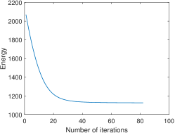
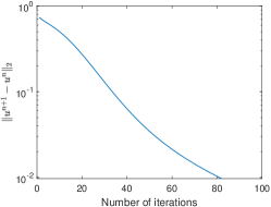
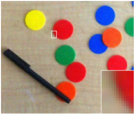
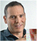
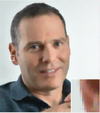
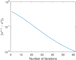
We use the proposed model to denoise images with Gaussian noise. We add Gaussian noise with SD=0.03SD=0.03 to three images: (a) portrait, (b) orange ball and (c) chips (shown in the first row of Figure 1). The noisy images and denoised images with α=0.01,η=0.5\alpha=0.01,\eta=0.5 are shown in the second and third rows of Figure 1, respectively. β=0.01\beta=0.01 is used for the orange ball, and β=0.005\beta=0.005 is used for the portrait and chips. For all of three examples, while they are denoised, sharp edges are kept. To demonstrate the efficiency of the proposed method, in Figure 2, we present the evolution of the energy and un+1un2\|u^{n+1}-u^{n}\|_{2} of the three examples shown in Figure 1. For the three examples, the energy decreases very fast and achieves the minimum within 40 iterations. Linear convergence is observed on the evolution of un+1un2\|u^{n+1}-u^{n}\|_{2}.

We next add Gaussian noise with SD=0.06SD=0.06 to these images. The noisy and denoised images are shown in Figure 3. The evolution of the energy w.r.t. the number of iterations are also shown in the third row. Our method is efficient and performs well. The energy achieves its minimum within 70 iterations. To better demonstrate the smoothing effect, we select the zoomed region of the orange ball and show the surface plot of each channel (RGB channel correspond the red, green and blue surface) in Figure 4. The surface plot of the noisy image is shown in the first row, which is very oscillating. The surface plot of the denoised image is shown in the second row. The surfaces of all three channels are very smooth which verifies the smoothing property of the proposed model.

We then compare the proposed model with the Polyakov action model [23], the color total variation (CTV) model [5] and the vectorial total variation (VTV) model [20]. For Gaussian noise with SD=0.06SD=0.06, the denoised images by these models are shown in Figure 5. In the proposed model, α=0.01,η=1,β=0.005\alpha=0.01,\eta=1,\beta=0.005 is used. In CTV and VTV, we set λ=6\lambda=6 and λ=0.1\lambda=0.1 respectively. Compared to other models, the proposed model smoothens flat regions while keeping sharp edges and textures. To quantify the difference of the denoised images, we compute and compare the PSNR and the SSIM [41] value of each denoised image in Figure 5 and present these values in Table 2(a). The proposed model and VTV outperform the other two models in both values. For the image of Chips, the result by VTV smoothens out almost all textures of the background. In comparison, these textures are kept by our proposed model. The number of iterations and CPU time of different methods are reported in Table 2(b). Due to the complex structures of the color elastica model, the proposed method is slower than the other three methods.

To further demonstrate the effectiveness of the proposed model, we compare these models on images with heavy Gaussian noise. In Figure 6, the noisy images contaminated by Gaussian noise with SD=0.15SD=0.15 are shown in the first column. The results by the proposed method, the Polyakov action, CTV and VTV are shown in Column 2 - Column 5, respectively. In the proposed model, α=0.01,η=1,β=0.02\alpha=0.01,\eta=1,\beta=0.02 is used. In CTV and VTV, we set λ=3\lambda=3 and λ=0.2\lambda=0.2 respectively. The PSNR and the SSIM value of each denoised image are shown in Table 2(a). The proposed model and VTV outperform the other two models in both values. While VTV is powerful in smoothing the flat region of images, the edges in the denoised image are oscillating. Compared to VTV, the proposed model provides results with smooth and sharp edges, and with larger PSNR values. This justifies the effectiveness of the high-order derivatives in the proposed model. The number of iterations and CPU time of different methods are reported in Talbe 2(b).

(a) (b) (c)
Refer to caption Refer to caption Refer to caption
Figure 7: (Possion noise with P=500P=500. α=0.01,η=0.3,β=0.005\alpha=0.01,\eta=0.3,\beta=0.005.) Image denoising by the proposed method on (a) the lighthouse, (b) the stop sign and (c) vegetables . The first row shows clean images. The second row shows noisy images. The third row shows denoised images.
(a) (b) (c)
Refer to caption Refer to caption Refer to caption
Figure 8: (Possion noise with P=500P=500. α=0.01,η=0.3,β=0.005\alpha=0.01,\eta=0.3,\beta=0.005.) The evolution of (first row) the energy and (second row) un+1un2\|u^{n+1}-u^{n}\|_{2} w.r.t. the number of iterations for results in Figure 7. (a) the lighthouse. (b) the stop sign and (c) vegetables.
(a) (b) (c)
Refer to caption Refer to caption Refer to caption
Figure 9: (Possion noise with P=100P=100. α=0.01,η=1,β=0.005\alpha=0.01,\eta=1,\beta=0.005.) Image denoising by the proposed method on (a) the lighthouse, (b) the stop sign and (c) vegetables. The first row shows noisy images. The second row shows denoised images.
(a) (b) (c)
Refer to caption Refer to caption Refer to caption
Figure 10: (Possion noise with P=100P=100. α=0.01,η=1,β=0.005\alpha=0.01,\eta=1,\beta=0.005.) The evolution of the energy w.r.t. the number of iterations for results in Figure 9. (a) the lighthouse, (b) the stop sign and (c) vegetables.
Refer to caption Refer to caption
Figure 11: (Poisson noise with P=100P=100. Smoothing effect.) Left: zoomed region of the (first row) noisy and (second row) denoised stop sign in Figure 9. Right: the surface plot of the left images. The RGB channels correspond to the red, green and blue surface, respectively.

(a)
Proposed Polyakov CTV VTV Stop Sign 32.05 (0.99) 28.52 (0.98) 30.36 (0.98) 31.73 (0.97) Vegetables 31.25 (0.98) 30.04 (0.98) 30.60 (0.97) 31.04 (0.98)
(b)
Proposed Polyakov CTV VTV Stop Sign 152 (52.47) 73 (2.03) 103 (2.05) 307 (7.94) Vegetables 128 (18.86) 85 (0.94) 111 (0.67) 243 (2.79)

Table 3: (Poisson noise with P=100P=100. Comparison of different methods.) (a) The PSNR (SSIM) value of the denoised images; (b) The number of iterations (CPU time in seconds) of different methods.

6.2 Image denoising for Poisson noise

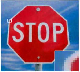
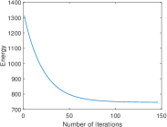
We explore the performance of the proposed method to denoise Poisson noise with P=500P=500. Our examples are (a) the lighthouse, (b) stop sign and (c) vegetables, see the first row in Figure 7. The noisy images and denoised images with α=0.01,η=0.3,β=0.005\alpha=0.01,\eta=0.3,\beta=0.005 are shown as the second row and third row in Figure 7, respectively. Similar to the performance on Gaussian noise, our method keeps sharp edges. The evolution of the energy and un+1un2\|u^{n+1}-u^{n}\|_{2} of these examples are shown in Figure 8. All energies achieve their minimum within 50 iteration.

Then, we add heavy Poisson noise with P=100P=100. The noisy and denoised images are shown in Figure 9. In this set of experiments, α=0.01,η=1,β=0.005\alpha=0.01,\eta=1,\beta=0.005 is used. We also show the evolution of energy against the number of iterations in Figure 10. All energies achieve their minimum in about 100 iterations. Figure 11 shows the surface plot of the zoomed region of the stop sign in Figure 9. The surface plot of the denoised image is smooth while that of the noisy image is very oscillating. We then compare the denoised images by the proposed model, the Polyakov action model, CTV and VTV in Table 3, which presents the PSNR, SSIM, number of iterations and CPU time of each denoised image. In the proposed model, α=0.01,η=1,β=0.005\alpha=0.01,\eta=1,\beta=0.005 is used. In CTV and VTV, we set λ=6\lambda=6 and λ=0.1\lambda=0.1 respectively. Among all methods, the proposed method provides results with the largest PSNR and SSIM value.

(a) (b) (c)
Refer to caption Refer to caption Refer to caption
Figure 12: (Effect of α\alpha.): (a) The orange ball. (b) The crystal cube. (c) Fruits.
(a) (b) (c)
Refer to caption Refer to caption Refer to caption
Figure 13: (Effect of α\alpha, Gaussian noise.) With α=101,102,103,104\alpha=10^{-1},10^{-2},10^{-3},10^{-4} and 10510^{-5}, plot of (first row) the surface area and (second row) the color elastica computed from noisy images w.r.t. SDSD. (a)-(c) corresponds to the orange ball, the crystal cube and fruits shown in Figure 12, respectively. Images have higher quality with smaller SDSD.
(a) (b) (c)
Refer to caption Refer to caption Refer to caption
Figure 14: (Effect of α\alpha, Poisson noise.) With α=101,102,103,104\alpha=10^{-1},10^{-2},10^{-3},10^{-4} and 10510^{-5}, plot of (first row) the surface area and (second row) the color elastica computed from noisy images against PP. (a)-(c) corresponds to the orange ball, the crystal cube and fruits shown in Figure 12, respectively. Images have higher quality with larger PP.
(a) (b) (c)
Refer to caption Refer to caption Refer to caption
(d) (e) (f)
Refer to caption Refer to caption Refer to caption
Figure 15: (Effect of α\alpha with β=0\beta=0.) The image is corrupted by Poisson noise with P=100P=100. (a) is the noisy image. (b)-(f) show denoised images with (b) α=101,η=2\alpha=10^{-1},\eta=2, (c) α=102,η=2\alpha=10^{-2},\eta=2, (d) α=103,η=4\alpha=10^{-3},\eta=4, (e) α=104,η=8\alpha=10^{-4},\eta=8 and (f) α=105,η=10\alpha=10^{-5},\eta=10.

6.3 Effect of α\alpha

The regularization term (first term) in (8) depends on two quantities: the surface area g\sqrt{g} and the color elastica k=13|Δguk|2\sum_{k=1}^{3}|\Delta_{g}u_{k}|^{2}. Both terms are closely dependent on α\alpha. In this section, we explore the effect of α\alpha by checking the behavior of both terms w.r.t. the noise level with α=101,102,103,104\alpha=10^{-1},10^{-2},10^{-3},10^{-4} and 10510^{-5}. The images used are shown in Figure 12: (a) orange ball, (b) crystal cube and (c) fruits.

The first experiment involves Gaussian noise for which the noise level is controlled by SDSD: images have better quality with smaller SDSD. In Figure 13, we show the behavior of both terms w.r.t. SDSD. The first row shows the surface area and the second row shows the color elastica. Both terms have larger values on images with heavier noise (larger SDSD) for most choices of α\alpha, which justifies the effectiveness of the proposed model (8). In Figure 13, as SD gets larger, the surface area increases faster with smaller α\alpha while the color elastica increases faster with larger α\alpha. To make both terms effective, α\alpha should not be too large or too small.

We then repeat these experiments on Poisson noise in which the noise level is controlled by PP, the number of photons. Images have better quality with larger PP. The behavior of the surface area and energy w.r.t. PP with different α\alpha is shown in Figure 14. Similar to the behavior for Gaussian noise, both terms have larger values with heavier noise (smaller PP). As α\alpha gets larger, the surface area has larger slope while the color elastica has smaller slope, which again implies that α\alpha should not be too large or too small to make both terms effective.

The above observation shows that the surface area is more effective with smaller α\alpha. However, even if our model only contains the surface area term (i.e., β=0\beta=0), we face the smoothness problem of edges if α\alpha is too small. In Figure 15, we use the proposed model with β=0\beta=0 and various α\alpha to denoise the orange ball which is contaminated by Poisson noise with P=100P=100. The noisy image, denoised image with α=101,102,103,104\alpha=10^{-1},10^{-2},10^{-3},10^{-4} and 10510^{-5} are shown in (a)-(f), respectively. Since the scale of surface area changes as α\alpha varies, we need to set different η\eta for each α\alpha. In our experiments, η=2,2,4,8,10\eta=2,2,4,8,10 are used as α\alpha varies from 10110^{-1} to 10510^{-5}. As α\alpha decreases, the edge of the orange ball in the denoised image becomes more oscillating. The cause of this observation may come from the model itself or the numerical algorithm, and is to be studied in the future.

6.4 Effect of β\beta

We fix α=102,η=0.01\alpha=10^{-2},\eta=0.01 and explore the effect of β\beta on our model. We use the image of crystal cube (shown in Figure 16(a)) with Gaussian noise with SD=0.06SD=0.06. We test our model with β=0,0.005,0.1\beta=0,0.005,0.1 and 0.20.2. The noisy and denoised images are shown in Figure 16. When β=0\beta=0, model (8) reduces to the Polyakov action model and there are perturbations in the flat region of the denoised image, see Figure 16(c). As β\beta gets larger, the flat part of the denoised image becomes smoother while the edges are kept. Similar to the elastica model for gray-scale images, the color elastica term helps smoothing the flat region. In Figure 17 we compare the surface plot of the zoomed region of the denoised image with β=0\beta=0 and β=0.005\beta=0.005. The rendered surface of the result with β=0.005\beta=0.005 is indeed much smoother. The evolution of the energy are shown in the third row of Figure 16. The color elastica term helps the energy to achieve the minimum faster. With non-zero β\beta, the energy of all experiments achieve the minimum within 80 iterations, while with β=0\beta=0, it takes nearly 150 iterations for the energy to achieve its minimum.

(a) (b)
Refer to caption Refer to caption
(c) (d) (e) (f)
Refer to caption Refer to caption Refer to caption Refer to caption
Figure 16: (Effect of β\beta, α=0.01,η=1\alpha=0.01,\eta=1.) The image is corrupted by Gaussian noise with SD=0.06SD=0.06. (a) is the clean image. (b) is the noisy image. (c)-(f) show denoised images and the evolution of the energy with (c) β=0\beta=0, (d) β=0.005\beta=0.005, (e) β=0.01\beta=0.01, (f) β=0.02\beta=0.02.
Refer to caption Refer to caption
Figure 17: (Effect of β\beta, surface plot.) Comparison of the surface plot of results in Figure 16 (c) and (d). Left: zoomed region of the denoised image in Figure 16 with (first row) β=0\beta=0 and (second row) β=0.005\beta=0.005. Right: the surface plot of the left images. The RGB channels correspond to the red, green and blue surface, respectively.
(a) (b) (c)
Refer to caption Refer to caption Refer to caption
Figure 18: (Image deblurring with α=0.001,η=0.05,β=5×10⁴\alpha=0.001,\eta=0.05,\beta=5\times 10^{-4}.) Clean images are first blurred by motion kernel and then contaminated by noise. Image deblurred by the proposed method on (a) the portrait, (b) chips and (c) vegetables. The first row shows blurred images. The second row shows deblurred images.

6.5 An example on image deblurring

To conclude this section, We test the proposed model on image deblurring by minimizing (47). The clean images are blurred by motion kernel and then contaminated by noise. In our algorithm, α=0.001,η=0.05,β=5×10⁴\alpha=0.001,\eta=0.05,\beta=5\times 10^{-4} is used. The clean images, blurred images and deblurred images are shown in Figure 18. The proposed model preserves color well.

7 Conclusion

We proposed a color elastica model (8), which incorporates the Polyakov action and the squared magnitude of mean curvature of the image treated as a two dimensional manifold in spatial-color space, to regularize color images. The proposed model is a geometric extension of the elastica model (2): when applied to gray-scale images, it reduces to a variant of the Euler elastica model. We also proposed an operator-splitting method to solve (8). The proposed method is efficient and robust with respect to parameter choices. The effectiveness of the proposed model and the efficiency of the numerical method are demonstrated by several experiments in color image regularization. The mean curvature term helps to better smooth noisy almost uniform (yet with some color changes) regions in images while keeping the edges sharp.

Acknowledgment

The authors would like to thank the anonymous reviewers of this article for helpful comments and suggestions.

References

  • [1] E. Bae, J. Shi, and X.-C. Tai, Graph cuts for curvature based image denoising, IEEE Transactions on Image Processing, 20 (2010), pp. 1199–1210.
  • [2] E. Bae, X.-C. Tai, and W. Zhu, Augmented Lagrangian method for an Euler’s elastica based segmentation model that promotes convex contours, Inverse Problems & Imaging, 11 (2017), pp. 1–23.
  • [3] L. Bar, A. Brook, N. Sochen, and N. Kiryati, Deblurring of color images corrupted by impulsive noise, IEEE Transactions on Image Processing, 16 (2007), pp. 1101–1111.
  • [4] T. Batard and M. Bertalmío, On covariant derivatives and their applications to image regularization, SIAM Journal on Imaging Sciences, 7 (2014), pp. 2393–2422.
  • [5] P. Blomgren and T. F. Chan, Color TV: total variation methods for restoration of vector-valued images, IEEE Transactions on Image Processing, 7 (1998), pp. 304–309.
  • [6] X. Bresson, P. Vandergheynst, and J.-P. Thiran, Multiscale active contours, International Journal of Computer Vision, 70 (2006), pp. 197–211.
  • [7] A. J. Chorin, T. J. Hughes, M. F. McCracken, and J. E. Marsden, Product formulas and numerical algorithms, Communications on Pure and Applied Mathematics, 31 (1978), pp. 205–256.
  • [8] K. Dabov, A. Foi, V. Katkovnik, and K. Egiazarian, Image denoising by sparse 3-D transform-domain collaborative filtering, IEEE Transactions on Image Processing, 16 (2007), pp. 2080–2095.
  • [9] L.-J. Deng, R. Glowinski, and X.-C. Tai, A new operator splitting method for the Euler elastica model for image smoothing, SIAM Journal on Imaging Sciences, 12 (2019), pp. 1190–1230.
  • [10] S. Di Zenzo, A note on the gradient of a multi-image, Computer Vision, Graphics, and Image Processing, 33 (1986), pp. 116–125.
  • [11] Y. Duan, W. Huang, J. Zhou, H. Chang, and T. Zeng, A two-stage image segmentation method using Euler’s elastica regularized Mumford-Shah model, in 2014 22nd International Conference on Pattern Recognition, IEEE, 2014, pp. 118–123.
  • [12] Y. Duan, Y. Wang, X.-C. Tai, and J. Hahn, A fast augmented lagrangian method for Euler’s elastica model, in International Conference on Scale Space and Variational Methods in Computer Vision, Springer, 2011, pp. 144–156.
  • [13] S. Esedoḡlu and R. March, Segmentation with depth but without detecting junctions, Journal of Mathematical Imaging and Vision, 18 (2003), pp. 7–15.
  • [14] R. Glowinski, Finite element methods for incompressible viscous flow, Handbook of Numerical Analysis, 9 (2003), pp. 3–1176.
  • [15] R. Glowinski, S. Leung, H. Liu, and J. Qian, On the numerical solution of nonlinear eigenvalue problems for the Monge-Ampère operator, ESAIM: Control, Optimisation and Calculus of Variations, 26 (2020), p. 118.
  • [16] R. Glowinski, H. Liu, S. Leung, and J. Qian, A finite element/operator-splitting method for the numerical solution of the two dimensional elliptic Monge–Ampère equation, Journal of Scientific Computing, 79 (2019), pp. 1–47.
  • [17] R. Glowinski, S. Luo, and X.-C. Tai, Fast operator-splitting algorithms for variational imaging models: Some recent developments, in Handbook of Numerical Analysis, vol. 20, Elsevier, 2019, pp. 191–232.
  • [18] R. Glowinski, S. J. Osher, and W. Yin, Splitting methods in communication, imaging, science, and engineering, Springer, 2017.
  • [19] R. Glowinski, T.-W. Pan, and X.-C. Tai, Some facts about operator-splitting and alternating direction methods, Splitting Methods in Communication, Imaging, Science, and Engineering, (2017), pp. 19–94.
  • [20] B. Goldluecke, E. Strekalovskiy, and D. Cremers, The natural vectorial total variation which arises from geometric measure theory, SIAM Journal on Imaging Sciences, 5 (2012), pp. 537–563.
  • [21] V. Grimm, R. I. McLachlan, D. I. McLaren, G. Quispel, and C. Schönlieb, Discrete gradient methods for solving variational image regularisation models, Journal of Physics A: Mathematical and Theoretical, 50 (2017), p. 295201.
  • [22] Y. He, S. H. Kang, and H. Liu, Curvature regularized surface reconstruction from point cloud, arXiv preprint arXiv:2001.07884, (2020).
  • [23] R. Kimmel, N. Sochen, and R. Malladi, From high energy physics to low level vision, in International Conference on Scale-Space Theories in Computer Vision, Springer, 1997, pp. 236–247.
  • [24] E. Kobler, A. Effland, K. Kunisch, and T. Pock, Total deep variation: A stable regularizer for inverse problems, arXiv preprint arXiv:2006.08789, (2020).
  • [25] S. Lefkimmiatis, Non-local color image denoising with convolutional neural networks, in Proceedings of the IEEE Conference on Computer Vision and Pattern Recognition, 2017, pp. 3587–3596.
  • [26] H. Liu, R. Glowinski, S. Leung, and J. Qian, A finite element/operator-splitting method for the numerical solution of the three dimensional Monge–Ampère equation, Journal of Scientific Computing, 81 (2019), pp. 2271–2302.
  • [27] M. Nitzberg, D. Mumford, and T. Shiota, Filtering, Segmentation and Depth, vol. 662, Springer, 1993.
  • [28] A. M. Polyakov, Quantum geometry of bosonic strings, in Supergravities in Diverse Dimensions: Commentary and Reprints (In 2 Volumes), World Scientific, 1989, pp. 1197–1200.
  • [29] G. Rosman, L. Dascal, A. Sidi, and R. Kimmel, Efficient Beltrami image filtering via vector extrapolation methods, SIAM Journal on Imaging Sciences, 2 (2009), pp. 858–878.
  • [30] G. Rosman, L. Dascal, X.-C. Tai, and R. Kimmel, On semi-implicit splitting schemes for the Beltrami color image filtering, Journal of Mathematical Imaging and Vision, 40 (2011), pp. 199–213.
  • [31] G. Rosman, X.-C. Tai, L. Dascal, and R. Kimmel, Polyakov action minimization for efficient color image processing, in European Conference on Computer Vision, Springer, 2010, pp. 50–61.
  • [32] A. Roussos and P. Maragos, Tensor-based image diffusions derived from generalizations of the total variation and beltrami functionals, in 2010 IEEE International Conference on Image Processing, IEEE, 2010, pp. 4141–4144.
  • [33] G. Sapiro, Vector-valued active contours, in Proceedings CVPR IEEE Computer Society Conference on Computer Vision and Pattern Recognition, IEEE, 1996, pp. 680–685.
  • [34] G. Sapiro and D. L. Ringach, Anisotropic diffusion of multivalued images with applications to color filtering, IEEE Transactions on Image Processing, 5 (1996), pp. 1582–1586.
  • [35] J. Shen, S. H. Kang, and T. F. Chan, Euler’s elastica and curvature-based inpainting, SIAM journal on Applied Mathematics, 63 (2003), pp. 564–592.
  • [36] N. Sochen, R. Kimmel, and R. Malladi, A general framework for low level vision, IEEE Transactions on Image Processing, 7 (1998), pp. 310–318.
  • [37] A. Spira, R. Kimmel, and N. Sochen, A short-time Beltrami kernel for smoothing images and manifolds, IEEE Transactions on Image Processing, 16 (2007), pp. 1628–1636.
  • [38] X.-C. Tai, J. Hahn, and G. J. Chung, A fast algorithm for Euler’s elastica model using augmented Lagrangian method, SIAM Journal on Imaging Sciences, 4 (2011), pp. 313–344.
  • [39] L. Tan, W. Liu, and Z. Pan, Color image restoration and inpainting via multi-channel total curvature, Applied Mathematical Modelling, 61 (2018), pp. 280–299.
  • [40] D. Tschumperle and R. Deriche, Vector-valued image regularization with PDEs: A common framework for different applications, IEEE Transactions on Pattern Analysis and Machine Intelligence, 27 (2005), pp. 506–517.
  • [41] Z. Wang, A. C. Bovik, H. R. Sheikh, and E. P. Simoncelli, Image quality assessment: from error visibility to structural similarity, IEEE transactions on image processing, 13 (2004), pp. 600–612.
  • [42] Z. Wang, J. Zhu, F. Yan, and M. Xie, Fidelity-Beltrami-sparsity model for inverse problems in multichannel image processing, SIAM Journal on Imaging Sciences, 6 (2013), pp. 2685–2713.
  • [43] A. Wetzler and R. Kimmel, Efficient beltrami flow in patch-space, in International Conference on Scale Space and Variational Methods in Computer Vision, Springer, 2011, pp. 134–143.
  • [44] D. Yang and J. Sun, BM3D-Net: A convolutional neural network for transform-domain collaborative filtering, IEEE Signal Processing Letters, 25 (2017), pp. 55–59.
  • [45] M. Yashtini and S. H. Kang, A fast relaxed normal two split method and an effective weighted TV approach for Euler’s elastica image inpainting, SIAM Journal on Imaging Sciences, 9 (2016), pp. 1552–1581.
  • [46] J. Zhang and K. Chen, A new augmented Lagrangian primal dual algorithm for elastica regularization, Journal of Algorithms & Computational Technology, 10 (2016), pp. 325–338.
  • [47] J. Zhang, R. Chen, C. Deng, and S. Wang, Fast linearized augmented Lagrangian method for Euler’s elastica model, Numerical Mathematics: Theory, Methods and Applications, 10 (2017), pp. 98–115.
  • [48] W. Zhu, T. Chan, and S. Esedoḡlu, Segmentation with depth: A level set approach, SIAM Journal on Scientific Computing, 28 (2006), pp. 1957–1973.
  • [49] W. Zhu, X.-C. Tai, and T. Chan, Image segmentation using Euler’s elastica as the regularization, Journal of Scientific Computing, 57 (2013), pp. 414–438.
  • [50] D. Zosso and A. Bustin, A primal-dual projected gradient algorithm for efficient Beltrami regularization, Computer Vision and Image Understanding, (2014), pp. 14–52.